Aortic Abnormalities
Computed tomography (CT) is commonly used to diagnose abnormalities of the aorta or its branches when they are suspected clinically or because of radiographic abnormalities.
Congenital Anomalies
Congenital abnormalities of the aorta and its branches are readily diagnosed with CT, and no other study is usually needed unless the anomaly is complex or is associated with congenital heart disease.
Aberrant Right Subclavian Artery
Aberrant right subclavian artery is a relatively common anomaly (1 in 100 patients). It does not usually produce a recognizable abnormality on chest radiographs and is usually detected incidentally on CT.
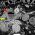
In patients with this anomaly the aortic arch is often higher than normal. The aberrant right subclavian artery arises from the medial wall of the descending aorta, as its last branch ( Fig. 3.1 ), passes to the right, behind the esophagus, and ascends on the right toward the thoracic inlet. It lies more posteriorly than is normal for the subclavian artery, often anterolateral to the spine. At its point of origin the artery may be dilated, or, thinking of it in a more complicated way, the artery may arise from an aortic diverticulum (termed diverticulum of Kommerell ). This may cause compression of the esophagus and symptoms of dysphagia. In some patients the diverticulum or the anomalous artery becomes aneurysmal ( Fig. 3.2 ).


Right Aortic Arch
There are two primary types of right aortic arch: right arch associated with aberrant left subclavian artery and mirror-image right arch . Right arch with an aberrant left subclavian artery is most common and is present in about 1 in 1000 people. It is the reverse of a left arch with an aberrant right subclavian artery ( Fig. 3.3 ). However, an associated aortic diverticulum is more common in the presence of a right arch. With this anomaly, there is a low frequency (5%–10%) of associated congenital heart lesions, usually simple anomalies, such as an atrial septal defect. Mirror-image right arch is relatively uncommon and is almost always (98%) associated with congenital heart disease (usually complex anomalies such as tetralogy of Fallot). The CT appearance of a mirror-image arch is well described by its name; it is the mirror image of a normal left arch, with a left innominate artery present. With both types of right arch the descending aorta is usually left-sided, crossing from right to left in the lower mediastinum.

Double Aortic Arch
Double aortic arch is relatively uncommon, but because a plain radiograph shows a mediastinal abnormality (representing the right arch), it is often evaluated with CT. This anomaly is uncommonly associated with congenital heart disease, but because a complete vascular ring is present, symptoms of dysphagia are common. In this anomaly the ascending aorta splits into right and left arches. The right arch, which is usually higher and larger than the left, passes to the right of the trachea and esophagus, crosses behind these structures, and rejoins the left arch, which occupies a relatively normal position ( Fig. 3.4 ). Each arch is smaller than normal and smaller than the descending aorta. Each arch also gives rise to a subclavian artery and a carotid artery, and no innominate artery is present. This results in a symmetric appearance of the great vessels in the supra-aortic mediastinum that is highly suggestive of the diagnosis.

Aortic Coarctation and Pseudocoarctation
Coarctation, and its rare variant pseudocoarctation, can be readily diagnosed with CT, but catheterization is usually necessary to measure intra-arterial pressures and thus the significance of the vascular obstruction.
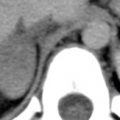
The site of narrowing in coarctation is generally at the aortic isthmus, distal to the origin of the left subclavian artery and near the ligamentum arteriosum ( juxtaductal coarctation ). On CT the narrowed segment is often visible because it is decidedly smaller than the aorta above and below this level ( Fig. 3.5 ). This size difference reflects not only the narrowed segment at the coarctation but also some dilatation of the prestenotic and poststenotic aorta. A lengthy narrowing of the aortic arch (hypoplasia) is less common.

Images reconstructed in the plane of the aortic arch can show coarctation to best advantage. One word of caution: the degree of narrowing at the site of coarctation may be overestimated if the reformatted plane is slightly off the sagittal plane of the aorta. Dilatation of internal mammary arteries or intercostal arteries (usually the third through eighth) acting as collateral pathways can be seen.
In pseudocoarctation the aortic arch is kinked anteriorly and its lumen is somewhat narrowed, but a significant pressure gradient across the kink and collateral vessels are not present. The aortic arch is higher than normal and initially descends in an abnormally anterior position, well in front of the spine. At a level near the carina, however, the aorta again angles posteriorly, forming a second arch, and assumes its normal position anterolateral to the spine. This anomaly is usually not associated with symptoms.
Both coarctation and pseudocoarctation are associated with congenital bicuspid aortic valve (30%–85% of patients with coarctation); this may result in aortic stenosis. In some patients, CT shows aortic valve calcification, allowing this diagnosis to be suggested.
Aortic Aneurysm
If the ascending aorta measures more than 4 cm in diameter, it is usually referred to as dilated or ectatic . Although a diagnosis of “aortic dilatation” as opposed to “aortic aneurysm” is somewhat arbitrary, this chapter uses aortic dilatation or ectasia to refer to a generalized dilatation of relatively mild degree (4 cm), with the implication that it is not necessarily a serious problem. Aneurysm , in contrast, refers to a more focal abnormality or more severe dilatation of the entire aorta (≥5 cm). At the risk of oversimplification, for the ascending aorta, a diameter of 4 cm corresponds to aortic dilatation, 5 cm corresponds to aortic aneurysm, and 6 cm corresponds to increased risk of rupture. Surgery or insertion of an endovascular stent graft is generally recommended with an aortic diameter of 5.5 cm.
With atherosclerotic aneurysms the aortic wall is often thickened and calcified. On unenhanced CT the diagnosis can sometimes be made because of visible peripheral calcification, and thrombus within the aneurysm or adjacent hematoma may appear higher in attenuation than aortic blood.
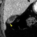
With contrast medium infusion, the lumen of the aorta, the diameter of the aneurysm, and the thickness of the aortic wall can be defined ( Fig. 3.6 ). There may be visible areas of plaque or thrombus within the lumen of the aneurysm ( Fig. 3.7 ); these may also be calcified. Plaque often appears low in attenuation relative to the aortic wall because of its fat content, or because of some opacification of the aortic wall itself. Plaque can also be seen in patients with atherosclerosis who do not have aortic dilatation. Focal ulceration of a plaque or thrombus ( Fig. 3.7 ) may occur and should be distinguished from a penetrating atherosclerotic ulcer (PAU), if possible (see later discussion).


Aneurysms are often described as fusiform or saccular, depending on their appearance. The differential diagnosis of an aneurysm varies with its location. An ascending aortic aneurysm may occur with atherosclerosis, Marfan syndrome, cystic medial necrosis, syphilis, or aortic valvular disease. An aneurysm near the ligamentum arteriosum may be atherosclerotic in origin, a ductus aneurysm (aneurysm at the site of the ductus arteriosus or a ductus diverticulum), mycotic, related to coarctation, or posttraumatic (i.e., a pseudoaneurysm). Mycotic aneurysms are usually focal, and they may be associated with periaortic inflammation (visible as edema of periaortic fat) or abscess (with localized fluid collections); gas bubbles may be seen within soft tissues. A descending aortic aneurysm is usually atherosclerotic.
Aortic Trauma
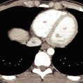
Spiral CT has assumed an important role in the diagnosis of aortic injuries, usually associated with a fall or automobile accident. Traumatic aortic laceration, rupture, or pseudoaneurysm occurs most commonly in the following areas: (1) at the aortic root, (2) at the level of the ligamentum arteriosum, or (3) at the diaphragm and aortic hiatus. Patients with aortic root injury often die at the scene of injury; in patients who reach the hospital, injuries at the level of the ligamentum are most common ( Fig. 3.8 ).

Mediastinal hematoma (fluid with an attenuation of about 50 Hounsfield units [HU]) contiguous with the aorta is invariably visible on CT in patients with aortic laceration or rupture ( Fig. 3.8 ); the absence of hematoma effectively excludes this diagnosis. The presence of hematoma at the location of a sternal or vertebral fracture does not predict aortic injury.
Contrast-enhanced multidetector CT (MDCT) with thin slices (e.g., 1.25 mm) is highly accurate in diagnosing acute aortic laceration or rupture, with a sensitivity of nearly 100%. The site of rupture or tear may have the appearance of an aortic wall irregularity, dissection, or focal aneurysm ( Fig. 3.8 ); extravasation of contrast medium is rarely seen, and if present requires immediate attention. It has been suggested that aortography is not needed if a mediastinal hematoma is not visible, or there is no recognizable aortic abnormality in patients with a mediastinal hematoma. Aortography may be necessary in some patients with inadequate CT studies or questionable CT findings, or may be performed at the time a stent graft is placed for treatment.
Chronic posttraumatic pseudoaneurysm is usually located in the region of the aortopulmonary window, below the takeoff of the left subclavian artery and near the ligamentum arteriosum ( Fig. 3.9 ). Calcification of the wall of the pseudoaneurysm may be present.

Acute Aortic Syndromes
Acute aortic syndrome is a term used to describe several aortic abnormalities that present with acute chest pain and are often associated with similar predisposing conditions. These include aortic dissection , intramural hematoma (IMH), and penetrating atherosclerotic ulcer (PAU). They have in common the presence of penetration of the aortic intima or disruption of the media.
Aortic Dissection
Aortic dissection is often associated with hypertension, weakness of the aortic wall (e.g., Marfan syndrome or cystic medial necrosis), or trauma. Patients usually have acute chest pain. The goal in diagnosing dissection is the demonstration of an intimal flap, displaced inward from the edge of the aorta, separating the true and false channels. CT is ideally suited to this because of its cross-sectional format.
Two schemes for the classification of aortic dissections have been proposed by DeBakey and Daily. Daily’s classification, commonly known as the Stanford classification , is most frequently used because of its simplicity and relevance to treatment.
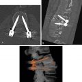
With use of the Stanford classification, aortic dissections are divided into types A and B. Type A dissections involve the ascending aorta ( Fig. 3.10 ); approximately two-thirds of acute dissections are type A. Because of the possibility of retrograde dissection and rupture into the pericardium (resulting in tamponade) or occlusion of the coronary or carotid arteries, these dissections are usually treated surgically with grafting or stent graft placement in the region of the tear. Electrocardiogram (ECG)-gated MDCT can provide exceptional detail in patients with a type A dissection ( Fig. 3.11 ). Type B dissections do not involve the aortic arch but typically arise distal to the left subclavian artery ( Fig. 3.12 ). These are generally treated medically (by normalization of blood pressure). Placement of an endovascular stent graft is also used for treatment of some type B dissections ( Fig. 3.20 ).


CT is highly sensitive and specific (>95%) in diagnosing dissection and in determining its location and type and the aortic branches involved; consequently it is an excellent diagnostic procedure in patients with a suggestive clinical presentation. Transesophageal echocardiography may be performed in some patients with suspected acute dissection; it is highly sensitive but has lower specificity (70%). The accuracy of magnetic resonance imaging is similar to that of CT, and magnetic resonance imaging may be performed in patients unable to have radiographic contrast agents; it may also be performed before surgery in patients shown to have a type A dissection. CT or magnetic resonance imaging can be used to follow up patients with dissection after treatment to watch for redissection or extension of the dissection.
In patients with suspected dissection, CT should be performed with rapid contrast medium infusion. With use of a spiral technique, it is easy to scan through the great vessels, aortic arch, and descending aorta (1.25- or 2.5-mm detector width for MDCT) during rapid contrast medium infusion (at 2.5–3.5 mL per second) and to continue the scans to the level of the aortic bifurcation in the abdomen. A scanning delay of approximately 20 to 30 seconds should be used after the start of injection, or scanning should be timed by the scanner to show aortic enhancement. Contrast-enhanced scans are usually preceded by unenhanced scans through the thorax to look for IMH (see later discussion).
In a patient with dissection the intimal flap is usually delineated by contrast medium filling both the true channel and the false channel. A fenestration in the aortic intima may be visible at the site of origin of the dissection ( Fig. 3.12 ). The true and false channels can often be distinguished on the basis of the following CT findings ( Figs. 3.10A, 3.11, and 3.12 ), although this may be difficult or impossible in some cases:
- •
If the aortic root or ascending aorta is normal in appearance, trace the opacified aortic lumen on adjacent slices to see which of the distal channels it communicates with. This represents the true channel.
- •
The false channel tends to be located lateral to the true channel at the level of the aortic arch and spirals posteriorly in the descending aorta. Because of this characteristic location, the left renal artery is the abdominal branch most likely to arise from the false channel.
- •
The true lumen is usually smaller.
- •
The false channel is usually more irregular in contour, and it may contain strands of tissue termed cobwebs within the contrast medium stream.
- •
The false channel is more likely to contain a thrombus.
- •
Blood flow is slower and opacification is often delayed in the false channel.
- •
Aortic wall calcification may be seen lateral to the true channel; it is usually displaced inward from the wall of the false channel.
The false channel may be opacified or thrombosed. Thrombosis of the false channel is associated with better prognosis. The false channel may dilate and sometimes ruptures. Overall, the aortic diameter may be increased at the site of a dissection because of dilatation of the false channel.
Artifacts, arising because of cardiac motion or vascular pulsations during the scan, may mimic an intimal flap. They are commonly seen at the level of the aortic root and in the descending aorta, adjacent to the border of the left side of the heart. Typically, they are less sharply defined than a true intimal flap, may extend beyond the edges of the aorta, or are inconsistently seen from one level to the next.
Two other abnormalities may closely mimic the clinical presentation of dissection. Consequently, these may be seen on CT scans obtained to evaluate possible dissection in patients with acute aortic syndrome. These are IMH and PAU. The appearances of dissection, IMH, and PAU may overlap, with features of each being seen in a single case.
Intramural Hematoma
IMH results from hemorrhage into the aortic wall. Acute IMH may closely mimic the presentation of dissection (acute chest pain in a patient with hypertension). It is thought to occur because of bleeding from the vasa vasorum, although in some cases it may represent a sealed-off dissection.
On contrast-enhanced scans, the IMH appears as a smooth and crescentic or, less commonly, concentric thickening of the aortic wall ( Figs. 3.13 and 3.14 ). On unenhanced scans the IMH appears denser than unenhanced blood in the aortic lumen; because of this characteristic appearance, CT in a patient with suspected dissection should be preceded by unenhanced scans through the thorax. If unenhanced scans are not obtained prospectively, delayed unenhanced scans may be obtained. Inward displacement of intimal calcification can also be seen on unenhanced scans.