FIGURE 6.1 Oblique MRI of the long head biceps tendon. Intermediate-weighted fat-suppressed MR image oriented along the course of the long head of the biceps profiles the proximal attachment to the glenoid and labrum as well as showing the intra- and extra-articular segments.
The normal MRI appearance of the long head of the biceps tendon is low signal intensity on all imaging sequences. As a result of the course of the biceps tendon, different sections of the tendon are optimally evaluated in coronal oblique, sagittal oblique, and axial imaging planes. Axial and coronal planes have been considered the best for evaluating the distal descending portion of the tendon and the tendon sheath as well as for assessing the biceps insertion at the superior labrum. Sagittal and coronal sections show the intra-articular segment. Some authors advocate the use of a biceps–tendon-defined coronal oblique imaging plane to facilitate the evaluation of the intra-articular biceps tendon, stating that this technique results in decreased partial-volume effects and allows better localization and characterization of biceps pathology (Fig. 6.1) (11).
Magic Angle Phenomenon
A short segment of the long bicipital tendon located proximal to the intertubercular groove lies 55 degrees to MR imagers with a vertical static magnetic field. Therefore, this region can exhibit higher signal intensity on short TE images related to structural anisotropy of the collagen, which is susceptible to the “magic angle” phenomenon (12). This elevated signal intensity can mimic a rotator cuff or biceps tendon lesion on short TE images; however, this signal should decrease in the normal tendon on longer TE images.
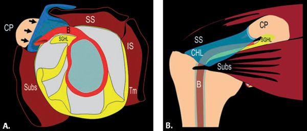
FIGURE 6.2 Diagrams of the rotator cuff interval. A: Sagittal diagram of the glenoid and capsule showing the RCI (arrows) defined as the space between the supraspinatus tendon (SS) and subscapularis tendon (Subs) that results from the interposition of the coracoid process (CP) between these two tendons. The anchor for the long head of the biceps tendon (B), the superior glenohumeral ligament (SGHL), and the rotator interval capsule (arrow) are depicted. B: Coronal diagram of the shoulder depicting the rotator interval capsule bordered superiorly by the supraspinatus tendon (SS) and inferiorly by the subscapularis tendon (Subs). It occurs as a result of the interposition of the coracoid process (CP) between these tendons. The long head of the biceps tendon (B) is also shown. The bursal-sided coracohumeral (CHL) and articular-sided superior glenohumeral ligament (SGHL) relationship is emphasized.
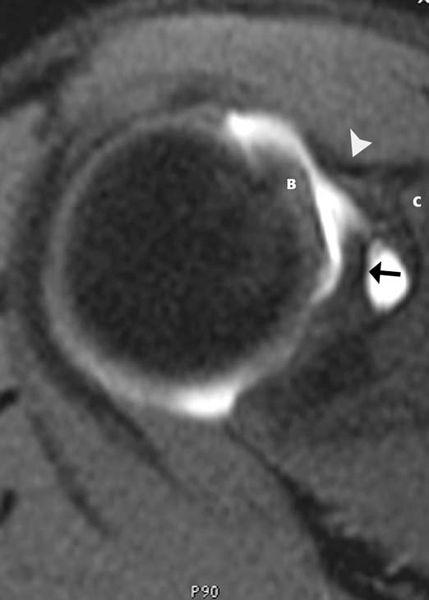
FIGURE 6.3 Proximal rotator cuff interval. Axial T1-weighted fat-suppressed MR image obtained after contrast injection into the joint shows the superior glenohumeral ligament (arrow) emanating from the superior glenoid, the coracohumeral ligament (arrowhead) arising from the coracoid process (C), and the biceps tendon (B).
Tenosynovitis
A large amount of fluid in the biceps tendon sheath without an associated increase in glenohumeral joint fluid is suggestive of biceps tenosynovitis (9, 13), but this accepted concept requires further study. In general, inflammatory changes in the synovial reflection of the biceps tendon are divided into two categories, those that occur in isolation and those that occur in the presence of rotator cuff pathology.
An abnormal amount of fluid in the tendon sheath, biceps tenosynovitis, is usually caused by degeneration or trauma, including impingement. It can also be related to synovitis from an inflammatory arthropathy such as rheumatoid arthritis. The Yergason test, which stresses the biceps tendon, aids in diagnosing this condition. Pain is produced in the biceps groove when the arm is placed in forced supination. This test does not stress the rotator cuff tendons, which allows for distinction from rotator cuff impingement.
MR studies usually demonstrate an abnormal amount of fluid in the tendon sheath (14, 15) (Fig. 6.7). The fluid should completely surround the tendon to comfortably make this diagnosis. The vessels in the intertubercular groove should not be mistaken for abnormal fluid (9). Occasionally, a stenosing tenosynovitis in the sheath with internal adhesions is seen. This is best detected with MR arthrography in which there is a lack of passage of contrast beyond a certain region of the tendon sheath.
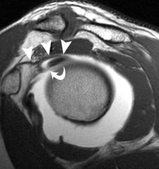
FIGURE 6.4 Rotator cuff interval and biceps pulley. Sagittal T1-weighted MR image obtained after contrast administration into the joint profiles the course of the coracohumeral ligament (arrowheads) and superior glenohumeral ligament (curved arrow) as they reinforce the biceps tendon at the junction of its intra- and extra-articular position. This region has been referred to as the biceps pulley and emphasizes the bursal-sided position of the coracohumeral ligament with respect to the articular-sided position of the superior glenohumeral ligament.
Biceps tenosynovitis can be treated conservatively or with aspiration and injection of medications such as anesthetizing agents and steroids. Tenodesis is performed when pain persists.
Tendinosis
Inflammation and degeneration of the tendon result in tendinosis. This is a condition that can be seen in all age groups. Patients report pain over the anterior aspect of the shoulder. It may be localized to the intertubercular groove or radiate caudal or cephalad to it. The pain is usually gradual in onset. The long head of the biceps tendon may be impinged when it courses in the region of the critical zone under the supraspinatus tendon. Although impingement syndromes are discussed in greater detail in Chapter 4, an imaging sign that could support biceps impingement or friction syndromes may include bone marrow edema about the intertubercular sulcus as well as changes within the tendon proper (Fig. 6.8). The latter may be manifested by tenosynovitis and tendinosis. Chronic tendinosis can lead to rupture of the tendon. A history of acute trauma or overuse of the shoulder is less common.
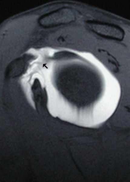
FIGURE 6.5 Rotator cuff interval tear. Sagittal T1-weighted fat-suppressed MR image after the administration of intra-articular contrast shows an abnormal rotator cuff interval capsule (arrow) with contrast extending to the undersurface of the coracoid consistent with the tear. Physical examination findings revealed a snapping sensation of the biceps with palpation.
Microscopically, the tendon may demonstrate increased vascularity, hypercellularity, and fibrosis. The severity of tendinosis is related to its duration and the age of the patient (16). Tendinosis can lead to adhesive capsulitis and tendon rupture.
The diagnosis of tendinosis, and its distinction from partial tears of the tendon is made through analysis of the signal intensity and morphology of the biceps tendon. Intrinsic high signal intensity within the tendon on T1-weighted MR images without brightening to the degree of simple fluid on T2-weighted MR images is characteristic of tendinosis (Fig. 6.9). With regard to morphology, the alteration encountered may parallel the chronicity of the process. In earlier stages of tendinosis, the tendon may have an enlarged appearance. When isolated to the intracapsular portion of the tendon and when severe in nature, this process has been termed the hourglass biceps tendon (Fig. 6.10). This hypertrophy of the intracapsular biceps tendon leads to its incarceration within the joint, inhibiting passive and active elevation and causing pain. In Boileau et al.’s (17) series of 21 patients, the mean diameter of the intracapsular biceps measured 12 mm 3 mm, whereas the component within the intertubercular sulcus measured 6 mm 2 mm. In the later stages of tendinosis, an attenuated appearance may predominate; the latter has been referred to as attritional tendinosis.
As previously discussed, the magic angle phenomenon may affect the biceps tendon as it goes from the intra-articular region into the bicipital groove, a region that lies approximately 55 degrees to the static magnetic field on short TE images. This appearance can simulate mild tendinosis. This is also a common location for impingement. Because this location is a frequent site of magic angle phenomenon and if there is a lack of increased signal intensity on T2-weighted MR images, the clinician may put the magic angle phenomenon as the top possibility when describing this appearance.
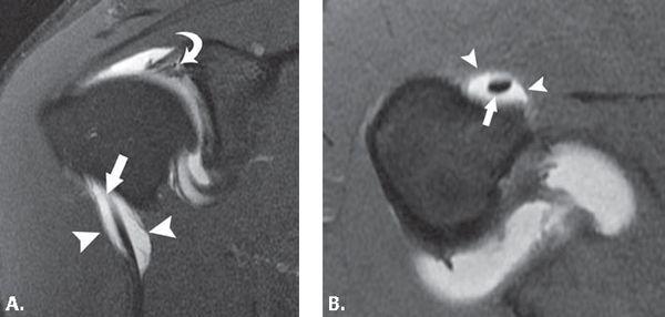
FIGURE 6.6 Biceps tendon synovial reflection. Coronal (A) and axial (B) T1-weighted fat-suppressed MR images through the shoulder after intra-articular contrast injection show normal distention of the synovial reflection (arrowheads) of the biceps tendon (arrow). The coronal (A) image shows intrasubstance superior labral tear (curved arrow) as evidenced by contrast extending into the labral substance.
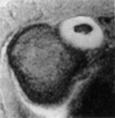
FIGURE 6.7 Biceps tenosynovitis. Axial gradient-echo T2*-weighted MR image of the shoulder demonstrates a large amount of fluid within the synovial reflection of the biceps tendon that is out of proportion to the fluid seen in the joint. This is consistent with the diagnosis of tenosynovitis.
Partial- and Full-thickness Tears
Partial tears of the long head of the biceps tendon were first described in 1934 by Gilcrest (18) and, along with a variety of other pathologic lesions affecting this structure, was included in the term “common bicipital syndrome.” Pathology of the proximal portion of the biceps tendon is often associated with subacromial impingement and rotator cuff tears, rendering the clinical presentation and physical examination findings nonspecific (19). Partial-thickness tears may present as thinning, irregularity, fragmentation, or increased signal intensity on MR images (Fig. 6.11). Longitudinal fissures and splits of the tendon are commonly encountered types of partial tears (Fig. 6.12). This is most common superiorly. A bifid biceps tendon can be mistaken for a longitudinal split of the biceps tendon. The distinction from a tear can be difficult but is more likely if the bifid tendon is seen on all axial MR images and extends into the glenohumeral joint toward the attachment on the supraglenoid tubercle. The labral attachment should also appear intact to distinguish from a superior labral anterior–posterior (SLAP) lesion associated with a longitudinal biceps tendon tear.
Most tears of the long head of the biceps tendon occur at the proximal portion of the bicipital groove, usually in patients older than age 40 years. Less commonly, complete failure occurs just proximal to the bicipital groove and rarely at the biceps labral junction. Musculotendinous ruptures are infrequent and are usually associated with significant trauma. In general, the region of failure occurs at a site of pre-existing tendinosis. Full-thickness ruptures have been reported in bodybuilders and weight lifters (20). As a result of the robust tensile strength of the normal biceps tendon, acute rupture of the healthy tendon is a rare occurrence and requires extreme circumstances.
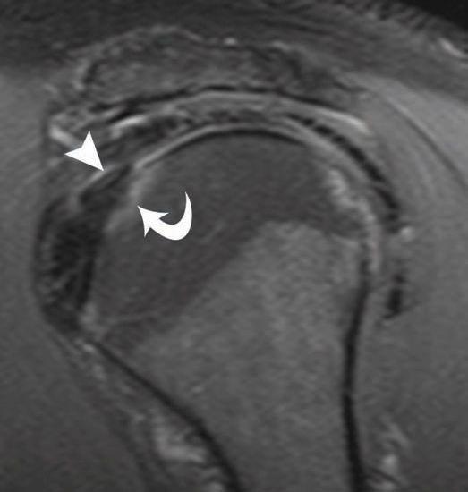
FIGURE 6.8 Biceps tendon impingement. Sagittal intermediate-weighted fat-suppressed MR image shows intrinsic intermediate signal within the biceps tendon (arrowhead) consistent with tendinosis as well as bone marrow edema (curved arrow) at the superior extent of the lesser tuberosity at the junction of the intra- and extra-articular biceps tendon. These imaging findings support the clinical diagnosis of biceps tendon impingement.
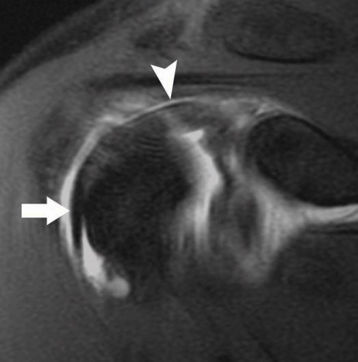
FIGURE 6.9 Biceps tendinosis. Coronal intermediate-weighted fat-suppressed MR image through the anterior aspect of the shoulder shows a caliber change in the biceps tendon with thickening of the intra-articular (arrowhead) portion versus normal-appearing morphology (arrow) in the intertubercular sulcus.
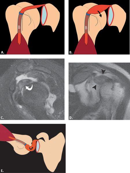
FIGURE 6.10 Hourglass biceps tendon. Diagram shows normal (A) and the hourglass biceps tendon (B). Sagittal T1-weighted fat-suppressed MR arthrogram image (C) profiles the massively enlarged biceps tendon (curved arrow). Coronal T1-weighted MR arthrogram image (D) through the anterior aspect of the shoulder emphasizes the mass-like enlargement of the intra-articular biceps (arrowheads). Diagram (E) shows the appearance of the hourglass biceps tendon in the abducted and externally rotated position.
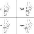
Neer (21) has stated that biceps tendon ruptures are extremely uncommon without coexisting rotator cuff abnormalities and has classified full-thickness tears of the long head of the biceps tendon into three types. Type 1 is a tear without retraction; type 2 is a tear with partial retraction; and type 3 is a self-attaching tear without retraction. This latter type of tear can be difficult to diagnose clinically and MRI can be of help in this situation. Some clinicians have found it difficult to distinguish fibrous tissue in the bicipital groove from the bicipital tendon itself. In the acute setting, however, patients often report hearing a “pop” and identifying a subsequent deformity of the arm resulting from the distal displacement of the torn extracapsular biceps tendon and contracted muscle. This appearance has been referred to as the “Popeye” sign.
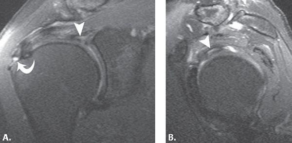
FIGURE 6.11 Partial tear of intra-articular biceps tendon. Coronal (A) and sagittal (B) intermediate-weighted fat-suppressed MR images through the shoulder show bright signal within the substance of the intra-articular biceps tendon (arrowhead) consistent with a partial tear. On the coronal (A) image, incidental note is made of a low-grade bursal-sided tear of the supraspinatus tendon (curved arrow) superimposed on a background of tendinosis.
MRI allows direct visualization of the biceps tendon rupture and is evidenced by tendon discontinuity. The identification of the location of the rupture and ultimate location of the torn ends of the tendon should be described. When there is distal retraction of the muscle, there is absence of the tendon in all or a portion of the bicipital groove. When the failure occurs at the proximal aspect of the intertubercular sulcus, the stump of the torn proximal biceps tendon can be difficult to identify and often displaces anteriorly into the region of the rotator cuff interval capsule (Fig. 6.13). In addition, a retained biceps tendon stump at the superior glenoid from a tear can cause glenoid and humeral head chondromalacia through a “windshield wiper” mechanism and it is important to remove it before this occurs (22).
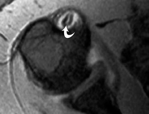
FIGURE 6.12 Partial tear of the intertubercular sulcus biceps tendon. Axial gradient-echo MR arthrogram image shows contrast extending into a longitudinal split tear of the biceps tendon (curved arrow).
Subluxation and Dislocation
In the past, it was believed that medial subluxation of the biceps tendon could occur in an isolated fashion. As a result of extensive research and consideration of the many stabilizers and complex anatomy of the biceps tendon, it is fairly well accepted that the primary medial stabilizers of the biceps include the constituents of the biceps tendon pulley (superior glenohumeral and coracohumeral ligaments) and the subscapularis tendon. Moreover, for biceps subluxation to occur, one of these two stabilizers must be insufficient and for biceps tendon dislocation to occur, both stabilizers must be disrupted. A dislocated biceps tendon is defined as a tendon that has no contact with the bicipital groove, whereas a subluxed biceps tendon retains some contact with the groove. By far, the most common direction of tendon displacement is medial. Posterior dislocation of the biceps tendon has been described in the setting of trauma as has been incarceration of the biceps into the joint with both entities being extremely rare in nature (Fig. 6.14) (23, 24).
The clinical presentation of biceps tendon dislocation and rotator cuff tear can be similar and an accurate diagnosis is important. The patient may experience snapping of the tendon and there are several provocative tests that have been used to diagnose this disorder (25, 26).
Several classification systems have been introduced to describe instability patterns of the biceps tendon (27, 28). One recent description classified biceps instability in the setting of patients who underwent arthroscopy for rotator cuff pathology. In this study, biceps instability was discovered in 45% of patient with both directional subluxations (isolated posterior encountered in 19% of patients, isolated anterior in 16%, and combined in 10%) as well as complete dislocations (29). The modification of a system introduced by Habermeyer et al. presents an organized and intuitive approach to this complex process that includes six patterns of tendon instability that are divided into three separate categories and are based on an understanding of the normal anatomic relationship of the structures of the biceps pulley and rotator cuff tendon attachments about the intertubercular sulcus (Fig. 6.15) (30, 31). These categories include: (i) tendon displacement or subluxation, (ii) extra-articular dislocation, and (iii) intra-articular dislocation. The first type has been described as tendon displacement with an isolated subscapularis tendon tear. A partial intrasubstance or articular-sided tear of the tendon can allow a very minimal medial shift of the intact biceps tendon and pulley structures. The second type of pathology includes tendon subluxation with a tear of the medial limbs of the biceps pulley (coracohumeral and superior glenohumeral ligaments) and an intact subscapularis. The biceps tendon subluxes medially through the torn pulley but is restrained from further medial subluxation by an intact subscapularis tendon (Fig. 6.16). The third type of biceps instability is an extra-articular tendon dislocation with tears of the medial limbs of the pulley and an intrasubstance tear of the subscapularis tendon. This combination of structural insufficiency results in medial displacement of the biceps tendon into the subscapularis tendon tear (Fig. 6.17). The fourth type of biceps lesion is an extra-articular tendon dislocation with tears of the lateral limbs of the pulley and an intact subscapularis tendon. For the biceps tendon to dislocate to a superficial location, the greater tuberosity attachment of the transverse humeral ligament or supraspinatus tendon attachment must be insufficient (Fig. 6.18). The fifth type of biceps dislocation is an intra-articular tendon dislocation with tears of the medial limb of the pulley and a complete tear of the subscapularis tendon. It is further described that the most common pattern of pathology is for the upper portion of the subscapularis tendon to be completely torn with an intact lower lesser tuberosity and humeral shaft attachment. In this scenario, the biceps tendon would be located within the superior aspect of the glenohumeral joint but assume an anterior extra-articular position inferiorly (Fig. 6.19). The sixth and final type of biceps dislocation described in the modified Habermeyer system is an intra-articular tendon dislocation with tears of the medial limbs of the pulley and detachment of the subscapularis from the lesser tuberosity. The continuing fibers of the subscapularis that extend to the greater tuberosity (also called the transverse humeral ligament) remain intact (Fig. 6.20).
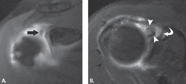
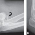
FIGURE 6.13 Complete rupture of biceps tendon with free stump. Coronal (A) intermediate-weighted fat-suppressed MR image shows the anteriorly displaced torn proximal biceps tendon (arrow). Axial (B) T2-weighted fat-suppressed MR image profiles the torn proximal biceps tendon (arrowheads) that is anteriorly displaced and residing anterior to the superior glenohumeral ligament (curved arrow).
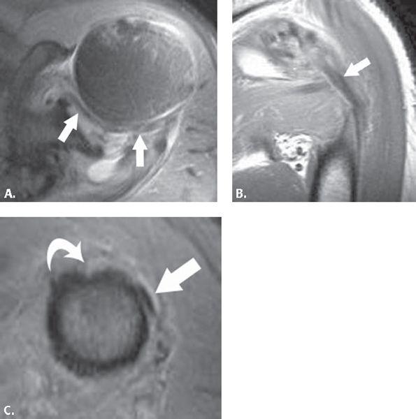
FIGURE 6.14 Posterior dislocation of the biceps tendon. Axial (A) proton density-weighted fat-suppressed MR image in a trauma patient shows incarceration of the biceps (arrows) and within the joint as it courses posteriorly. Coronal (B) proton density-weighted MR image shows posterior displacement of the biceps tendon (arrow). Axial (C) proton density-weighted MR image at the proximal humeral shaft shows the biceps (arrow) coursing from a posterior position toward the intertubercular sulcus (curved arrow).
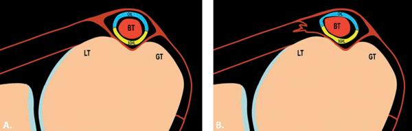
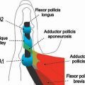
FIGURE 6.15 Diagrams of normal-appearing biceps tendon (A) and type I biceps tendon instability (B). In the normal situation, at the superior aspect of the lesser tuberosity, the biceps resides within and is located in the center of the intertubercular sulcus stabilized by the fibers of the biceps pulley, coracohumeral ligament (CHL) superficially, and superior glenohumeral ligament (SGHL) deep to the tendon. The subscapularis tendon attaches to the lesser tuberosity (LT) and gives fibers that pass superficial to the intertubercular sulcus attaching at the greater tuberosity (GT) as well as fibers that pass deep to the biceps tendon and pulley en route to the greater tuberosity (GT). In type I instability (B), a partial intrasubstance tear of the subscapularis with an intact pulley can result in minimal medial shift of the biceps tendon.
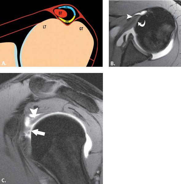
FIGURE 6.16 Type II biceps tendon instability. Diagram (A) shows an intact subscapularis tendon attachment to lesser (LT) and greater tuberosities (GT) but insufficiency of the biceps pulley and medial subluxation of the biceps. Axial (B) and sagittal (C) T1-weighted fat-suppressed MR images after intra-articular contrast administration show the medial subluxation of the biceps (arrowhead), the intact subscapularis tendon attachment (curved arrow), and irregularity of the biceps pulley (arrow) consistent with partial tearing.
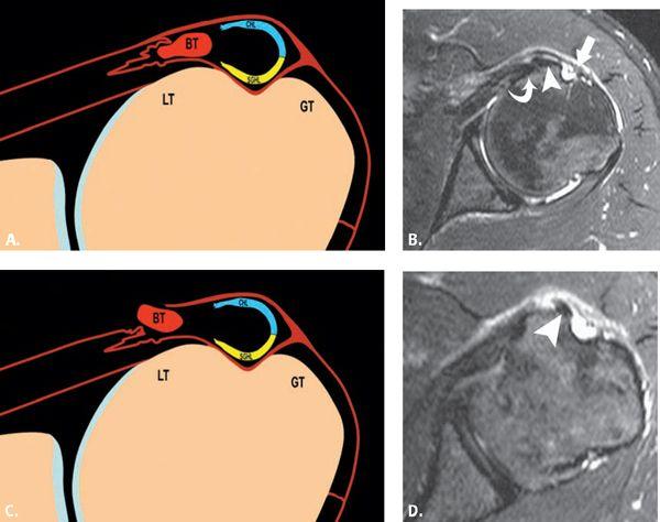
FIGURE 6.17 Types IIIA and B biceps tendon instability. Diagram (A) shows extra-articular tendon dislocation with tears of the biceps pulley as well as an intrasubstance tear of the subscapularis tendon. In type IIIA, the dislocated biceps resides within the subscapularis tendon. Axial (B) intermediate-weighted fat-suppressed MR image shows the intact articular-sided (curved arrow) and superficial (arrow) components of the subscapularis. The biceps (arrowhead) is dislocated into the fibers of the subscapularis with an empty intertubercular sulcus. Diagram (C) of the type IIIB lesion differs in that the biceps dislocates to an extra-articular position through a bursal-sided tear. Axial (D) intermediate-weighted fat-suppressed MR images show the extra-articular dislocation of the biceps tendon (arrowhead) through a bursal-sided tear of the subscapularis tendon.
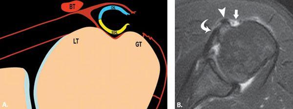
FIGURE 6.18 Type IV biceps tendon instability. Diagram (A) shows extra-articular tendon dislocation with tears of the lateral limbs of the biceps pulley and an intact subscapularis tendon. Axial (B) T2-weighted fat-suppressed MR image shows the intact lesser tuberosity attachment of the subscapularis (curved arrow), the dislocated biceps tendon (arrowhead), and the gap (arrow) between the torn superficial subscapularis fibers and the greater tuberosity.
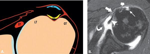
FIGURE 6.19 Type V biceps tendon instability. Diagram (A) demonstrates intra-articular tendon dislocation with tears of the pulley and a focal full-thickness tear of the subscapularis. Axial (B) T2-weighted fat-suppressed MR image shows a full-thickness tear of the subscapularis with differential retraction of the undersurface fibers of the tendon (curved arrow). The gap between the discontinuous superficial fibers is noted (between long and short arrows). The biceps tendon (arrowhead) is displaced into the joint, and the intertubercular sulcus (thin arrow) is empty.
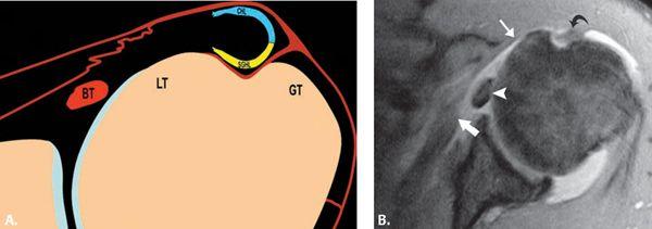
FIGURE 6.20 Type VI biceps tendon instability. Diagram (A) demonstrates intra-articular biceps tendon dislocation with biceps pulley insufficiency and detachment of the subscapularis tendon, although continuing fibers of the subscapularis to greater tuberosity remain intact. Axial (B) T2-weighted fat-suppressed MR image shows intra-articular dislocation of the biceps tendon (arrowhead). There is differential retraction of the lesser tuberosity attachment of the subscapularis (thick arrow), whereas the thin superficial continuation of the subscapularis (thin arrow) isintact. It appears slightly thickened (curved arrow) as it crosses the intertubercular sulcus.
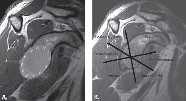
FIGURE 6.21 Labral localization. Labral position can be described by referring to position as determined by superimposing the face of a clock onto the glenoid (A) or by referring to regions (B) of the glenoid attachment.
Biceps tendon subluxations and dislocations can be identified by ultrasound (32), computed tomography, arthrography, and MRI. This can be seen in all imaging planes on MRI but is easiest to identify on axial images (14, 15, 32, 33). Axial MR images obtained with internal and external rotation may bring out subtle subluxation and dislocation, but most are readily apparent on routine axial MR images.
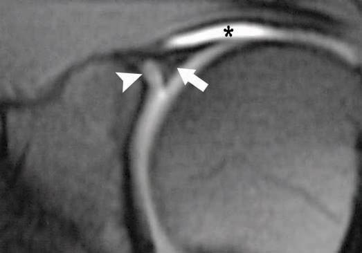
FIGURE 6.22 Histologic zone of labrum. Coronal T1-weighted fat-suppressed MR image obtained after intra-articular administration of contrast shows intermediate signal intensity (arrowhead) between the labrum (arrow) and glenoid margin. This signal is similar to that of articular cartilage and much less bright than dilute contrast material (asterisk) within the joint. This represents the normal undercutting of the fibrocartilaginous labrum with articular cartilage.
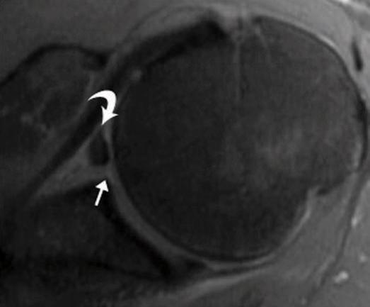
FIGURE 6.23 Buford complex. Axial T2-weighted fat-suppressed MR image showing a large middle glenohumeral ligament (curved arrow) with an absent anterior superior labrum.
Superior Labral Anterior–posterior Lesions
SLAP tears are a common cause of labral pathology, leading to shoulder pain and instability. Arthroscopic studies have reported a prevalence of SLAP lesions of 3.9% to 11.8%. Snyder and Karzel (33) analyzed 700 shoulder arthroscopies and found a SLAP incidence of 3.9%. Maffet and Moseley (34) identified 84 SLAP-type lesions in 712 consecutive shoulder arthroscopies, constituting an incidence rate of 11.8%. A SLAP lesion is an acquired abnormality of the labrum, usually centered on the attachment of the long head of biceps tendon. It can extend to involve the anterior and posterior labrum as well as the surrounding anatomic structures. Andrews et al. (35) first described detachment and fraying of the anterior superior labrum, which may be accompanied by partial tearing of the biceps tendon, in a group of high-level throwing athletes. The term SLAP was subsequently coined by Snyder et al. (36), who described a similar but more global injury of the superior labrum that extended anterior and posterior to the biceps tendon. Diagnosis of a SLAP lesion can be difficult clinically, and imaging plays a key role in its detection.
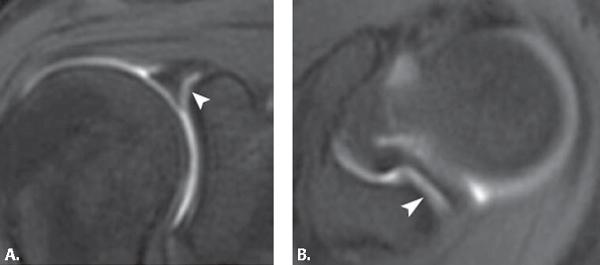
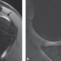
FIGURE 6.24 Sublabral recess/sulcus. Coronal (A) and axial (B) T1-weighted fat-suppressed MR arthrogram images show contrast (arrowhead) collecting between the superior labrum and the glenoid in the distribution of 10 to 2 o’clock. There is no widening or irregularity of the space. The space follows the contour of the superior glenoid margin.
Clinical Presentation, Etiology, and Physical Examination
The clinical diagnosis of a SLAP lesion is difficult. Non-specific shoulder pain, particularly with overhead or cross-body motion, is the most common clinical presentation. Additional symptoms include popping, clicking, catching, weakness, stiffness, and instability. The majority of patients present with concurrent shoulder injuries. In a retrospective review of 140 arthroscopically proven SLAP lesions by Snyder and Karzel (35), the reported incidence of associated intra-articular disease included 29% with partial rotator cuff tears, 11% with full rotator cuff tears, 22% with Bankart lesions, and 10% with glenohumeral chondromalacia.
Clinical history may involve a traction injury, direct trauma to the shoulder, or fall on an outstretched arm. Frequently, no antecedent injury or activity is reported. On physical examination, the patient may have increased shoulder laxity and positive findings with many provocative shoulder tests. No single physical test or sign is specific for SLAP lesions and physical findings can be confusing as a result of associated lesions (e.g., rotator cuff tears). The clinical diagnosis of a SLAP lesion is difficult and imaging plays a key role in diagnosis.
Recently, a cadaveric study has confirmed the peel-back theory of SLAP lesions. In the abducted and externally rotated shoulder, the biceps tendon assumes a more vertical and posteriorly directed orientation, which transmits a force to the superior labrum, causing it to peel off the glenoid (39). Common mechanisms of injury include microtrauma secondary to repetitive overhead arm motion and direct trauma resulting from falling on an outstretched hand. Repetitive overhead arm motions such as those used in throwing and swimming are thought to cause injury secondary to traction on the arm as a result of sudden pulling, throwing, or other overhead motion (36). Additional findings in repetitive overhead motion injury include undersurface rotator cuff tears, cystic change in the humeral head related to posterosuperior impingement, and capsular laxity. Falling on an outstretched arm causes injury secondary to compressive force applied to the shoulder, usually with the shoulder abducted and slightly anteriorly flexed (38). This mechanism can result in marrow edema secondary to impaction of the humeral head against the glenoid. If an associated anterior dislocation is present, a Hill-Sachs deformity and a Bankart lesion may occur.
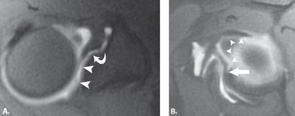
FIGURE 6.25 Sublabral hole/foramen. Axial (A) and sagittal (B) T1-weighted fat-suppressed MR arthrogram images show contrast separating the superior (arrowheads) and anterior (curved arrow) labrum from the adjacent glenoid. The presence of labral slip (B) (straight arrow), labral tissue that extends back to the glenoid, is very compelling for the diagnosis of a sublabral hole or foramen.
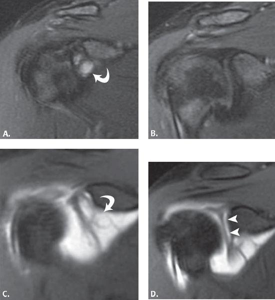
FIGURE 6.26 Superior labral anterior–posterior (SLAP) pathology with and without intra-articular contrast. Sequential coronal (A–B) T2-weighted fat-suppressed MR images show a complex perilabral cyst (curved arrow) adjacent to the anterior superior labrum. Follow-up sequential coronal (C–D) T1-weighted fat-suppressed MR arthrogram images show the perilabral cyst filled with contrast (curved arrow) as well as the gross separation of the labrum from the anterior glenoid (arrowheads). In some cases, distention of the capsule is very helpful for both the diagnosis and characterization of labral pathology.
Anatomy of the Superior Capsulolabral Complex
The labrum is a fibrocartilaginous structure that forms a cuff around the periphery of the glenoid. The labrum deepens the glenoid fossa and provides shoulder stability. It serves as the attachment for the glenohumeral ligaments and the tendon of the long head of the biceps muscle to the glenoid. A basket of capsular fibers, designated the periarticular fibers system, extends around the neck of the scapula and encompasses contributions from these tissues. Anteriorly, the labrum blends with the anterior band of the inferior glenohumeral ligament (IGHL). Superiorly, it blends with the biceps tendon and SGHL. The labrum is variable in shape, size, and attachment to the glenoid (40). The labrum is usually rounded or triangular. Its superior portion is more loosely attached and more mobile than the rest of the labrum. This normal laxity can be confused with SLAP lesions. The labrum normally displays low signal on all MR sequences.
For descriptive purposes, labral position is localized by superimposing the face of a clock onto the surface of the glenoid and, by convention, 3 o’clock is anterior, 9 o’clock is posterior, 12 o’clock is superior, and 6 o’clock is inferior. An alternative is to divide the labrum into six segments: superior, anterosuperior, anteroinferior, inferior, posteroinferior, and posterosuperior (Fig. 6.21).
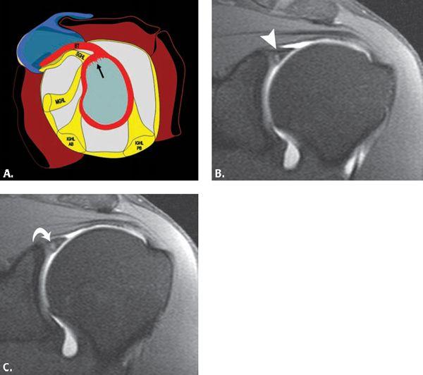
FIGURE 6.27 Superior labral anterior–posterior (SLAP) I. Diagram (A) showing superior labral fraying. Sequential coronal T1-weighted fat-suppressed MR arthrogram images show contrast within the anterior (arrowhead) and more posterior (curved arrow) superior labral substance consistent with SLAP I pathology.
Normal Variants of the Superior and Anterosuperior Labrum
The area of greatest anatomic variation in the labrum is between the 11 and 3 o’clock positions. This variability frequently poses a diagnostic challenge because it is also a common location for pathology. Variations can occur in signal intensity, morphology, attachment, and presence or absence of the anterior–superior labrum. Normal variants include the sublabral recess or sulcus, the sublabral foramen or hole, the Buford complex, and other less common variants.
The normal signal intensity of the labrum is low signal on all pulse sequences. The labral signal can be variable with increased signal, particularly in older individuals. The clinical significance of high signal is unclear, particularly if the underlying morphology of the labrum is normal. The signal characteristics could be a variant of normal or represent early degenerative or posttraumatic changes. High signal that follows the contours of the superior glenoid margin can be a normal appearance of the labrum representing the histologic transitional area from fibrocartilage of the labrum to hyaline cartilage of the glenoid (Fig. 6.22). This cartilage interface is found particularly in the superior half of the glenohumeral joint. It is distinguished from pathology in that its signal does not extend into the labral substance.
The most common shape of the labrum is triangular or rounded on cross-sectional images; however, the morphology of the normal labrum is also quite variable. Globular or irregular morphology can be a sign of a tear or degenerative changes. Smooth margins of the labrum, regardless of the labral morphology, are more likely to be associated with a normal variant versus the irregular margins of labral pathology.
A Buford complex, found in 1.5% of individuals (41), is the absence of the anterior–superior labrum in conjunction with a thickened cord-like middle glenohumeral ligament (MGHL). The thick MGHL attaches directly to the anterosuperior glenoid (Fig. 6.23). It can be confused with a sublabral hole or pathologic labral detachment. If mistakenly surgically reattached to the neck of the glenoid cartilage, severe painful restriction of humeral rotation and elevation can occur.
The sublabral sulcus, or recess (Fig. 6.24), is usually confined to the superior labrum at the 11 to 1 o’clock position at the site of attachment of the long head of the biceps tendon. It is a sulcus between the capsulolabral complex and the superior glenoid cartilage. Conventionally, it does not extend behind the biceps anchor, although recent research has revealed that this configuration is not uncommon (42). The normal sulcus has smooth edges and usually measures less than 2 mm in width.
The sublabral hole, or foramen, is located anterior to the biceps tendon attachment and involves the anterior labrum (Fig. 6.25). Typically, a foramen is located from the 12 o’clock to the 2 o’clock position (43). It is found in 11% to 15% of patients (41, 44, 45). The sublabral hole has smooth edges. A key finding to identifying a hole versus a tear is a medial slip that courses medially and posteriorly toward the glenoid and attaches to the anterior labrum more inferiorly. In contrast, a tear is usually oriented laterally, away from the glenoid.
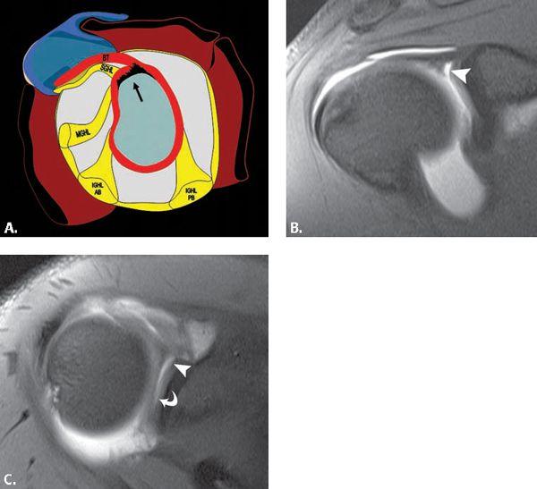
FIGURE 6.28 Superior labral anterior–posterior (SLAP) II. Diagram (A) showing an abnormal labral detachment and labral fraying in the 10 to 2 o’clock distribution. Coronal (B) T1-weighted fat-suppressed MR arthrogram image shows a widened gap (arrowhead) between the superior labrum and adjacent glenoid. Corresponding axial (C) T1-weighted fat-suppressed MR arthrogram verifies the presence of the labral detachment and profiles the widening of the anterior (arrowhead) space as compared with the more posterior (curved arrow) space, very characteristic of SLAP pathology.
Related posts:

Stay updated, free articles. Join our Telegram channel

Full access? Get Clinical Tree


