Fig. 11.1
A 3D image of a normally functioning, trileaflet, Biocor bioprosthetic mitral valve replacement viewed from the left atrium. High image resolution enables the leaflets, annulus, and even sutures to be clearly demonstrated. The 3D image is conventionally orientated with the aortic valve at the 12 o’clock position, thereby allowing consistency of image description and better ease of interpretation
Video 11.1 A 3D image of a normally functioning, trileaflet, Biocor bioprosthetic mitral valve replacement viewed from the left atrium. High image resolution enables the leaflets, annulus, and even sutures to be clearly demonstrated. The 3D image is conventionally orientated with the aortic valve at the 12 o’clock position, thereby allowing consistency of image description and better ease of interpretation (AVI 1528 kb)
11.1 Case 1. Alfieri Stitch
A 70-year-old woman presented with long-standing mitral regurgitation, aortic regurgitation, and paroxysmal atrial fibrillation. She demonstrated increasing left atrial and left ventricular enlargement, which prompted surgical referral. Despite prominent mitral annular calcification, the surgeon was able to successfully repair her mitral valve, using plication of the middle scallop of the posterior leaflet, an Alfieri stitch, and placement of a 35-mm annuloplasty ring. She also underwent replacement of the aortic valve with a #23 Carpentier-Edwards bovine pericardial heterograft, isolation of the pulmonary veins, and ligation of the left atrial appendage (Figs. 11.2, 11.3, 11.4, and 11.5).
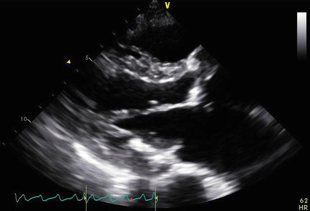
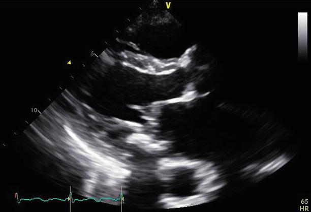
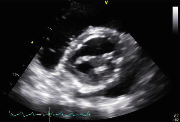
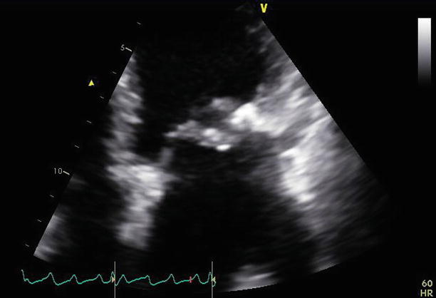

Fig. 11.2
A parasternal long-axis view demonstrates the repaired mitral valve, with the aortic valve replacement in situ

Fig. 11.3
Slight angulation of the probe demonstrates a parasternal long-axis view of the mitral valve at the position of the Alfieri stitch. This appearance may be mistaken for mitral stenosis. The annuloplasty ring in short axis can be best appreciated at the posterior aspect of the annulus

Fig. 11.4
A parasternal short-axis view at the left ventricular base demonstrates the double-orifice mitral valve with the Alfieri stitch joining the middle aspects of both mitral valve leaflets and improving overall leaflet coaptation

Fig. 11.5
The mitral valve is viewed from an apical four-chamber view. The Alfieri stitch can be seen joining the leaflet tips centrally. The annuloplasty ring is appreciated laterally. The posterior leaflet appears small and somewhat restricted, consistent with the known repair and plication of the middle posterior scallop
Video 11.2 A parasternal long-axis view demonstrates the repaired mitral valve, with the aortic valve replacement in situ (AVI 2992 kb)
Video 11.3 Slight angulation of the probe demonstrates a parasternal long-axis view of the mitral valve at the position of the Alfieri stitch. This appearance may be mistaken for mitral stenosis. The annuloplasty ring in short axis can be best appreciated at the posterior aspect of the annulus (AVI 2244 kb)
Video 11.4 A parasternal short-axis view at the left ventricular base demonstrates the double-orifice mitral valve with the Alfieri stitch joining the middle aspects of both mitral valve leaflets and improving overall leaflet coaptation (AVI 3100 kb)
Video 11.5 The mitral valve is viewed from an apical four-chamber view. The Alfieri stitch can be seen joining the leaflet tips centrally. The annuloplasty ring is appreciated laterally. The posterior leaflet appears small and somewhat restricted, consistent with the known repair and plication of the middle posterior scallop (AVI 2712 kb)
11.2 Case 2. Valvuloplasty
A 43-year-old woman in previously excellent health presented with a cerebrovascular accident due to middle cerebral artery occlusion. She was emergently treated with fibrinolysis and achieved full recovery. She subsequently was found to have severe mitral stenosis, despite an absence of previous symptoms. The transvalvular peak gradient was 23 mmHg and the mean gradient was 14 mmHg, with moderate (2–3+) mitral regurgitation. She was anticoagulated and then referred for mitral balloon valvuloplasty, which was performed via a trans-septal puncture. After the procedure, the gradients were reduced to 16 and 9 mmHg, with only mild (1+) residual mitral regurgitation, and the estimated mitral valve area (by pressure half time) was 1.9 cm2 (Figs. 11.6, 11.7, 11.8, 11.9, 11.10, 11.11, 11.12, and 11.13).
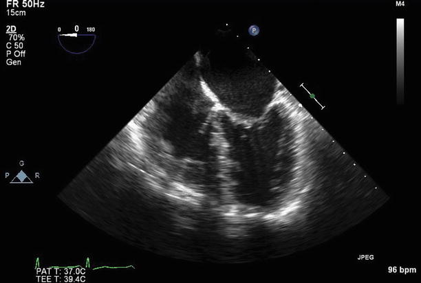
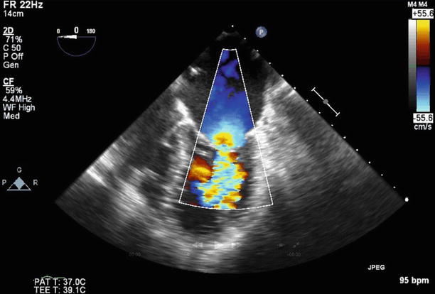
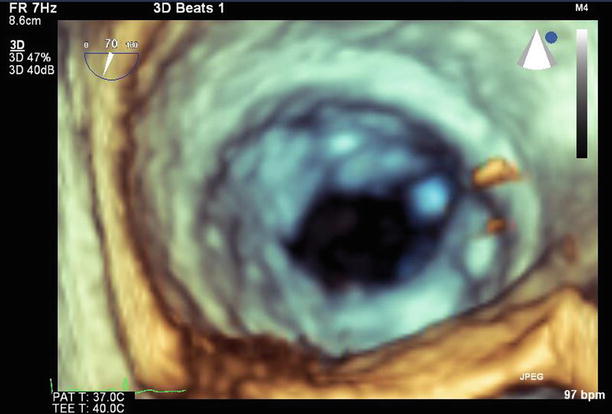
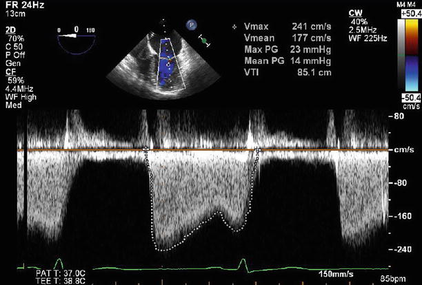
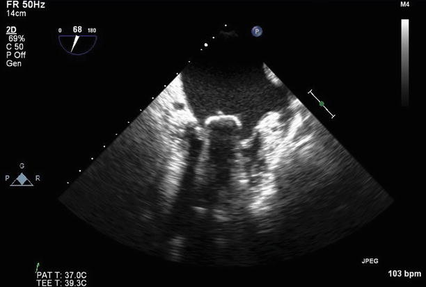
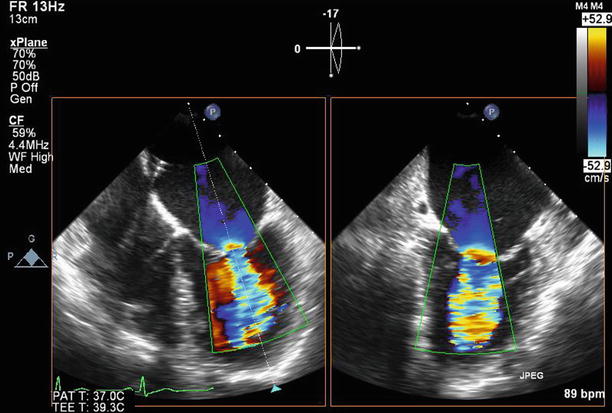
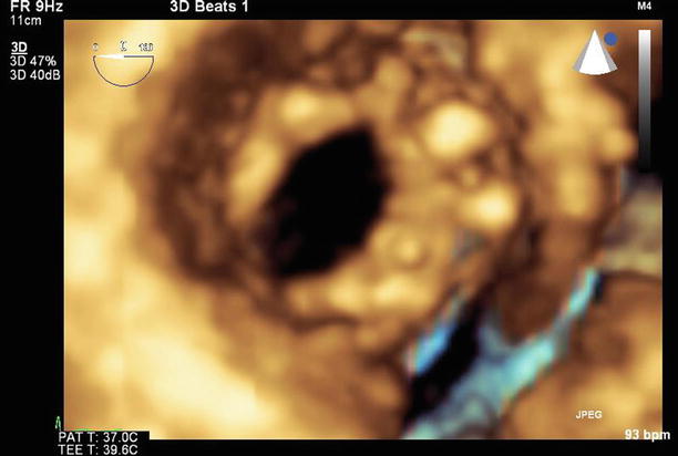
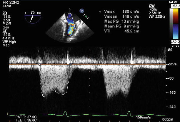

Fig. 11.6
Transesophageal echocardiogram (TEE) at 0°, demonstrating severe thickening and tethering of both mitral valve leaflets (predominantly involving the leaflet tips). This appearance is typical for rheumatic heart disease

Fig. 11.7
TEE at 0° demonstrating moderate (2–3+) regurgitation at baseline. A septostomy has been performed in preparation for the valvuloplasty, and the catheter can be seen traversing the interatrial septum

Fig. 11.8
3D image of the mitral valve viewed from the left atrium. The leaflets are thickened, with commissural fusion and a resultant reduced valve area

Fig. 11.9
Continuous wave Doppler through the mitral valve demonstrates severe stenosis with a peak gradient of 23 mmHg and a mean gradient of 14 mmHg

Fig. 11.10
Balloon inflation within the mitral valve at the time of valvuloplasty

Fig. 11.11
After valvuloplasty, biplane color Doppler imaging through the mitral valve demonstrates no significant increase in severity of mitral regurgitation from baseline

Fig. 11.12
A 3D image of the mitral valve (viewed from the left atrium) after valvuloplasty shows that leaflet mobility has improved, with a reduction in commissural fusion and an increased valve area

Fig. 11.13
Continuous wave Doppler through the mitral valve after valvuloplasty demonstrates an improvement in transmitral gradients to a peak of 13 mmHg and a mean of 9 mmHg
Video 11.6 Transesophageal echocardiogram (TEE) at 0°, demonstrating severe thickening and tethering of both mitral valve leaflets (predominantly involving the leaflet tips). This appearance is typical for rheumatic heart disease (AVI 4855 kb)
Video 11.7 TEE at 0° demonstrating moderate (2–3+) regurgitation at baseline. A septostomy has been performed in preparation for the valvuloplasty, and the catheter can be seen traversing the interatrial septum (AVI 1992 kb)
Video 11.8 A 3D image of the mitral valve viewed from the left atrium. The leaflets are thickened, with commissural fusion and a resultant reduced valve area (AVI 1077 kb)
Video 11.9 Balloon inflation within the mitral valve at the time of valvuloplasty (AVI 6410 kb)
Video 11.10 After valvuloplasty, biplane color Doppler imaging through the mitral valve demonstrates no significant increase in severity of mitral regurgitation from baseline (AVI 1806 kb)
Video 11.11 A 3D image of the mitral valve (viewed from the left atrium) after valvuloplasty shows that leaflet mobility has improved, with a reduction in commissural fusion and an increased valve area (AVI 1272 kb)
11.3 Case 3. Paravalvular Leak 1
A 62-year-old woman with end-stage renal failure on hemodialysis presented with a severe paravalvular mitral valve leak, severe tricuspid regurgitation, and moderate aortic stenosis on a background history of previous bioprosthetic mitral valve replacement and coronary artery bypass graft surgery 3 years earlier. She underwent a mitral valve replacement with an On-X mechanical valve (#33), a tricuspid valve repair with a Carpentier ring (#30), an aortic valve replacement with a Trifecta bioprosthesis (#23), and coronary artery bypass graft surgery.
Preoperative echocardiography demonstrated a paravalvular leak originating at the anterolateral aspect of the mitral annulus. The eccentric, regurgitant jet hugged the wall of the left atrium and was difficult to quantitate, but visually it appeared severe. Transvalvular peak and mean gradients of 17 and 9 mmHg were noted (Figs. 11.14, 11.15, and 11.16).
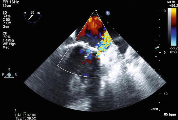
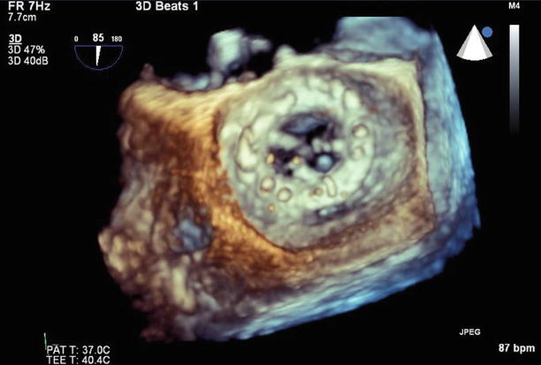
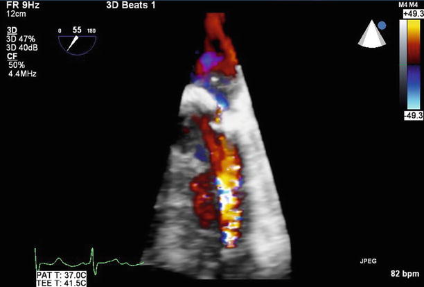

Fig. 11.14
TEE at 50° demonstrates an eccentric paravalvular leak originating at the anterolateral aspect of the mitral annulus

Fig. 11.15
With 3D reconstruction of the mitral valve, orientated with the aortic valve at the top of the image, the small paravalvular defect can be seen adjacent to the valve annulus at the 6 o’clock position

Fig. 11.16
3D color Doppler imaging clearly demonstrates the small paravalvular leak
Video 11.12 TEE at 50° demonstrates an eccentric paravalvular leak originating at the anterolateral aspect of the mitral annulus (AVI 1485 kb)
Video 11.13 With 3D reconstruction of the mitral valve, orientated with the aortic valve at the top of the image, the small paravalvular defect can be seen adjacent to the valve annulus at the 6 o’clock position (AVI 845 kb)
Video 11.14 Color 3D imaging clearly demonstrates the small paravalvular leak (AVI 953 kb)
11.4 Case 4. Paravalvular Leak 2
A 51-year-old woman with a past history of mitral valve replacements 20 and 27 years previously now presents with hemolytic anemia, atrial fibrillation, and a small (5 mm) mitral paravalvular leak with severe tricuspid regurgitation. She has symptoms of right heart failure with evidence of fluid overload. She has known biventricular dysfunction, with implantation of an implantable cardiac defibrillator.
Echocardiography demonstrated biventricular enlargement. The St. Jude mechanical prosthetic mitral valve replacement was associated with a moderate (2–3+), posterolaterally directed paravalvular leak, which originated adjacent to the lateral aspect of the valve near the left atrial appendage ostium, although the valve itself remained well seated. There was severe (4+) tricuspid regurgitation related to annular dilatation.
She successfully underwent her third cardiac surgery involving mitral valve replacement with an On-X mechanical valve (#33) and a tricuspid valve repair with a Carpentier classic annuloplasty ring (#30) (Figs. 11.17, 11.18, 11.19, and 11.20).
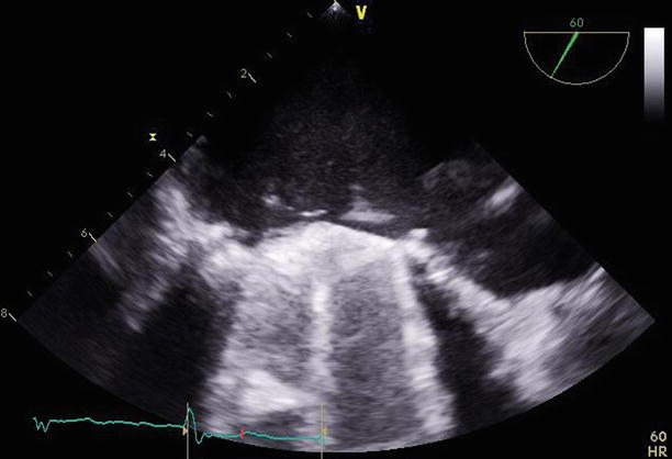
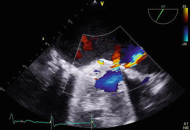
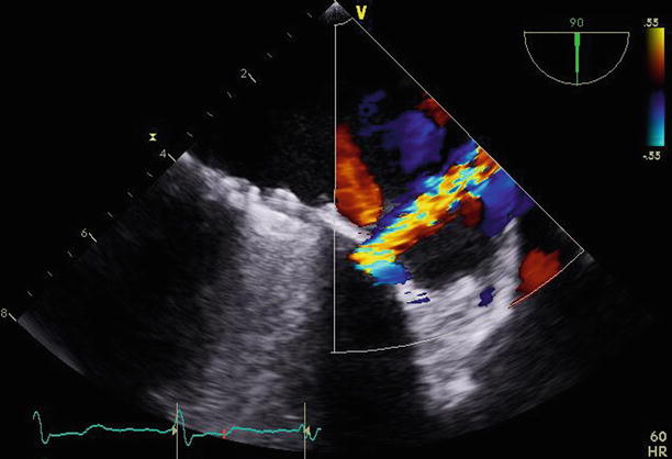
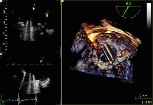

Fig. 11.17
TEE at 60° demonstrating the mechanical mitral valve with normally functioning leaflets. A small paravalvular region of defect can be seen adjacent to the lateral aspect of the valve

Fig. 11.18
The same 60° transesophageal view demonstrates a small jet of flow through the paravalvular defect on color Doppler imaging

Fig. 11.19
Rotating the transesophageal probe to 90° demonstrates the paravalvular leak adjacent to the lateral aspect of the valve, perpendicular to the orifice of the left atrial appendage

Fig. 11.20
3D imaging (right-hand panel) of the mechanical mitral valve demonstrates a normally functioning, well-seated bileaflet prosthesis
Video 11.15 TEE at 60° demonstrating the mechanical mitral valve with normally functioning leaflets. A small paravalvular region of defect can be seen adjacent to the lateral aspect of the valve (AVI 8981 kb)
Video 11.16 The same 60° TEE view demonstrates a small jet of flow through the paravalvular defect on color Doppler imaging (AVI 1539 kb)
Video 11.17 Rotating the TEE probe to 90° demonstrates the paravalvular leak adjacent to the lateral aspect of the valve, perpendicular to the orifice of the left atrial appendage (AVI 1689 kb)
Video 11.18 3D imaging of the mechanical mitral valve demonstrates a normally functioning, well-seated bileaflet prosthesis (AVI 1277 kb)
11.5 Case 5. Paravalvular Leaks 3
A 67-year-old woman presented with mild exertional dyspnea and mild hemolytic anemia. Her background history included myxomatous mitral valve disease, for which she underwent mitral valve replacement over 10 years ago, followed by replacement with a porcine valve and tricuspid repair 3 years ago.
Transthoracic and transesophageal echocardiograms were remarkable for a moderate (2+), anterolateral mitral paravalvular leak, although the mitral valve prosthesis appeared otherwise well-seated. The vena contracta measured 0.1 cm2. Otherwise, there was only trivial valvular regurgitation, with no restriction of leaflet excursion. The peak and mean gradients were 22 and 6 mmHg. The tricuspid valve repair appeared intact, with only trivial regurgitation and a mean gradient of 4 mmHg (Figs. 11.21, 11.22, 11.23, and 11.24).
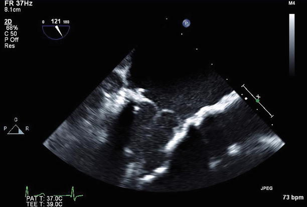
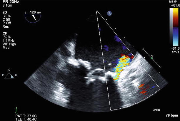
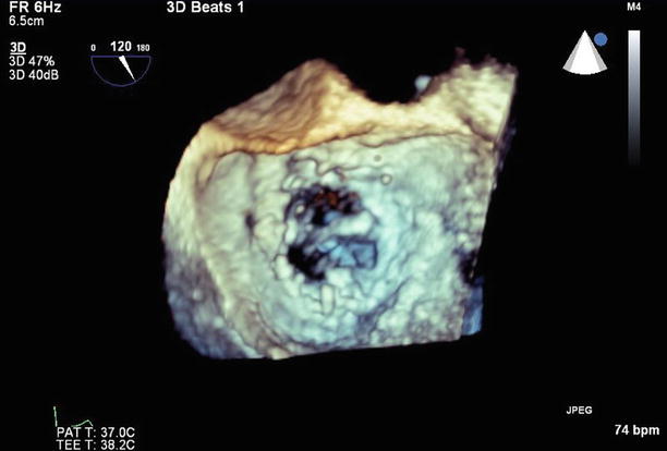
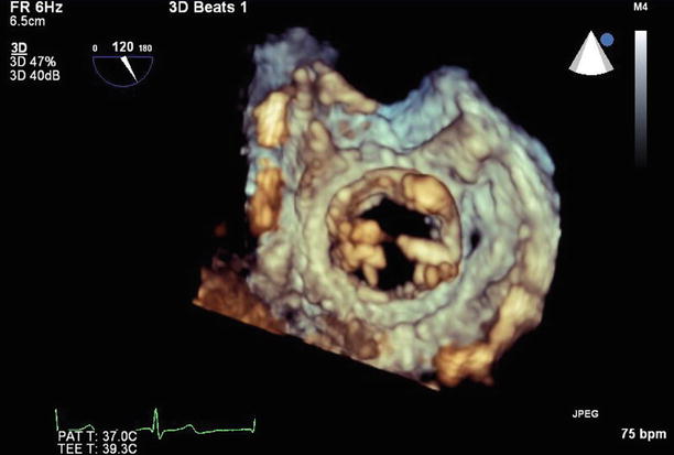

Fig. 11.21
TEE long-axis view demonstrating a normally functioning bioprosthetic mitral valve replacement

Fig. 11.22
TEE long-axis view with a moderate (2+) paravalvular leak anteriorly on color Doppler imaging

Fig. 11.23
3D left atrial view of the mitral valve, atypically orientated with the aortic valve at 3 o’clock and the anterior paravalvular defect at the 9 o’clock position

Fig. 11.24
3D left ventricular view of the mitral valve, with the anterior paravalvular defect now visible at the 3 o’clock position
Given her lack of symptoms and only mild anemia, she will have ongoing follow-up with serial echocardiography every 6–12 months, or sooner if her symptoms worsen.
Video 11.19 Transesophageal long-axis view demonstrating a normally functioning bioprosthetic mitral valve replacement (AVI 4234 kb)
Video 11.20 Transesophageal long-axis view with a moderate (2+) paravalvular leak anteriorly on color Doppler imaging (AVI 2679 kb)
Video 11.21 3D left atrial view of the mitral valve, atypically orientated with the aortic valve at 3 o’clock and the anterior paravalvular defect at the 9 o’clock position (AVI 745 kb)
Video 11.22 3D left ventricular view of the mitral valve, with the anterior paravalvular defect now visible at the 3 o’clock position (AVI 755 kb)
11.6 Case 6. Bioprosthetic Mitral Valve Replacement and Pseudoaneurysm
A 77-year-old woman was referred with a history of coronary artery bypass graft surgery and bioprosthetic aortic (#21) and mitral (#25) valve replacements for aortic stenosis and mitral regurgitation 2 months earlier. The surgery had been complicated by severe mitral annular calcification and bleeding from the AV groove and posterior ventricle, which required a pericardial patch. She now reported worsening symptoms of heart failure, and echocardiography demonstrated partial dehiscence of the mitral valve with a resultant severe, posterior paravalvular leak (measuring 1.0 cm in maximal diameter), which was in direct communication with a large (5.0 × 4.1 cm) pseudoaneurysm adjacent to the left atrium, which obstructed pulmonary venous drainage (Figs. 11.25, 11.26, 11.27, and 11.28). The aortic valve replacement was well seated, with only trivial regurgitation. Reoperation was performed involving removal of the old prosthesis, unroofing and repair of the pseudoaneurysm, and replacement of the mitral valve with a Biocor #29 prosthesis.
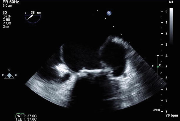

Fig. 11.25


TEE imaging of the bioprosthetic mitral valve replacement at 38°, demonstrating the large pseudoaneurysm adjacent to the valve annulus and left atrium laterally
Stay updated, free articles. Join our Telegram channel

Full access? Get Clinical Tree


