Fig. 9.1
(a) Carbon ion beam dose distribution in and out of the gating window. (b) A pencil beam stopped at the tumor at diastole, but caused overshoot at systole [1]
An understanding of motion characteristics in radiotherapy planning is useful for determining internal margins and optimizing beam parameters (beam angle, beam field and beam energy, etc.). Organ motion due to respiration has been investigated using a variety of methods, including fluoroscopy, ultrasound (US), MRI, CT, and PET, in the lung, liver, pancreas, kidney, and prostate sites.
We quantified organ motions due to respiration in thoracic, abdominal, and pelvic sites as a function of time using 4DCT. For pancreas, geometrical variation was greater around the pancreas tail than the pancreas body and head regions. The average pancreas head, body, and tail displacement in the inferior direction for the ungated phase was 8.3, 9.6, and 13.4 mm, respectively, which was minimized in the gated phase to 2.8, 2.8, and 3.6 mm, respectively. For all six patients with pancreatic cancer, the average pancreas center of mass (COM) displacement relative to that at peak exhalation was mainly in the inferior direction, at 9.6 mm for the ungated phase and 2.3 mm for the gated phase [2].
With regard to the liver site (irradiation administered with patients in the prone position), geometrical changes due to respiration were quantified by a deformable image registration between the reference and respective respiratory phases. The magnitude of the intrafractional displacement was increased close to the inhalation phase, with both AP and SI movement around the diaphragm. The GTV-COM displacement average in ten patients was 0.3 mm (max, 1.8 mm) in the left side, 2.2 mm (max, 5.3 mm) in the right side, 4.6 mm (max, 10.8 mm) in the anterior side, 0.1 mm (max, 0.3 mm) in the posterior side, and 11.6 mm (max, 17.4 mm) in the inferior side. No displacement was observed on the superior side.
For lung cases, a total of 14 lung cancer patients participated in the 4DCT immobilization study (supine position only). Although most tumors moved in a varying orbit during the respiratory cycle, showing hysteresis-like behavior, some moved in a closely similar orbit (Fig. 9.2). Therefore, it is important to evaluate tumor motion in 3D axis. The average GTV-COM displacement relative to that at peak exhalation was 1.4 mm (range 0.5–2.3 mm) in the left–right, 2.2 mm (range 0.8–4.7 mm) in the anterior–posterior, and 6.6 mm (range 1.6–21.8 mm) in the superior–inferior direction (3).
Twenty inpatients exhibited prostate displacement as a function of respiratory phase. Less than 1 mm of prostate COM moved in the superior, inferior, and posterior directions mainly due to intrafractional respiratory motion [3]. Therefore, we did not perform the gated prostate treatment. We have not yet compared prostate movements with and without immobilization, although these small displacements might be affected by immobilizing the patients as seen in the lung cases [4].
In clinical situations, it takes several minutes to complete treatment beam irradiation per fraction using the respiratory-gated strategy. Triple-phase dynamic enhancement CT acquisitions were routinely acquired for diagnostic purposes under inhalation breath-holding. The CT scan interval time of the venous phase and delayed phase from the arterial phase were 35 and 145 s, respectively. We defined the arterial phase CT data (scan interval time 0 s) as a treatment planning CT and calculated the compensating bolus, which was then applied to the CT data sets at the other two phases. Since the bolus was designed to cover the CTV at the planning CT, over 95 % of the dose was delivered to the CTV at 0 s. Although anatomical positions at each phase were similar, beam overshoot/undershoot was observed at 35 and 145 s due to extension/shortening of the radiological path length from the anterior and left directions against the planning CT. Since gas bubbles in the bowel may degrade dose conformation to the target, methods to appropriately deal with this issue are required (Fig. 9.3).
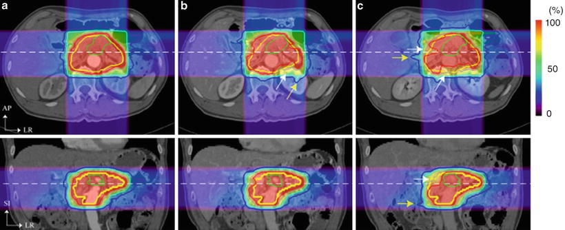
Fig. 9.2
3D visualization of tumor isocenter displacement for the right lung. Respiratory cycle and distance between PE and PI are shown in parentheses [5]. By permission of Elsevier
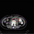
Fig. 9.3
Carbon ion beam distribution in axial and coronal sections (patient no. 1). Time of (a) 0 s (planning CT), (b) 35 s, and (c) 145 s. Beam overshoot (yellow arrows) and undershoot (white arrows) were observed at the scan interval time of 35 and 145 s. Green and yellow lines show GTV and CTV contours, respectively. Red, pink, light-blue, and blue lines show 95, 80, 50, and 30 % of doses, respectively [6]. By permission of Elsevier
9.2 Treatment Planning
A respiratory-gated CT scan was developed to minimize geometrical errors due to respiratory motion in the treatment planning stage. It acquires at the most reproducible respiratory phase only (in general, this is at peak exhalation) using respiratory monitoring system (details are described later) (Fig. 9.4a). When a quality of the gated-CT image was degraded due to irregular respiratory pattern at the couch position, gated CT was retried to acquire at the same couch position.
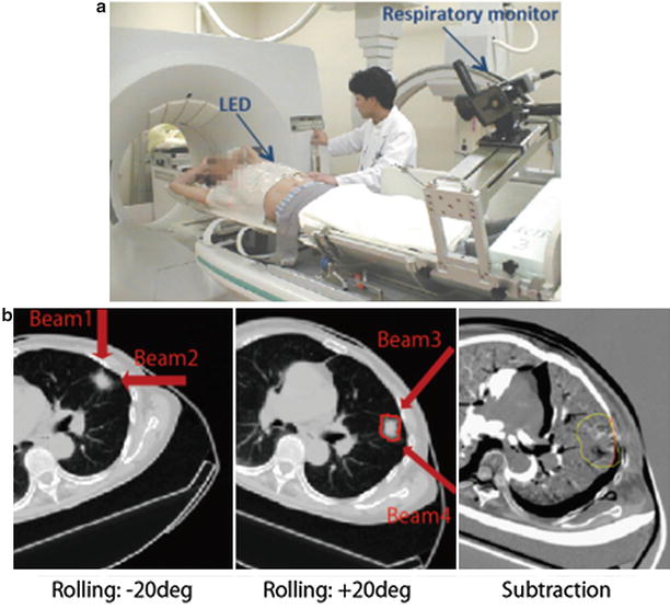
Fig. 9.4
(a) Respiratory correlated CT scan. (b) Left and middle panels: Axial CT images with the rotation of +20°/−20°. Right panel: Subtracted image using left and middle panels by registered by tumor position
Routine with our lung treatment protocol, the prescribed dose is administered to the target via four different beam angles from the isolateral rather than the contralateral side of the tumor using orthogonal beam ports by rotating the treatment couch in ±20° (left and middle panels in Fig. 9.4b). Immobilization devices could minimize patient positional errors, albeit that, patient positions in +20° rotation and in −20° rotation were not same (right panel in Fig. 9.4b). Therefore, treatment planning was performed using two CT data sets, respectively; beam numbers 1/2 and 3/4 were using −20° and +20° rotation, respectively.
Related posts:
Stay updated, free articles. Join our Telegram channel

Full access? Get Clinical Tree


