Over the past few decades, spinal magnetic resonance imaging (MR imaging) has largely replaced computed tomography (CT) and CT myelography in the assessment of intraspinal pathology at institutions where MR imaging is available. Given its high contrast resolution, MR imaging allows the differentiation of the several adjacent structures comprising the spine. This article illustrates normal spinal anatomy as defined by MR imaging, describes commonly used spinal MR imaging protocols, and discusses associated common artifacts.
Over the past few decades, spinal magnetic resonance imaging (MR imaging) has largely replaced computed tomography (CT) and CT myelography in the assessment of intraspinal pathology at institutions where MR imaging is available. Given its high contrast resolution, MR imaging allows the differentiation of the several adjacent structures comprising the spine. This article illustrates normal spinal anatomy as defined by MR imaging, describes commonly used spinal MR imaging protocols ( Tables 1–3 ), and discusses associated common artifacts.
| Sequence | Localizer | FLAIR | T2 | T2 | GRE | T1 | T1 | STIR | Enhanced T1 | Enhanced T1 |
|---|---|---|---|---|---|---|---|---|---|---|
| Plane | 3 plane | Sagittal | Sagittal | Axial | Axial | Sagittal | Axial | Sagittal | Sagittal | Axial |
| Coil type | Neck | Neck | Neck | Neck | Neck | Neck | Neck | Neck | Neck | Neck |
| Thickness, mm | 10 | 3 | 3 | 3 | 3 | 3 | 3 | 3 | 3 | 3 |
| TR, ms | 24 | 1700 | 3530 | 4210 | 32 | 653 | 649 | 4400 | 653 | 649 |
| TE, ms | 6 | 12 | 106 | 111 | 14 | 10 | 11 | 74 | 10 | 11 |
| Flip angle | 30 | 150 | 180 | 150 | 5 | 170 | 150 | 150 | 170 | 150 |
| NEX | 1 | 1 | 2 | 2 | 1 | 2 | 2 | 1 | 2 | 2 |
| Matrix | 128 × 256 | 250 × 384 | 269 × 384 | 240 × 320 | 216 × 320 | 269 × 384 | 205 × 256 | 192 × 256 | 269 × 384 | 205 × 256 |
| FOV read, mm | 300 | 260 | 240 | 200 | 200 | 240 | 240 | 240 | 240 | 240 |
| FOV phase, mm | 100 | 100 | 100 | 75 | 75 | 200 | 100 | 100 | 100 | 100 |
| Comments | Trauma, Mets | If indicated | If indicated | |||||||
| Sequence | Localizer | T1 | T2 | T2 | STIR | Enhanced T1 | Enhanced T1 |
|---|---|---|---|---|---|---|---|
| Plane | 3 plane | Sagittal | Sagittal | Axial | Sagittal | Sagittal | Axial |
| Coil type | Spine | Spine | Spine | Spine | Spine | Spine | Spine |
| Thickness | 10 | 4 | 4 | 4 | 4 | 4 | |
| TR, ms | 20 | 641 | 3000 | 7360 | 3220 | 670 | 579 |
| TE, ms | 6 | 17 | 100 | 106 | 74 | 14 | 13 |
| Flip angle | 30 | 180 | 150 | 150 | 180 | 150 | 130 |
| NEX | 1 | 1 | 2 | 1 | 2 | 2 | 2 |
| Matrix | 128 × 256 | 256 × 256 | 307 × 384 | 192 × 256 | 256 × 256 | 269 × 384 | 230 × 256 |
| FOV read, mm | 380 | 300 | 320 | 200 | 320 | 320 | 200 |
| FOV phase, mm | 100 | 100 | 100 | 100 | 100 | 100 | 100 |
| Comments | Trauma, Mets | If indicated | If indicated | ||||
| Sequence | Localizer | T1 FLAIR | T2 | T2 | T1 | STIR | Enhanced T1 | Enhanced T1 |
|---|---|---|---|---|---|---|---|---|
| Plane | 3 plane | Sagittal | Sagittal | Axial | Axial | Sagittal | Sagittal | Axial |
| Coil type | Spine | Spine | Spine | Spine | Spine | Spine | Spine | Spine |
| Thickness | 10 | 4 | 4 | 4 | 4 | 4 | 4 | 4 |
| TR, ms | 3.27 | 1600 | 3150 | 4250 | 500 | 4560 | 657 | 539 |
| TE, ms | 1.64 | 12 | 95 | 106 | 14 | 79 | 12 | 14 |
| Flip angle | 55 | 150 | 180 | 150 | 90 | 180 | 90 | 90 |
| NEX | 2 | 1 | 2 | 1 | 1 | 2 | 2 | 1 |
| Matrix | 115 × 256 | 256 × 256 | 256 × 256 | 218 × 256 | 205 × 256 | 192 × 256 | 192 × 256 | 192 × 256 |
| FOV read, mm | 450 | 280 | 280 | 200 | 200 | 280 | 280 | 200 |
| FOV phase, mm | 100 | 100 | 100 | 100 | 100 | 100 | 75 | 100 |
| Comments | Trauma, Mets | If indicated | If indicated | |||||
Spinal MR imaging techniques
Sagittal and axial magnetic resonance images should be acquired through the cervical, thoracic, and lumbar segments of the spine, as they are generally considered complementary, and imaging the spine in only one plane may result in misinterpretation. The addition of coronal images may also be useful, especially in patients with scoliosis. Stacked axial images and/or angled images through the discs can be obtained, often useful when the indication for imaging is pain, degenerative change, and/or radiculopathy. Although imaging in the axial plane is a matter of personal preference, using only angled axial images through the discs may be inadequate, as portions of the spinal canal will not be imaged axially. Slice thickness from 3 to 4 mm is generally optimal for imaging of the spine. Axial gradient-echo images through the cervical spine are typically 2 mm thick.
To depict the fine anatomic detail in the spine, high spatial resolution is a priority because of the small size of the cervical spine relative to the human body and because of the relatively superficial position of the spine within the human body. The use of surface coils, typically phased array receiver coils, helps to maximize signal-to-noise ratio and spatial resolution. Increasing phase-encoding steps results in a larger matrix and higher spatial resolution as a result but also leads to increased imaging acquisition time, which increases the possibility of motion-related image degradation. Among the other factors affecting spinal imaging are matrix size, field of view, gradient moment nulling motion compensation, pulse triggering and gating, band width, and phase-encoding axis.
The pulse sequences used are determined by the clinical indications for the examination based on the following major categories: degenerative disease including radicular symptomatology, trauma, cord compression/bony metastases, and infection. Spin-echo and fast spin-echo sequences are the most common sequences used in spinal MR imaging. Short tau inversion recovery (STIR) imaging is useful to assess the bone marrow and in cases of infectious, inflammatory, and neoplastic lesions. STIR imaging is also useful in the workup of trauma, to assess for ligamentous injury and changes from hemorrhage and/or edema. Contrast-enhanced imaging should be used, unless contraindicated, for indications including evaluation of the postoperative spine, suspected infection, or intradural or nontraumatic cord lesions. Abnormalities within the epidural space identified during unenhanced evaluation for metastases and/or cord compression can be better delineated using contrast-enhanced images.
Gradient-recalled echo (GRE), or gradient-echo, sequences allow for delineation of bone and disk margins, provide excellent contrast between the spinal cord and surrounding subarachnoid space, and allow clear visualization of the neural foramina and exiting nerve roots. Gradient-echo axial images are used in the cervical and thoracic spine to detect spinal canal and foraminal stenoses and serve as an important complement to long repetition time spin-echo imaging, given faster acquisition time of GRE. As a result, GRE images are less susceptible to patient motion artifact. Although signal-to-noise ratio is increased with GRE, fat is of low signal intensity on GRE sequences compared with T1-weighted spin-echo imaging; as a result, morphologic detail defined by fat is not as well demonstrated on GRE images as on spin-echo images.
Proton density images can be obtained simultaneously (TR 2000 to 3000 milliseconds or greater, TE 20 to 90 milliseconds) when obtaining T1-weighted images and can also be derived from an earlier (first) echo while generating T2-weighted images. Proton density images of the spine are not routinely obtained but can provide valuable information concerning normal and pathologic spinal morphology.
Normal spinal anatomy basics
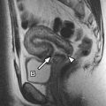
The cervical spine comprises the first 7 superior vertebrae of the spinal column. The first and second segments of the cervical spine are unique. The other cervical vertebrae are similar in size and configuration. The first segment, C1, also known as the atlas, is ring shaped and composed of anterior and posterior arches and lateral articular masses. It lacks a central vertebral body. The second segment, C2, also known as the axis, is also ring shaped and has a superiorly oriented odontoid process, also known as the dens, which lies posterior to the anterior arch of C1. The normal distance between the dens and anterior arch of C1 is approximately 3 mm in adults and 4 mm in children. There are prominent tubercles along the medial aspects of the lateral masses of C1 from which extend the transverse portion of the cruciate/cruciform ligament, ie, the transverse ligament, which confines the odontoid process of C2 posteriorly and delineates the anterior and posterior compartments. This relationship allows free rotation of C1 on C2 and provides for stability during upper cervical spinal flexion, extension, and lateral bending. The transverse ligament is covered posteriorly by the tectorial membrane. The alar ligaments are paired winglike structures connecting the lateral aspects of the odontoid process with the occipital condyles. The thin apical ligament of the odontoid process directly anchors the tip of the odontoid process to the clivus in the anterior aspect of the foramen magnum. The tip of the odontoid process is anterior to the lower medulla. A line of low T1-weighted signal intensity seen through the base of the dens represents the subdental synchondrosis, present in many healthy individuals; it may be distinguished from a fracture because the synchondrosis does not extend to the adjacent cortical bone ( Figs. 1 and 2 ).


Unique to the cervical spine, the bilateral uncovertebral joints, also referred to as Luschka joints, are formed by articulation of the uncinate process of the inferior vertebral body with the uncus of the superior vertebral body (see Fig. 2 ; Figs. 3 and 4 ). The uncus is a cup-shaped groove on the posterior/inferior aspect of each cervical vertebral body (except C1), whereas the uncinate processes are located bilaterally on the posterosuperior aspects of the cervical vertebral bodies (except for C1 and C2). The cervical vertebrae also form transverse foramina bilaterally through which the vertebral arteries pass. Although the C7 vertebral body forms transverse foramina, the vertebral arteries usually enter the foramina at C6. The vertebral arteries are seen as circular low-signal structures owing to the flow-void phenomenon (see Fig. 3 B). The spinous processes of the cervical spine are short and have bifid tips. Compared with the lumbar disks, the disks of the cervical and thoracic spine are much thinner and the outermost portion of the anulus is not as thick. The cervical spine is depicted in images in Figs. 1–5 and Fig. 6 .