A. Stable nuclei
–Atomic nuclei contain protons and neutrons (i.e., nucleons).
–Nucleons are held together by the strong force.
–Energy required to remove a nucleon from a nucleus is nucleon binding energy.
–Nuclide mass number A is the sum of the number of protons (Z) and neutrons (N).
–For each nuclide, A = Z + N.
–Stable 127I has 127 nucleons (Z = 53 and N = 74).
–Nuclides having the same mass number A are called isobars.
–Nuclides having the same atomic number (protons) are called isotopes.
–Table 9.1 lists the three isotopes of hydrogen.
–Nuclides having the same number of neutrons are called isotones.
–An isomer is the excited state of a nucleus.
–Stable low mass number nuclides have approximately equal numbers of neutrons (N) and protons (Z).
–The most common carbon nucleus (12C) has six protons and six neutrons, and the most common oxygen nucleus (16O) has eight protons and eight neutrons.
–Stable high mass number nuclides have more neutrons than protons.
–The most common tungsten nucleus (184W) has 74 protons and 110 neutrons.
–Figure 9.1 graphically shows the number of neutrons and protons in stable nuclei found in nature.
B. Unstable nuclei
–Unstable nuclides are called radionuclides.
–Very heavy nuclei (Z > 82) tend to be unstable.
–The transformation of an unstable nuclide is called radioactive decay.
–The original nuclide is the parent, and the nuclides resulting from the nuclear transformation are daughters.
–Unstable nuclides undergo nuclear transformation as summarized in Table 9.2.
–In all nuclear transformations, the total energy is always conserved.
–Mass number and electric charge are also conserved when nuclei decay.
–The ground state is the lowest energy state of a nucleus.
–Nuclear ground states are the most stable arrangement of nucleons.
–Higher energy levels (excited states) are known as isomeric states.
–Isomeric states are always unstable.
–Excited states will transform into a lower energy level, emitting a gamma ray or internal conversion electron.
–A gamma ray is electromagnetic radiation originating in a nuclear transformation.
–The excess energy may be transferred to an orbital electron, which is then emitted from the atom as an internal conversion electron.
–After an isomeric transition, both parent and daughter nuclei have the same mass number and atomic number.
–Isomeric states that have long lifetimes are called metastable.
–To be called metastable, the half-life must be longer than 10−9 second.
–The metastable state of an atom is denoted by a lower case m following the mass number (e.g., 99mTc).
TABLE 9.1 Isotopes of Hydrogen

C. Alpha decay
–In alpha decay, a radionuclide emits an alpha particle consisting of two neutrons and two protons.
–An alpha particle is the nucleus of a helium atom.
–Alpha decay is most common in atoms with a high atomic number (Z>82).
–226Ra is a common alpha emitter found in nature.
–226Ra decays to 222Rn (radon), which is another alpha emitter.
–In alpha decay, the atomic number decreases by two and the mass number decreases by four.
–Energies of alpha particles are generally between 4 and 7 MeV.
–Alpha particle energies are discrete and well defined for a given alpha emitter.
–Alpha particles travel <0.1 mm in tissue, losing their energy by ionizing atoms along the track length.
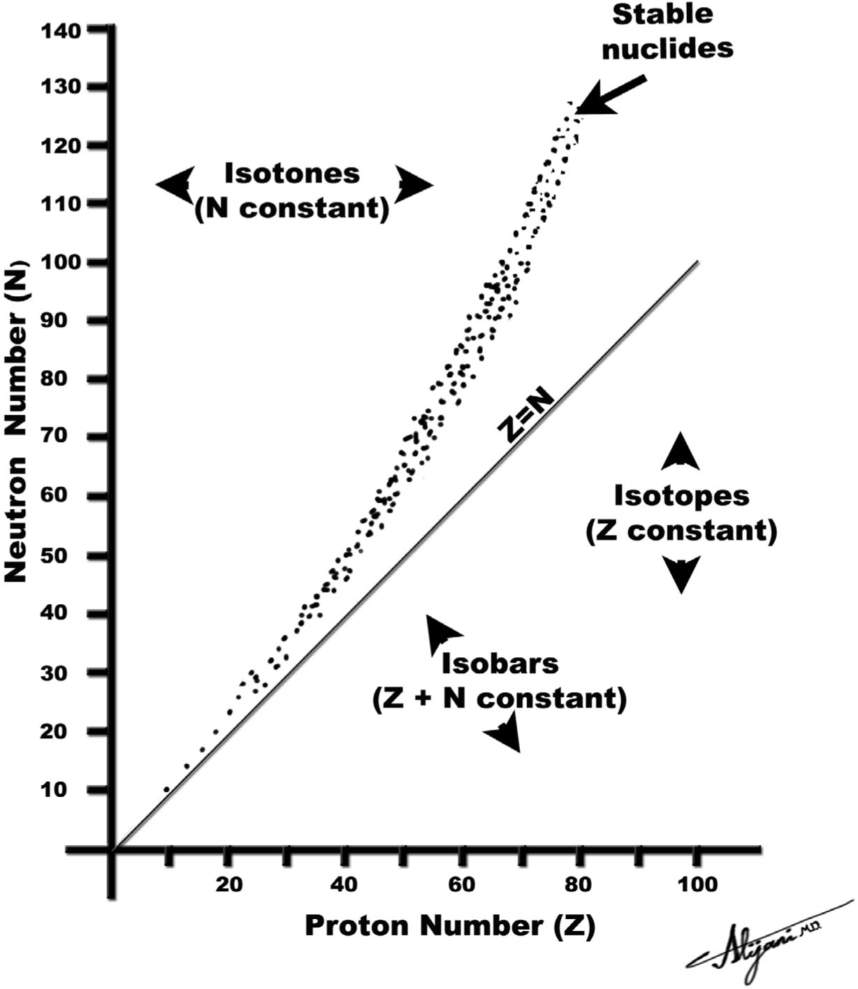
FIGURE 9.1 Each dot represents a stable nucleus found in nature.
TABLE 9.2 Radioactive Decay Modes for Unstable Nuclei Containing Protons (Z), Neutrons (N), and mass number A = Z +N

–Alpha particles pose little risk as an external radiation source as they cannot penetrate through the skin.
–Alpha particles may pose a high risk if ingested, inhaled, or injected.
–Radioactive radon (plus daughters) is hazardous because radioactivity is deposited in the lung, with a subsequent risk of lung cancer (Chapter 8, Section VI).
D. Beta minus decay
–In beta minus (β−) decay, a neutron inside the nucleus is converted into a proton.
–Beta minus decay occurs in nuclei with an excess of neutrons (i.e., too few protons).
–The excess energy is released as an energetic electron, called a beta particle.
–Beta minus decay also results in the emission of an antineutrino.
–Antineutrinos have no rest mass or electric charge and rarely interact with matter.
–In beta minus decay, the atomic number increases by one, but the mass number remains constant.
–Beta particles (electrons) emitted during beta minus decay have a range of energies up to a maximum energy.
–Plotting the number of electrons at each energy against the energy shows the electron spectrum.
–The maximum energy in this spectrum is denoted Emax.
–The average energy of beta emitters is approximately one third the maximum.
–Average beta particle energy is ~Emax/3.
–The energy difference between Emax and any given beta particle energy is carried away by the antineutrino.
–32P is a pure beta emitter with maximum beta particle energy of 1.71 MeV.
–The mean beta particle energy of 32P is ~0.570 MeV.
–3H (tritium) (Emax = 18 keV) and 14C (Emax = 156 keV) are low energy β− emitters that are ubiquitous in biomedical research.
–Figure 9.2A shows the beta minus decay of tritium.
E. Beta plus decay
–In beta plus (β+) decay, a proton inside the nucleus is converted into a neutron.
–The excess energy is emitted as a positively charged electron called a positron.
–Positrons have the same properties as electrons, except that their charge is positive (electrons have negative charges).
–Beta plus decay (positron emission) occurs in neutron-deficient nuclei (i.e., too many protons).
–Beta plus decay also results in the emission of a neutrino.
–A neutrino has no electric charge or rest mass and is similar to an antineutrino.
–Beta plus decay is also known as positron emission.
–In beta plus decay, the atomic number decreases by one and the mass number stays the same.
–Energetic positrons lose their energy by ionization and excitation of atomic electrons.
–When the positron loses all of its kinetic energy, it annihilates with an electron.
–The mass of the positron and electron (511 keV each) are converted into two 511-keV photons that are emitted in opposite directions (i.e., 180 degrees apart).
–Many common positron emitters have very short half-lives.
–11C half-life is 20 minutes (Fig. 9.2B), and 15O half-life is 2 minutes.
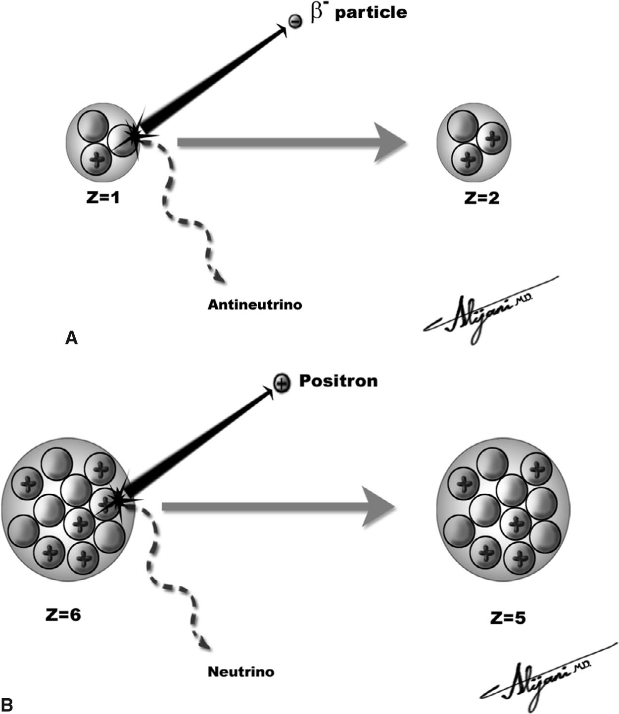
FIGURE 9.2 Beta decay. A: Beta minus decay of tritium (left), which decays by emitting an electron (i.e., beta minus particle) and an antineutrino and is thereby transformed into 3He (right); B: Beta plus (positron emitter) of 11C (left), which decays by emitting a positron and neutrino and is thereby transformed to 11Boron (right).
–The most popular positron emitter used in nuclear medicine is 18F with a half-life of 110 minutes.
–The maximum energy of the 18F positron is 0.63 MeV, and the average positron energy is one third the maximum (i.e., 0.21 MeV).
–The distance (range) that the average 18F positron travels in soft tissue is ~0.4 mm.
–Positron ranges will increase in lower density tissues (e.g., lung).
F. Electron capture
–In electron capture, a proton inside the nucleus is converted into a neutron by capturing an atomic electron.
–The electron that is captured most likely originates in the K-shell.
–A neutrino is emitted during electron capture.
–Electron capture occurs in nuclei deficient in neutrons (too many protons).
–In electron capture, the atomic number decreases by one and the mass number stays the same.
–If the captured electron is from the K-shell, the resultant K-shell vacancy is filled by an outer shell electron.
–The excess energy is emitted either as a characteristic x-ray or Auger electron (see Chapter 1).
–Electron capture may compete with beta plus decay.
–Important electron capture radionuclides used in nuclear medicine are 67Ga, 111In, 123I, and 201Tl.
–57Co is also an electron capture radionuclide used for quality control of scintillation camera uniformity.
A. Production of radioactivity
–Radionuclides may be produced in a nuclear reactor by adding neutrons to a stable nuclide.
–59Co + neutron → 60Co, which is called neutron activation.
–Neutron activation products cannot be chemically separated.
–Reactor-produced radionuclides generally decay by a beta minus process.
–Radionuclides may be produced in cyclotrons where charged particles (e.g., protons or deuterons) are added to stable nuclides.
–201Hg + deuteron → 201Tl + two neutrons.
–Cyclotron-produced radionuclides can decay by a beta plus process.
–15O is produced in a cyclotron and is a positron emitter.
–Cyclotron-produced radionuclides may also decay by electron capture.
–123I is produced in cyclotrons and decays via electron capture.
–Radionuclides may also be produced as fission products when heavy nuclides break up.
–In nuclear medicine, generators are used to produce radionuclides that are short lived.
–In a generator, the useful radionuclide (daughter) is continuously produced by the radioactive decay of a longer-lived (parent) radionuclide.
–In generators, the parent half-life is longer than that of the daughter.
–Technetium-99m and rubidium-82 are obtained from NM generators.
–99mTc is obtained from 99Mo and emits gamma rays (isomeric transition), and 82Rb is obtained from 82Sr and is a positron emitter.
–Table 9.3 lists the modes of production, as well as key characteristics, of common radionuclides used in nuclear medicine.
B. Measuring radioactivity
–Activity is the number of transformations per unit time.
–The SI unit of activity is the becquerel (Bq).
–One becquerel is one transformation per second.
–The non-SI unit is the curie (Ci).
–One curie is 3.7 × 10¹⁰ transformations per second.
–An activity of 1 mCi is equivalent to 37 MBq.
–Physical half-life (T1/2) is the time required for a half of the radionuclide present to decay.
–The fractional activity remaining after n half-lives is 1/2n (Fig. 9.3).
–After ten half-lives, only 0.1% of the initial activity remains (1/210 is ~1/1,000).
–Radioactivity decays exponentially and is characterized by the decay constant λ.
–Activity is N × λ, where N is the number of atoms in the sample.
–The fractional activity of a source remaining at time t is e−λ×t.
–The relationship between λ and half life T1/2 is given by T1/2 = 0.693/λ.
TABLE 9.3 Characteristics of Common Radionuclides
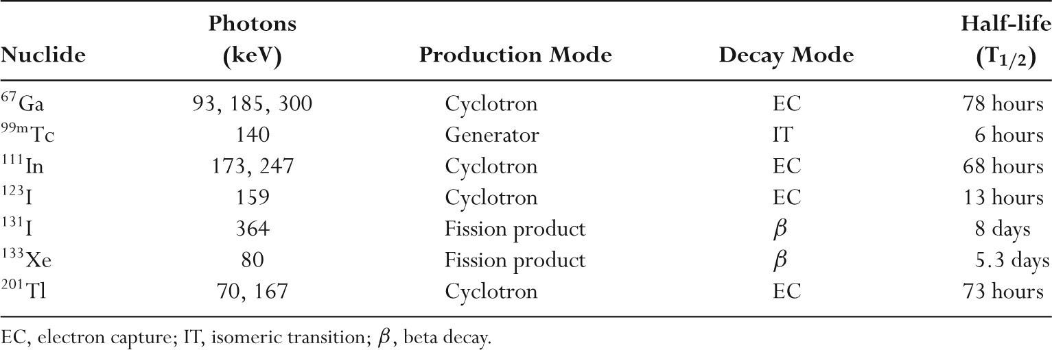
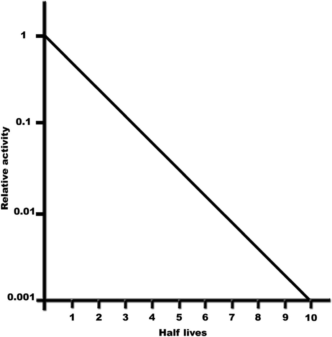
FIGURE 9.3 Plot of relative activity as a function of half-life (time), showing that the remaining activity after ten half-lives is only 0.1% of the initial activity.
C. 99Mo/99mTc generators
–Technetium (99mTc) is readily available from a generator used in ~80% of all nuclear medicine examinations.
–99mTc has a gamma ray energy of 140 keV that is ideal for imaging and a half-life of 6 hours that is convenient.
–Pertechnetate (99mTcO4) is produced directly from 99Mo using a saline eluant.
–The technetium generator is shielded with lead and consists of an alumina column loaded with 99Mo.
–99Mo decays to 99mTc, and saline is added to the generator when 99mTc is needed.
–Saline passes through the column to elute (wash off) the 99mTc in the form of sodium pertechnetate.
–The 99Mo is not soluble in saline and remains in the column.
–99mTc decays by isomeric transition where 88% of nuclear transformations result in emission of a 140-keV gamma ray.
–Energy is also emitted in the form of internal conversion electrons, characteristic x-rays, and Auger electrons.
–The half-life of 99Mo is 66 hours, which allows the generator to remain useful for approximately 1 week (~2.5 half-lives).
–A99mTc generator is normally eluted daily over the course of a week (Fig. 9.4) and then replaced.
D. Generator equilibrium
–A brand new 99Mo/99mTc generator has only 99Mo activity but no 99mTc activity.
–A typical generator initially starts with ~37 GBq (1 Ci) of 99Mo.
–As 99Mo decays, 99mTc activity is produced.
–The daughter (99mTc) activity increases until equilibrium is reached.
–For practical purposes, at equilibrium the activities of parent and daughter may be taken to be approximately equal.
–In equilibrium, a 1 Ci 99Mo generator also has approximately 1 Ci of 99mTc.
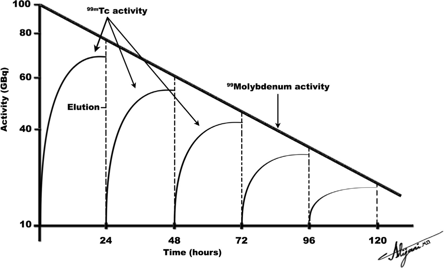
FIGURE 9.4 Idealized plot of parent 99Mo and daughter 99mTc activities as a function of time, where the 99Mo/99mTc generator is eluted at intervals of 24 hours.
–It takes approximately four daughter half-lives to reach equilibrium.
–A 99Mo generator thus takes approximately 24 hours to reach equilibrium.
–Figure 9.4 shows an idealized schematic of the activity of the parent 99Mo and the daughter 99mTc.
–In equilibrium, the activity of 99mTc is ~90% of the 99Mo activity.
–Transient equilibrium is the name given when the parent radionuclide is short lived.
–Secular equilibrium is the name given when the parent is long lived.
–The essential physics of secular and transient equilibrium are identical.
–Both secular and transient equilibrium occur after four daughter half-lives with both parent and daughter activities being approximately equal.
E. Radiopharmaceuticals
–Radionuclides should have a short half-life to minimize the patient radiation dose.
–Ideal gamma rays have energies between 100 and 300 keV.
–The gamma ray must have enough energy to get out of the patient, but not so high that it is difficult to detect.
–Radionuclides should have minimal particulate radiations (e.g., beta particles) to minimize patient dose.
–Evaluation of function, not anatomy, sets nuclear medicine studies apart.
–Radiopharmaceuticals are designed to mimic a natural physiologic process.
–The design of a radiopharmaceutical should ensure that it will localize in the organ or tissue of interest.
–Important characteristics of radiopharmaceuticals are that they be nontoxic, and contain no contaminants.
–Contaminants of radiopharmaceuticals include chemicals and radionuclides.
–There are a number of radiopharmaceutical localization mechanisms.
–Active transport such as thyroid uptake scanning with iodine.
–Compartmental localization such as blood pool scanning with human serum albumin, plasma, or red blood cells.
–Simple exchange or diffusion such as bone scanning with pyrophosphates.
–Phagocytosis such as liver, spleen, and bone marrow scanning with radiocolloids.
–Capillary blockade such as lung scanning with macroaggregate (8–75 μm) or organ perfusion studies with intra-arterial injection of macroaggregates.
–Cell sequestration such as spleen scanning with damaged red blood cells.
A. Scintillation cameras
–Scintillation cameras produce projection images of the distribution of radioactivity in patients.
–Figure 9.5 shows a schematic view of a scintillation camera.
–Scintillation cameras are sometimes called gamma cameras or Anger cameras.
–Scintillation rays emerging from the patient pass through a lead collimator that only allows photons traveling parallel to the collimator holes to reach the scintillator.
–Collimators are essential for providing spatial information in planar NM imaging.
–Gamma rays that pass through the collimator are incident on a NaI scintillator.
–Scintillators absorb incident gamma photons and produce many light photons.
–Approximately 10% of the absorbed gamma ray energy is converted to light.
–Light output from the NaI scintillator is detected by an array of photomultiplier tubes (PMTs) and converted to an electrical signal.
–Scintillation cameras typically use 55 PMTs.
–The position of the gamma ray interaction is determined by a pulse arithmetic circuit based on the relative strength of signals from each PMT.
–Count refers to the registration of a single gamma ray by the detector, and ~500,000 counts are acquired for a typical scintillation camera image.
–Scintillation cameras use computers to store, manipulate, and display the acquired image data.
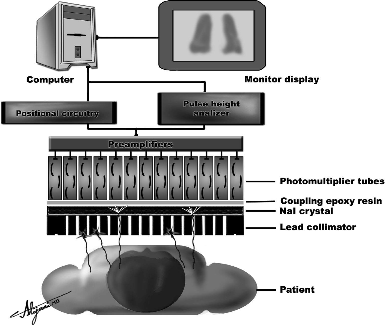
FIGURE 9.5 Schematic of a scintillating camera showing the key components of a collimator which include the NaI detector, an array of light detectors (i.e., photomultiplier tube), and light analysis circuits (i.e., PHA + positional circuitry).
–Scintillation cameras have corrections made to the acquired image data that correct for system spatial nonlinearity and nonuniformities.
–Energy corrections are also incorporated to account for differences in the response of individual photomultiplier tubes.
–Scintillation cameras have lead shielding to prevent unwanted background radiation from the room or other areas of the patient from contributing to the image information.
B. Collimators
–Collimators are typically made of lead and contain multiple holes (Fig. 9.5).
–The lead strips between the holes are called septa.
–Parallel-hole collimators project the same object size onto the camera, and the field of view (FOV) does not change with distance.
–Converging collimators produce a magnified image, and FOV decreases with distance.
–Diverging collimators project an image size that is smaller than the object size, and FOV increases with distance.
–Pinhole collimators are cone shaped with a single hole at the apex.
–Images generated using a pinhole collimator are normally magnified and inverted.
–Figure 9.6 shows a pinhole collimator used to obtain magnified images of the thyroid.
–Collimator sensitivity is the fraction of gamma rays reaching it from all directions that pass through the holes.
–Collimator sensitivity is low with approximately 10−4, or only 0.01%, of the emitted photons being detected.
–High-sensitivity collimators have larger holes and lower resolution.
–High-resolution collimators have smaller holes and lower sensitivity.
–Table 9.4 summarizes the collimator resolution performance.
–Resolution is degraded with increasing distance from the collimator.
–Low-energy collimators used with 99mTc and 201TI have thin septa.
–Low-energy high-resolution (LEHR) collimators are most frequently used.
–Medium-energy collimators used with 67Ga and 111In have thicker septa and therefore fewer holes and lower sensitivity.
–High-energy collimators are required for 131I imaging and have the thickest septa.
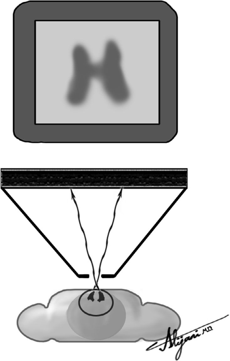
FIGURE 9.6 Pinhole collimator used to generate thyroid images.
TABLE 9.4 Representative FullWidth Half Maximum (FWHM) Resolution

C. NaI crystal
–NaI scintillators detect gamma rays emerging from patients and are generally rectangular.
–NaI crystals are very fragile and easily damaged.
–For gamma ray imaging, NaI scintillators are ~10 mm thick.
–As scintillator thickness increases, sensitivity improves but resolution gets worse.
–A photopeak is when an incident gamma ray is completely absorbed (photoelectric effect).
–The detection efficiency is the percentage of incident gamma rays absorbed in the scintillator.
–Table 9.5 shows how NaI detection efficiency varies with photon energy.
–Increasing the photon energy from 100 to 500 keV reduces detection efficiency from 100% to 6%.
–An iodine escape peak occurs at approximately 30 keV below the photopeak and is the result of characteristic K-shell x-rays from iodine that escape the crystal.
–Scatter events
Stay updated, free articles. Join our Telegram channel

Full access? Get Clinical Tree


