Abstract
The technology boom in computed tomography technology has resulted in an exponential increase in its use and application in modern medicine. This has led to an overall increase in radiation dose contributions from computed tomography scanning and consequent concerns over potential risks of radiation-induced carcinogenesis. In addition to notable advances in speed, resolution, and coverage of multidetector row computed tomography scanners, vendors have also introduced a number of technologies to help make the computed tomography scanners more dose efficient and reduce associated radiation dose from scanning. These include efficient detectors, automatic exposure control, automatic tube potential selection, beam-shaping filters, and iterative image reconstruction techniques. Several studies have outlined strategies for radiation dose reduction based on patient size, the body region being imaged, and clinical indications for radiation dose reduction. In this chapter, we discuss techniques and strategies for radiation dose optimization in computed tomography while maintaining diagnostic image quality.
Keywords
CT, dose reduction techniques, radiation dose, radiation protection, radiation safety
Evolution of Computed Tomography Technology
Computed tomography (CT) plays a major role in the practice of medicine. CT was invented by the British scientist Sir Godfrey Hounsfield in 1972 at Electric and Musical Industries research laboratories. Since its invention, CT has evolved rapidly and transformed the field of medicine. The first CT scanners were dedicated to acquiring head images. With development of subsequent scanners, it became possible to acquire images of other parts of the body. The first-generation scanners were axial (or step and shoot) CT scanners with a pencil x-ray beam (with a single or double row of detectors). These early axial CT scanners required around 5 minutes for acquisition of a single slice with reconstruction time of about 1.5 minutes per slice.
The second-generation axial CT, with a fan x-ray beam, took around 20 seconds for acquisition of a single slice. The first- and second-generation CT scanners used complex translation and rotation motion of the x-ray tube and detector elements for acquisition of images, which limited their scanning speed. Subsequent research in CT technology led to development of the fourth-generation axial CT (with a wider fan x-ray beam) in the early to mid-1970s. For axial scanning, the x-ray tube revolves 360 degrees around the patient in one direction to acquire a single slice, then the gantry table moves forward and the x-ray tube revolves 360 degrees around the patient in the opposite direction to acquire a second slice.
There were several limitations of the first- and second-generation axial CT scanners, including long scan times, inability to generate volumetric datasets, and inferior spatial and temporal resolution. In 1989, invention of slip-ring technology allowed continuous gantry (x-ray tube and detector array) rotation while the gantry table moved through the rotating gantry for acquisition of volumetric data. This slip-ring technology gave birth to continuous spiral or helical CT scanning, which helped overcome several limitations of axial CT. Helical CT scanning revolutionized the field of CT. With helical scanning, the entire chest or abdomen could be scanned within 20 to 30 seconds. Also, volumetric data acquisitions in helical scanning enabled generation of three-dimensional images for visualization of complex anatomic structures such as the heart, blood vessels, and fractures.
The first helical CT scanners were single-detector-row CT (SDCT) scanners in which a single detector row was placed along the patient’s length or z -axis. Due to limitations of the single detector row along the z -axis, SDCT scanners were not able to efficiently use the entire fan x-ray beam. Spatial (slice thickness about 1 mm) and temporal (speed) resolution of SDCT were also limited. With the advancement of CT technology, multidetector row CT (MDCT) scanners were introduced to maximize the use of the fan x-ray beam. In 1992, the first MDCT scanners with dual-slice capabilities (with two detector rows) were introduced. Four-slice MDCT scanners were introduced in 1997, 64-slice scanners in 2004, and 320-slice scanners in 2007.
Due to an increase in the number of detector rows along the z -axis, a wider area (up to 16 cm) can be scanned in a single rotation within a fraction of a second. Modern MDCT scanners can complete a single x-ray tube revolution in as little as 0.25 seconds. Use of thinner detector elements led to improvement in the spatial resolution of MDCT, which can now generate a slice thickness of 0.5 mm through the entire volume of a scanned body region. The current MDCT scanners are also extremely dose efficient and capable of using up to 98% of the x-ray beam per rotation to generate CT images. The latter has enabled a substantial radiation dose reduction in recent years. Not unintentionally, advancements in MDCT capabilities have been associated with development of dose reduction technologies such as automatic exposure control (AEC), automatic kilovoltage selection, prepatient beam collimation, and iterative reconstruction techniques (IRTs).
With changes in CT technologies, substantial growth in the use of CT was reported. For each individual in the United States, the annual effective dose from medical imaging (mostly from CT) increased from 3.6 mSv in 1980 to 6.2 mSv in 2006. The increased radiation dose contribution from medical imaging was accompanied by evidence of large variations in scanning preferences and radiation doses for the same body regions in similarly sized patients across different hospitals in the United States. CT radiation dose optimization is vital to ensure that the radiation dose to each patient is as low as reasonably achievable (ALARA). This chapter discusses how various CT protocols can be tailored for radiation dose optimization based on the appropriateness or clinical indication for the exam and the patient’s body region, age, and size.
Appropriateness of Computed Tomography
A major step in optimizing CT radiation dose is making sure that all CT exams are performed for appropriate clinical reasons. CT exams that are ordered based on clinical indication have a higher likelihood of providing information regarding a diagnosis (or disease process). However, if such information can be obtained from other low-radiation (plain radiograph) or nonradiation (ultrasound and magnetic resonance imaging [MRI]) imaging tests without compromising the clinical care of the patient, then CT should not be performed.
It is very important to avoid duplicate CT exams, which can substantially reduce radiation dose. The radiation dose information for all exams should be maintained and audited. There are various guideline resources and tools (websites, software) available for assessing the appropriateness of CT. Several clinical decision support (CDS) software systems are available to check the appropriateness of ordering CT. Overall, the appropriateness criteria for CT can avoid unnecessary CT exams and help reduce radiation dose imaging costs. Avoiding unnecessary exams can also reduce the anxiety among patients due to incidental findings of uncertain significance and avoid adverse effects due to contrast media.
Guidelines for use of CT scanning have been developed by several organizations including the American College of Radiology (ACR) Appropriateness Criteria, the European Commission Referral Guidelines for Imaging, the Royal College of Radiologists radiological investigation guidelines tool, and the Royal College of Radiologists of Australia, and New Zealand Diagnostic Imaging Pathways. Many other institutions and private organizations have also provided guidelines for appropriateness of CT and other imaging tests. The ACR Appropriateness Criteria help ordering physicians to choose the best imaging test for a given clinical indication. It provides a rating on a scale of 1 to 9 (where score 1 is the least useful imaging test and score 9 is most likely useful for a given clinical indication). It also provides the relative radiation level of an imaging test to help determine the benefit of the test (from the score) against its radiation level. The European Commission also provides comprehensive referral guidelines for physicians for imaging modalities. In the United Kingdom, the Royal College of Radiologists tool helps physicians determine the best available practices involving imaging tests for patient referral. In Australia, the Diagnostic Imaging Pathways tool provides guidelines for different organs or systems based on disorders and clinical features.
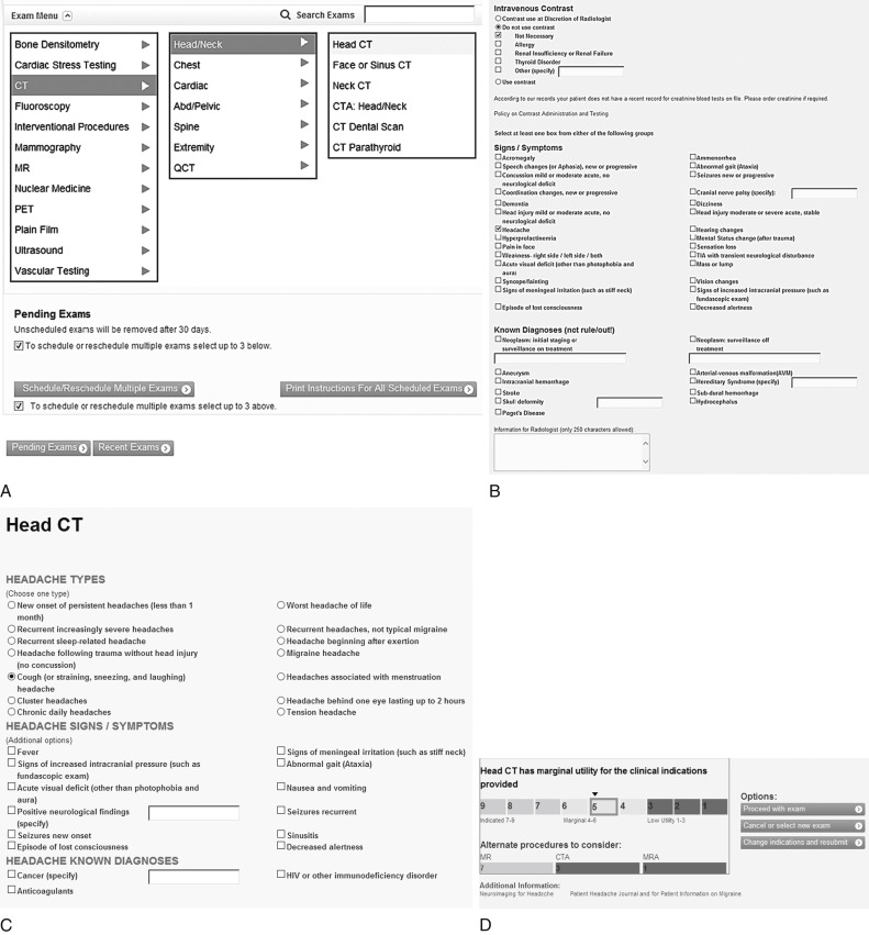
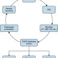
The various online software and CDS systems, such as radiology order entry, help physicians order imaging studies. Some decision support systems follow the ACR Appropriateness Criteria guidelines while others include input from the subspecialty physicians and radiologists. At Massachusetts General Hospital, the CDS system displays all available imaging studies (radiograph, ultrasound, CT, MRI, fluoroscopy, and nuclear medicine) to the ordering physician. In the system, the ordering physician logs in, enters the patient’s medical record number, and selects the particular imaging test (such as CT head) based on the patient’s clinical findings (such as headache, Fig. 23.1A ). The system then requests more specific information regarding the imaging test and signs and symptoms (type of headache, such as cough headache, and sinusitis, see Fig. 23.1B and C ). Based on the chosen imaging tests and clinical findings, the system provides scores from 1 to 3 (low utility), 4 to 6 (intermediate utility), and 7 to 9 (high utility) along with the expected usefulness in providing relevant information (see Fig. 23.1D ). The system provides alternate imaging studies with their utility scores so that if appropriate, the ordering physician can change and select an imaging test with a higher utility score (see Fig. 23.1D ). If two imaging tests (such as chest radiograph and CT) receive similar scores, the ordering physician can consider ordering an inexpensive exam or an exam with a lower radiation dose, such as a chest radiograph instead of a chest CT first, unless that test has already failed to clarify the clinical picture.
The system also alerts physicians and radiologists to the patient’s prior imaging studies to avoid ordering duplicate or redundant examinations. The systems also provide a radiation alert message if there are prior radiation-based tests for the patient. The radiation alert message informs the physician about the need to perform CT only when essential and limit the exposed area to the minimum required for diagnosis. When possible, outside imaging studies should be obtained if they can help avoid a new study.
Prior publications have reported the effect of implementation of appropriateness-based CDS systems. Sistrom et al. analyzed the effect of a CDS system (or radiology order entry) on the growth of outpatient imaging studies and reported a significant decrease in outpatient CT and ultrasound exams following implementation of the CDS. Raja et al. analyzed the effect of a CDS system on the use and yield of CT pulmonary angiography in the emergency department and reported a significant decrease in use and increase in yield of CT for assessment of acute pulmonary embolism. Dunne et al. reported similar findings in an inpatient population with use of a CDS system associated with decreased (12%) use of CT pulmonary angiography.
The Radiation Protection of Patients website of the International Atomic Energy Agency has outlined 10 guidelines related to appropriate referrals for CT:
- 1.
Avoid unnecessary imaging examinations.
- 2.
Discuss the choice of imaging test with radiologists to strengthen the justification process.
- 3.
Discuss the benefits and risks of the examinations with patients.
- 4.
Use appropriateness criteria and referral guidelines in daily practice.
- 5.
Consult the radiologist or medical physicist and seek information about guidelines for referring medical practitioners.
- 6.
Be careful to avoid inappropriate pediatric examinations because pediatric tissues are more sensitive to radiation, and they have a longer lifespan over which cancer effects may be expressed.
- 7.
The number of CT scans, especially in children, must be decreased to make use of CT safer.
- 8.
Before imaging tests, always ask if women of childbearing potential could be pregnant.
- 9.
If CT is not indicated, then discuss the reasons for not performing the examination with the patient if the patient asks.
- 10.
Always look for similar prior exams performed in patients to avoid needless repeat scanning.
Stratification of Computed Tomography Protocols
Body regions (head, chest, abdomen, etc.) are anatomically different, and therefore require different CT radiation doses. For all body regions, CT protocols should be named, dated, and archived on scanners. Modification or adjustment of protocols can be done at the time the CT exam is performed. However, spontaneous or on the fly creation of protocols is not optimal because valuable time can be wasted for urgent CT and not all operators have similar levels of training and understanding, which can result in errors. It is difficult to achieve consistency in protocols if they are created on the fly, which can make it harder to assess radiation doses for different clinical indications and patient sizes.
When creating scan protocols, one should make sure that all scan protocols have specific clinical indications for their use. First, body region–specific protocols should be created based on clinical indications. Each protocol (except for head CT) can be then subdivided based on patient size or weight, although with use of AEC techniques and automatic kilovoltage selection techniques, modern scanners can automatically optimize radiation dose and achieve a specified image quality according to body habitus determined from the planning radiographs. These automatic techniques need modifications for very small or very large body habitus and for different clinical indications. Next, each scan protocol must have specific guidelines on the number of scan phases, scan range for each phase, and scan parameters for each phase, based on patient size or weight. The following sections present key scanning aspects of CT protocols based on body region.
Head Computed Tomography
The head is one of the most frequently scanned body regions. Brain MRI has replaced head CT for several clinical indications, although the head CT is still used quite frequently for evaluation of trauma and stroke. When creating head CT protocols, users must take into account distinctive aspects of the head region. The skull base is the densest bone in the body and has a tendency to cause beam hardening artifacts on CT. Versus other body regions, the head anatomy changes rapidly from the skull base to the vault. Subtle differences between attenuation of gray and white matter in the brain lead to extremely low contrast in CT images, which may be adversely affected by the presence of high image noise on inadvertently low radiation dose images. Certain head CT exams for evaluation of paranasal sinuses, craniostenosis, and ventricular shunt patency can be performed at substantially reduced doses due to relatively high tissue contrast. Other head CT, such as for stroke and CT angiography of head and/or neck, require relatively higher doses. When appropriate and possible, brain MRI should be acquired.
Pediatric head CT should be acquired at a reduced radiation dose compared to adult head CT. When creating protocols, one should make sure that head CT doses are well under the recommended regional or national reference dose levels (RDLs). The ACR recommends an RDL of 75 mGy and an achievable dose level of 57 mGy for adult head CT (both values represent CT dose index volume [CTDIvol] using a 16-cm phantom size). The corresponding recommended levels for pediatric head CT examinations are 40 and 31 mGy, respectively. The RDL implies that 75% of the surveyed institutions use a radiation dose below the specified dose level, whereas achievable doses represent a dose limit for 50% of the surveyed institutions.
Routine Head Computed Tomography
Common indications for performing routine head CT include acute head trauma, suspected intracranial hemorrhage, and altered neurologic or mental status. Routine head CT can be performed with axial scanning mode (with gantry tilt) or helical scanning mode (without gantry tilt). Helical scanning is fast and can generate multiplanar images with diagnostic image quality at CTDIvol of 45 to 60 mGy. However, helical scanning can lead to higher eye dose. Some studies report that eye doses from helical CT are greater than tilted axial scanning of the head. A gantry tilt is also not possible with helical scanning. However, axial scanning is slow and has higher chances of motion artifacts. Many hospitals prefer axial scanning over helical CT, although at Massachusetts General Hospital, routine head CT is performed with the helical acquisition technique. Prior studies have suggested that image quality of narrow collimated helical CT is similar to that of wide collimated axial CT.
When using helical mode for head CT scanning, an overlapping pitch (∼0.5:1) should be used to decrease artifacts from rapidly changing anatomy, particularly at the skull base. Also, narrow beam collimation should be used to decrease the radiation dose from overranging at the beginning and end of the helical mode. Motion artifacts can be minimized with faster gantry rotation speed. For uncooperative patients, faster scanning is preferred. It is important to ensure that the head is well positioned and isocentered. Scan length should be targeted on the region of interest.
As stated earlier, routine head CT can be performed with fixed milliamperage or AEC techniques. Because brain parenchyma has lower inherent tissue contrast, a comparatively higher tube current is often needed for scanning. Prior studies have reported the potential for substantial dose reduction for head CT with fixed milliamperage and with AEC techniques. Application of IRTs decrease image noise and artifacts and allow scanning at lower tube current compared to the conventional filtered backprojection (FBP) method of image reconstruction.
Typically, routine adult head CT is performed at 120 kV. Only essential or minimum scan series should be acquired. Lower doses should be used for acquisition of localizer radiographs. Scanning of the same regions (head and temporal bone, face and sinuses) should be avoided. Extraneous hardware must be removed before scanning to avoid artifacts and improve image quality. For head CT, shielding can be used to reduce the dose to the eyes, although it may cause artifacts over orbits. Scan parameters for adult and pediatric routine head CT are summarized in Table 23.1 .
| Scan Parameters | Adult | Pediatrics |
|---|---|---|
| Scan coverage | Base to vault | Base to vault |
| Mode | Helical or axial | Helical preferred |
| Rotation time | 1 s | 0.5 s |
| Pitch | Overlapping (∼0.5:1) | 0.5:1 |
| Table speed | Faster is better | Faster is better |
| Reconstruction thickness | 5 mm for viewing | 5 mm for viewing |
| Detector collimation | Narrow is more efficient | Narrow is more efficient |
| Kilovolts | 120 kV | 80–120 kV |
| AEC or fixed milliamperage | Either | AEC |
Head Computed Tomography Perfusion and Angiography
The head CT perfusion protocol is often performed for evaluation of acute ischemic stroke. As a rule of thumb, CT perfusion should only be performed at 80 kV. The lower kilovoltage maximizes sensitivity for detection of iodine-based contrast agent in the brain. Lower kilovoltage (80 kV) also helps reduce the radiation dose substantially compared to higher kilovoltage (120 kV).
CT angiography for head and neck can also benefit from use of lower kilovoltage (80–100 kV). Smaller vessels are better seen at lower kilovoltage due to higher iodine contrast, which can enable use of less injected contrast volume. Lower kilovoltage also helps reduce the radiation dose in exams that frequently requires acquisition of multiple image series in precontrast, dynamic arterial, and delayed phases. A softer reconstruction kernel should be preferred for evaluation of CT angiography to reduce the extent of image noise in thin-section images. Contrary to the routine head CT, most CT angiography examinations are performed with helical scanning to avoid venous contamination.
Optimal scan triggering techniques should be employed for all CT angiography protocols using the automatic bolus tracking technique. Poor contrast injection can lead to nondiagnostic image quality and should be avoided. It is always important to ensure that there is good intravenous (IV) access for injecting contrast. Contrast injection volume and rate should be appropriate to create good contrast-enhanced studies.
Paranasal Sinuses Computed Tomography
Paranasal sinuses can be scanned at a very low radiation dose due to high tissue contrast between bones and air. Prior studies have shown the radiation dose reduction potential for paranasal sinuses CT. The sinuses can be sufficiently seen at 40 to 50 mAs and 100 to 120 kV. Paranasal sinus CT performed in helical mode allows isotropic image reconstruction without the need to acquire additional series in the coronal plane.
Chest Computed Tomography
The reason for creating indication-based clinical chest CT protocols is that certain structures can be assessed at a lower dose (such as lung nodules), but other structures (such as mediastinal lymph nodes) need higher doses. Prior studies have reported that lung structures and lesions can be assessed at extremely low radiation dose levels (1.5–2 mGy) without affecting diagnostic confidence. Radiation dose adjustment for chest CT protocols should be based on the clinical indication and patient size. Lung cancer screening and lung nodule follow-up protocols should be the lowest dose chest CT protocols followed by routine postcontrast chest CT, postcontrast pulmonary embolism CT, and routine noncontrast chest CT (when assessing extrapulmonary findings). Table 23.2 summarizes the stratification of chest CT protocols based on clinical indications with specific instructions on acquisition of additional images and scan lengths for each protocol.
| Protocol | Clinical Reasons | Specific Instructions |
|---|---|---|
| Lung cancer screening CT | High-risk individuals for early detection of cancer | Noncontrast Lung apices to bases |
| Lung nodule follow-up CT | Follow-up nodule without known malignancy | Noncontrast Lung apices to bases |
| Routine chest CT with IV contrast | Masses, infections, trauma to lungs, mediastinum, pleural | Lung apices to adrenals |
| Routine chest CT without IV contrast | Elevated creatinine for above, follow-up nodule (cancer patient) | Lung apices to adrenals |
| Diffuse lung disease CT | Sarcoid, bronchiolitis obliterans, ILD, pulmonary fibrosis | Expiratory and prone images with reduced dose Lung apices to bases |
| Tracheal protocol CT | Tracheal stenosis and tracheobronchomalacia | Inspiration: helical skull base to lung bases Expiration: skull base to lung hila |
| CT pulmonary embolism | Suspected or known PE | Lung apices to bases |
AEC techniques should be preferred over fixed tube current for acquisition of chest CT. The arms should be raised above the shoulders for acquisition of planning radiographs and chest CT because AEC dose adjustment takes into account the arm position in the planning radiographs. If the patient is unable to raise the arms above the shoulders for any reason, AEC will increase the dose because the arms increase the regional attenuation and noise. Good patient centering is essential for optimal functioning of AEC. Like AEC, automatic kilovoltage selection can enable dose reduction for chest CT. Automatic kilovoltage selection allows the scanner to automatically pick up the optimal kilovoltage based on body habitus (planning radiograph), exam type (noncontrast, bone, standard contrast, vascular), and tube current. The scanner automatically picks up kilovoltage values and corresponding milliamperage values.
Wider beam collimation should be preferred for chest CT, because it is more dose efficient for longer scan range. For variable detector array systems, the choice depends on the need for specific slice thickness. For example, when 1-mm or thinner slices are needed on a 16-channel MDCT scanner, detector configuration of 16 × 0.75 mm should be used, whereas if only 1.5-mm or thicker slices are acceptable, it is prudent to use the detector configuration of 16 × 1.5 mm. Gantry rotation speed should be fast for chest CT to minimize motion artifacts. A pitch equal to or greater than 1:1 is generally sufficient for chest CT. Lower pitch (<1:1) can be used in large patients. Higher pitch (>1:1) and faster scan times should be used in uncooperative patients and children. Reconstruction kernels do not directly affect dose, but it is important to note that softer kernels are better for a very low-dose CT or very thin images, unless the scan is looking for diffuse lung diseases where sharper kernels may be required.
Most chest CT must be performed with one scanning phase only. For routine chest CT, a single phase pre- or postcontrast CT is sufficient. Noncontrast CT should not be performed prior to contrast-enhanced CT. It is advisable to acquire chest CT with thin slices, which can then be reconstructed at thicker sections, which have lower image noise. Various IRTs from different vendors can allow radiation dose reduction of up to 30% to 50% compared to FBP images. Decreased image noise can be seen with increased IRT strengths. Lower-strength IRTs should be used initially, and strength can be gradually increased with dose reduction. For evaluation of lungs and airways, lower image noise at higher radiation dose does not really translate into increased diagnostic performance.
Lung Cancer Screening Computed Tomography
Recent studies have reported a mortality benefit of low-dose chest CT (LDCT) for lung cancer screening in high-risk individuals. The study reported fewer (20%) deaths in patients who received LDCT compared to patients who did not receive LDCT. The US Preventive Services Task Force also recommends LDCT for lung cancer screening for individuals aged 55 to 80 years with a 30 pack-year smoking history (current smoker or quit within the past 15 years). Joint guidelines from the American College of Radiology and Society of Thoracic Radiology recommend LDCT at CTDIvol of up to 3 mGy for average-sized patients. Other studies have reported that LDCT for lung cancer screening can be performed at a fraction of this dose.
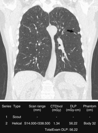
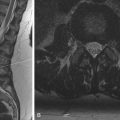
To achieve a low radiation dose for LDCT, the tube current (in milliamperes) should be adjusted. Although American College of Radiology and Society of Thoracic Radiology guidelines recommend use of AEC over fixed tube current, several studies have reported substantial dose reduction with the use of fixed milliamperage. Also, lower kilovoltage should be preferred (80–120 kV) based on the size of patients. The kilovoltage selection can be manual or automatic on scanners that have automatic kilovoltage selection. The scan coverage should be limited to the area from the lung apex to the lung bases for lung cancer screening ( Fig. 23.2 ). Scan parameters for lung cancer screening CT are summarized in Table 23.3 .
| Scan Parameters | Lung Cancer Screening and Nodule Follow-up CT | Routine Chest CT | CT Pulmonary Angiography |
|---|---|---|---|
| Scan coverage | Apex to base | Apex to adrenals | Apex to base |
| Mode | Helical | Helical | Helical |
| Time | ≤0.5 s | ≤0.5 s | ≤0.5 s |
| Pitch | Pitch ≥1 | Pitch ≥1 | Pitch ≥1 |
| Detector collimation | Wider is more dose efficient and quicker | Wider is more efficient | Wider is more efficient |
| Table speed | Faster is better | Faster is better | Faster is better |
| Reconstruction thickness | <1.5 mm | 1.5–3 mm | <1.5 mm |
| Kilovolts | 80–120 kV | 80–120 kV | 80–100 kV |
| AEC or fixed milliamperage | AEC preferred | AEC | AEC |
Lung Nodule Follow-up Computed Tomography
Demonstration of nodule stability or progression is a major reason for follow-up chest CT. The Fleischner society recommends follow-up chest CT for a lung nodule (based on size) detected incidentally on nonscreening CT. These recommendations for lung nodule follow-up are summarized in Table 23.4 . Recent studies also show the benefit of lung nodule follow-up CT based on nodule size. The chest CT protocol for lung nodule follow-up should follow the principles of lung cancer screening CT (see Table 23.3 ). Multiple prior studies have shown that lung nodules can be seen adequately at low radiation doses. Similar to lung cancer screening CT, the dose for nodule follow-up can be achieved through low fixed milliamperage based on patient size; however, the AEC technique should be preferred.
Related posts:

Stay updated, free articles. Join our Telegram channel

Full access? Get Clinical Tree


