73CHAPTER 7
Overview of Technologies for SRS and SBRT Delivery
Stereotactic radiosurgery (SRS) and stereotactic body radiation therapy (SBRT) treatments require high accuracy and precision in treatment delivery. The importance of delivering a conformal dose to the target while sparing surrounding critical organs for these high-dose single-fraction or hypofractionated treatments is paramount for their success, as discussed earlier in the book. To achieve this, highly precise and accurate radiation treatment delivery systems are necessary. Ideal systems will have the following characteristics: (a) a high dose rate so as to minimize the treatment time, thus reducing dose uncertainties from involuntary internal motion or patient movement; (b) sharp dose falloff to allow for delivery of high dose to the target without compromising adjacent normal tissues; (c) high mechanical accuracy for treatment delivery; (d) on-board three-dimensional (3D) imaging and localization hardware and software that determines the exact position of the target within the body; (e) ongoing monitoring to adjust for patient movements if necessary; and (f) the stability of radiation output with gantry rotation, collimator movement, and dose rate variation. The evolution of SRS/SBRT systems seeks to achieve these goals. The more degrees of freedom (DOF) a system has available for treatment, the more feasible it becomes to deliver a more conformal dose to the tumor with less dose to the adjacent normal organs.
Several classes of delivery systems are available to achieve this end, each having different salient traits and limitations. This chapter gives an overview of the more traditional systems for SRS and SBRT delivery in current clinical practice and explores newer alternatives. Although ancillary systems, such as ExacTrac and AlignRT, play a very important role in the positioning, monitoring, and adjustment of the patient interfraction and intrafraction motion, these are discussed only briefly here, as they are described at length in other sections of the book.
GAMMA-RAY–BASED DELIVERY SYSTEMS
Gamma-ray–based delivery systems were one of the earliest clinically available machines for SRS and have remained relevant in the field since their inception. They are known as Leksell Gamma Knife (LGK; Elekta Instruments AB, Stockholm, Sweden) or gamma units; they are exclusively used for intracranial SRS, and use cobalt-60 (Co-60) as the radiation source. Co-60 has a half-life of 5.26 years and emits two gamma rays (1.17 and 1.33 MeV) on decay that are used for therapy. This results in average beam energy of 1.25 MeV. The general concept of gamma units, although the specifics of the designs vary depending on the model, is largely 74the same. They have an arrangement of Co-60 sources that can be shielded and collimated with different aperture sizes, depending on the irradiation geometry one wants to achieve. The convergence of different beams from different angles into one focal point in the patient results in high-dose delivery to the tumor while minimizing dose to surrounding normal brain tissue. The beam arrangement group for a given target is referred to as a shot. Historically, and still commonly done to this day, patients treated with LGK would have a head frame screwed into their head. The rigid frame provides a fixed localization and coordinate system on which to base the treatment. This frame attaches to the couch and facilitates accurate localization of the tumor without imaging before treatment to ensure correct patient positioning. However, because hypofractionated treatments for lesions that are too large for SRS are becoming more common, current LGK units now provide alternatives to the traditional head frame. The LGK Perfexion has the Extend system that allows immobilization with a head frame on the basis of a dental suction technique rather than the screws. This approach is more feasible for multifraction treatments. The newest addition to the LGK line, the Icon, has 3D on-board imaging and patient monitoring capabilities and does not require a frame, but rather uses a thermoplastic mask. This system is covered in more detail later in this section.
The first Gamma Knife design, originally developed in the 1960s (1, 2), consisted of 179 Co-60 sources arranged in a hemispherical fashion covering 70° in latitude and 160° in longitude (1). The sources were collimated to rectangular beam sizes of 2.5 × 7.5 mm2 at the focal point. This design evolved to more modern versions with circular collimators instead of rectangular ones, and a larger number of sources. There are several models of LGK units in use. The older group, consisting of models U, B, and C/4C, has been discontinued and is briefly presented as some units might still be in clinical use. The subsequent paragraphs expand upon the characteristics of the newer versions, the Perfexion and the Icon.
Models U, B, and C/4C
These LGK models have 201 Co-60 sources arranged in a hemisphere. These units have both an internal fixed collimator and a collimator helmet that is external and removable. These collimator helmets have collimators, one for each source, available in four different diameters at the focus point: 4, 8, 14, and 18 mm. Only one collimator diameter can be used at a time. The sources that are not used for treatment have to be “plugged” manually by removing the collimator for those sources and replacing them with tungsten plugs. These units have a source-to-focus distance (SFD) of 40 cm. The mechanical accuracy for these units is quoted as 0.3 mm.
Models U and B are the earlier ones and they have trunnions that can be adjusted to put the patient in the correct treatment position. Both the treatment times and the stereotactic coordinates have to be manually set and there are no automatic verification checks for them or the helmet size and gamma angle (pitch of the patient’s head) (3). Models C and 4C have the automatic positioning system (APS) that adjusts the head position, independent of the couch, without human interaction. This optional feature allows for the automatic repositioning of the patient between shots that are within a predefined distance of a common point, usually ±2 cm (3). These shots are grouped in “runs.” The system is set up to retract the couch 28 cm from the radiation focus of the machine between shots to minimize the radiation dose given to the patient during repositioning. Once the run is completed, the staff enters the room to prepare the patient for the next run, if necessary, by changing the helmet and the gamma angle. This model also has improved safety measures. It uses a patient docking indicator over the frame prior to treatment to verify the gamma angle and proper docking, and it prompts the user to perform a test run prior to patient treatment (3). At this time, the system checks clearance of all the shots in the run. Once all these checks have passed, the treatment can begin. The manual positioning with trunnions can still be used. This mode still allows the system to verify the helmet size, but the other parameters must be verified manually.
Leksell Gamma Knife Perfexion
This system, which was released in 2006, has 192 Co-60 sources. The geometrical arrangement is conical, instead of hemispherical, which leads to different SFDs depending on the source position along the cone. The SFDs range from 37.4 to 43.3 cm in contrast to 40 cm for the older models (4). Most of the sources in the LGK Perfexion unit have a shorter SFD, so it displays slightly higher dose rates in comparison to the other models for sources of the same activity (5). This machine does not have primary and secondary collimators—it does not use collimator helmets. Instead, it has a tungsten 75collimator array, 12 cm thick, that is divided into five concentric rings and eight independently variable sectors (see Figure 7.1). Each sector has 24 sources, and each source has three different circular collimator sizes of 4, 8, and 16 mm. The collimator array is now smaller, so it leaves more room in the radiation cavity for increased treatment position ranges and it decreases the likelihood of collisions between the patient’s head/frame and the interior surface of the machine (4, 5).
In this machine, the collimators no longer have to be manually changed by changing the collimator helmets, but instead, the source moves over the selected circular collimator size through servo-controlled motors. Aside from the three collimator size options, the source has two other positions available: home and off. In the off position, which is used during treatment, the source is close to the collimators and can be quickly moved to treatment position (<1 second) when needed (5). In the home position, the sources are retracted several centimeters away. This is used when the machine is off or during an emergency stop.
Another notable difference implemented in the LGK Perfexion is the new patient positioning system (PPS), a robotic treatment couch. The patient is positioned at the focal point location through the use of the PPS, so APS and trunnions (manual positioning system) are no longer necessary. With this new system, the positioning speed between coordinates is increased from 0.8 mm/sec with APS to 10 mm/sec with the PPS, and the positioning repeatability is improved from 0.3 to less than 0.05 mm (4, 5). It also enhances patient comfort as now the whole body moves with the couch as opposed to just adjusting the head position separately with the APS system or trunnions (4, 6). The patient can be moved from one focus to another automatically, even if the lesions are far apart, so the chance of human error decreases, but the accuracy and stability of the PPS become a concern, especially because this model does not have a way to visually confirm the coordinates of each isocenter. However, it has been shown in the literature that the long-term mechanical stability and accuracy of this system is excellent (6). The docking system for the couch is still compatible with the standard Leksell G frame with the use of an adaptor.
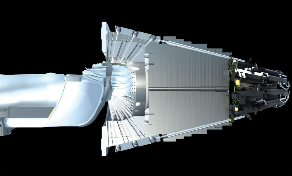
FIGURE 7.1 Illustration of the Leksell Gamma Knife Perfexion collimator.
Source: Image courtesy of Elekta AB.
There is an additional system available for the LGK Perfexion that allows users to perform multifractionated treatments—the Extend system (see Figure 7.2). This system is not a pin-based frame; it uses the patient’s dental impression and vacuum to create suction between that and the patient’s palate and thus achieve immobilization and positional reproducibility through all fractions. The level of the vacuum, or patient control unit (PCU), is monitored as it is considered a surrogate for patient motion. If the level drops below a certain threshold, the treatment is paused. The LGK Perfexion does not have on-board imaging, so the position of the Extend system is checked using the repositioning check tool (RCT). This device mounts on the Extend frame and allows the user to confirm the position of the frame using linear measurement probes in different locations.
An article by Schlesinger et al. studied the positioning uncertainty of the system in 10 patients over a total of 36 fractions and found “an overall mean radial setup displacement of 0.64 mm and an overall mean intra-fraction displacement of 0.47 mm,” and recommended careful patient selection (7). Their results are summarized in Figure 7.3, along with a schematic of the RCT. Other studies had similar findings (8–10).
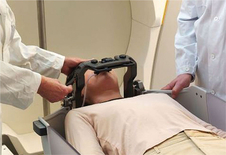
FIGURE 7.2 Extend frame for Leksell Gamma Knife Perfexion.
Source: Image courtesy of Elekta AB.
76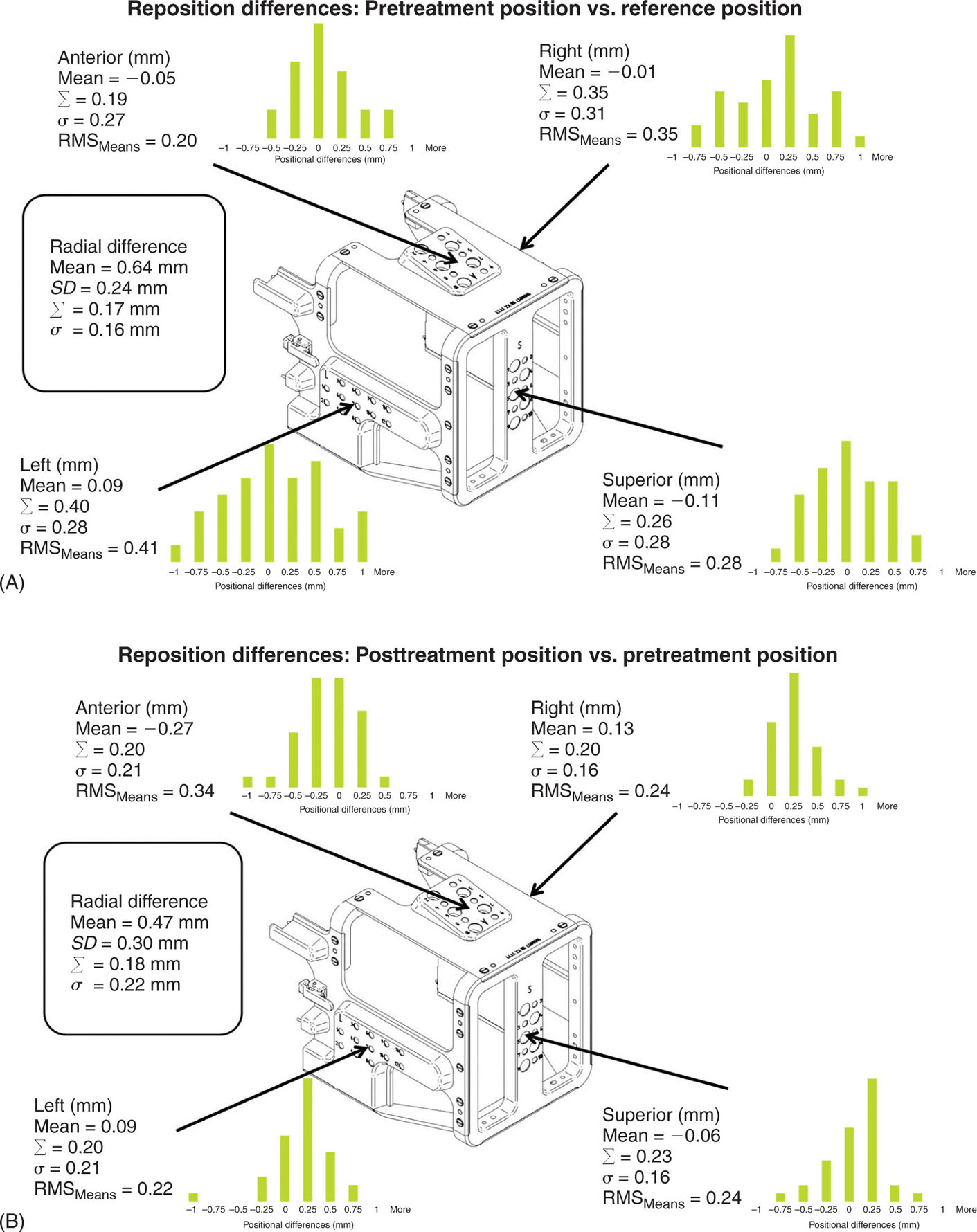
FIGURE 7.3 Illustration of the positional differences between prefraction and reference measurements (A) and prefraction and postfraction measurements (B) taken with the RCT for patients treated with the Extend system.
RCT, repositioning check tool; RMS, root mean square.
Source: Reproduced with permission from Schlesinger D, Xu Z, Taylor F, et al. Interfraction and intrafraction performance of the Gamma Knife Extend system for patient positioning and immobilization. J Neurosurg. 2012;117(suppl):217–224. doi:10.3171/2012.6.GKS12989
From a treatment planning standpoint, the LGK Perfexion allows for the combination of different beam diameters for the same focal point setup, which allows more optimal dose distributions (4). It also leads to faster treatment times because collimator changes in this system take less than 1 second, whereas the same process would add approximately 8 minutes of treatment time per collimator exchange in the previous models (11). The LGK Perfexion is broadly regarded as a safer, more efficient, and more accurate unit than its predecessors (4–6).
77Leksell Gamma Knife Icon
The Icon is the newest model of the ones presented in this section. This new system is described by Zeverino et al. in their 2017 publication (12). Although the radiation unit portion of the machine remains largely unchanged, this new system has on-board imaging and monitoring tools, making the unit more versatile for fractionated treatments (see Figure 7.4). The LGK Icon no longer requires the use of a frame; the system is compatible with the use of thermoplastic masks. The addition of a gantry with an x-ray source and detector panel for cone-beam CT (CBCT) imaging and the intrafraction motion management (IFMM) system aim to ensure that even without the use of the frame, the accuracy level of LGK is still maintained. The CBCT is external to the unit, so the patient has to be imaged and repositioned outside before being shifted into the treatment position. All throughout imaging and treatment, the patient is monitored by the infrared (IR) system that comprises the IFMM. This system has an IR reference tool with four IR markers in a fixed position. This tool is attached to the couch and it is used to track any relative motion observed between it and the patient marker (on the patient’s nose). The system can be set up so that when motion beyond a threshold is detected, either the treatment is automatically paused (active mode) or it continues, but it displays a warning message (passive mode). Although there is little clinical experience at this time to present in this text because of the newness of the unit, commissioning tests performed by Zeverino et al. show that the center of the CBCT and the center of the treatment unit coincide within a sphere of radius less than 0.2 mm, but the difference could increase because of table sag from the patient’s weight (12).
LINEAR ACCELERATOR–BASED DELIVERY SYSTEMS
Although gamma-based systems have shown great promise for SRS treatments, the lack of flexibility of use, source exchange requirements, and associated 78regulatory compliance issues make these systems far from ideal for most clinics. Linear accelerator (linac)–based delivery systems are multipurpose and do not use radioactive material; their development for SRS treatments was the next logical step. Since their initial use for this purpose in the 1980s, manufacturers have developed systems that are optimized for SRS and SBRT treatments by having finer resolution multileaf collimator (MLC), higher dose rates, greater mechanical accuracy, and robust integrated image guidance for patient positioning and intrafractional monitoring. Modern linacs designed to handle SRS/SBRT treatments now offer flattening filter-free (FFF) beams. These beams can achieve much higher dose rates than their flattened counterparts and have a softer energy spectrum. These high dose rates in conjunction with noncoplanar beam or arc arrangements yield fast conformal treatments that allow for high-dose delivery to the target, sharp dose gradient, normal tissue sparing, and a reduction in the likelihood of patient motion because of the much shorter treatment times. The development of 4pi treatments with simultaneous couch and gantry rotations is well underway, although it is not used clinically yet (13).
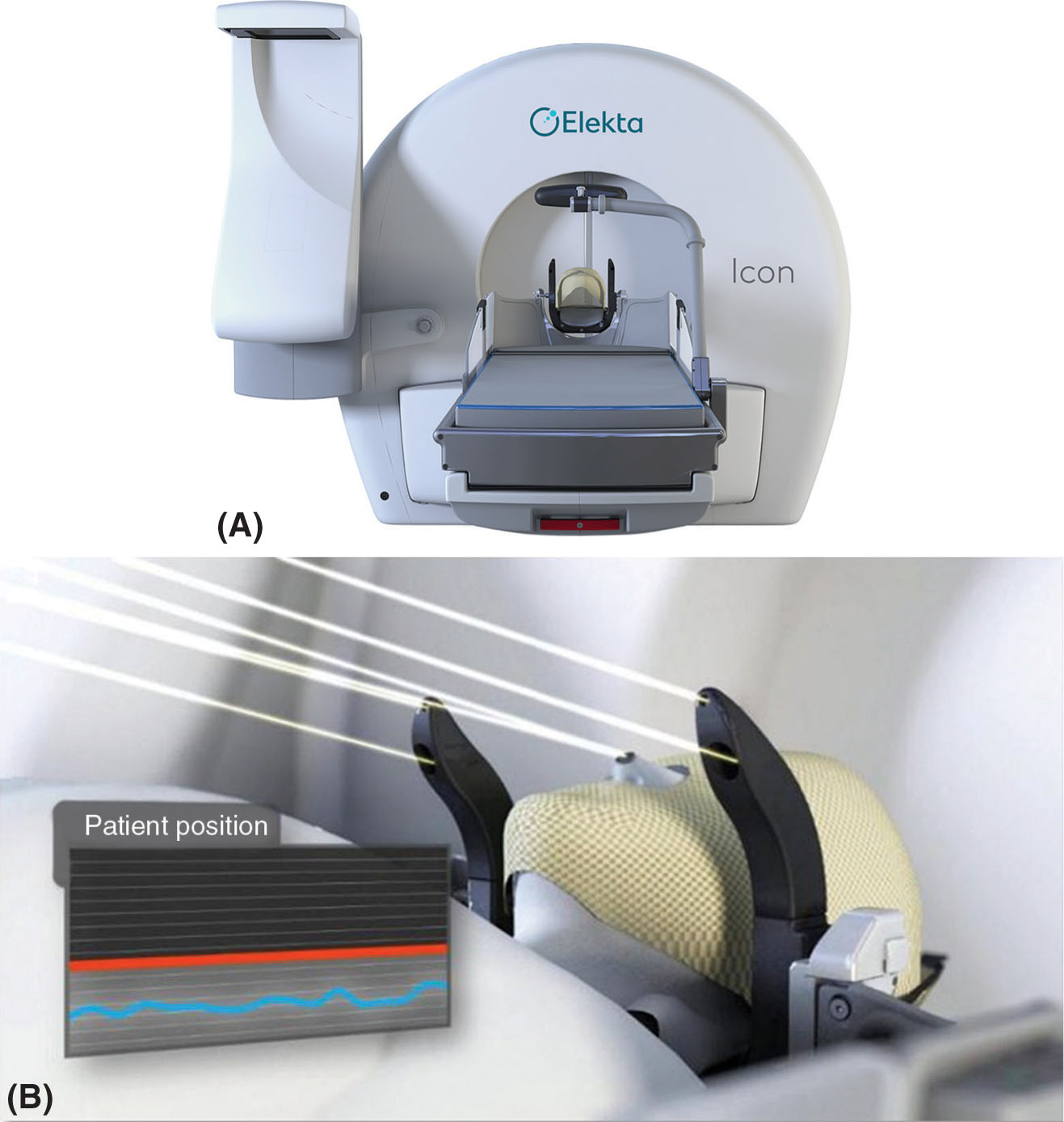
FIGURE 7.4 (A) Leksell Gamma Knife Icon with the CBCT arm on the left side of the machine and the HDMM system on the right of the couch. (B) A close-up of the HDMM system with the four infrared markers on the reference tool and one on the patient’s nose.
CBCT, cone-beam CT; HDMM, high-definition motion management.
Source: Image courtesy of Elekta AB.
Even platforms that are not specifically designed for radiosurgery purposes can achieve those traits through the use of add-on accessories and ancillary systems. Fixed circular collimators, or cones, are tertiary collimators that attach to the linac and provide smaller field sizes with sharper penumbra. They are desired for the treatment of small brain lesions of spherical or near-spherical shape. These cones have field size diameters that typically range from 5 to 40 mm and an approximate height of 12 cm, with the specific design dimensions and available field sizes depending on the manufacturer (14, 15). Because cones attach to the gantry and come closer to the patient’s skin than integrated MLC systems, their penumbra is sharper. However, the reduced distance between the cone and the patient also leads to higher chances of collision. The use of cones is restricted to SRS because of the smaller field sizes they provide, their circular field shape, and clearance limitations. Modern cones, such as the Integrated Conical Collimator Verification and Interlock (ICVI) system by Varian (Varian Medical Systems, Palo Alto, California), have safety features such as automatic jaw settings with cone insertion (16). The jaw positions need to be properly set when using cones so that no radiation is delivered outside the outer cone diameter. By having an automatic setting, this voids the possibility of incorrect jaw positions that could lead to severe overdoses of normal brain tissue. The penumbra for 6-MV beams from cones such as the ICVI is less than 2 mm at dmax with source-to-axis distance (SAD) = 100 cm (17).
Available add-on devices also include MLCs. There are many models from different vendors available (18–20). The m3 micro-MLC (Brainlab AG, Feldkirchen, Germany) is described here as an example of this types of devices. The m3 is a popular model that is compatible with linacs from all the main vendors (18). This 30-kg device can be manually mounted on the gantry, when the gantry is at 180°, using a specially designed trolley. The added weight on the gantry has been shown to have no significant effects on its mechanical stability (21). The MLC has 26 leaf pairs of varying widths. The central 14 pairs have a width of 3 mm; adjacent to these, there are three pairs of 4.5-mm-width leaves on either side, and the outer six pairs, three on each side, have a width of 5.5 mm. These leaves interdigitate, are 12 cm long and 6 cm thick, can overtravel 5 cm, have a positional precision of 0.1 mm, and can define a maximum field size of 10.2 × 10 cm2 at isocenter (21). They travel perpendicular to the central axis of the beam with a maximum speed of 1.5 cm/sec and their design accounts for beam divergence through the three straight edges of each leaf-end. The top edge matches the beam divergence when the leaf is fully extended, whereas the bottom edge matches the beam divergence for a fully retracted leaf. The center portion is straight to align with central axis. The cross-section of the leaves is designed to match the divergence of the beam perpendicular to the direction of travel. When using this accessory, the internal MLC of the linac should be fully retracted to avoid interaction with the beam. The average penumbra reported for 6-MV fields shaped to 2 × 10 cm2 with the m3 is less than 2.5 mm at a dmax with SAD = 100 cm, and the average MLC transmission and leakage are 1% to 2% and 1.2% to 2.8%, respectively, depending on the publication (21, 22). Just as described with cones, the diminished distance between the collimating device and the patient leads to sharper penumbra but may also result in increased treatment clearance issues. The clearance from isocenter of the m3 system is 31 cm. The m3 micro-MLC is integrated with the Novalis system by Varian. The Novalis system is described in more detail in the following text.
Ancillary devices for patient imaging, positioning, and monitoring are discussed later in the chapter. There are also respiratory motion management 79options for SBRT that aim to reduce or account for the tumor’s movement during treatment because of respiration. These auxiliary systems can be used to either put the patient in breath-hold or gate the beam. These include the Elekta Active Breathing Coordinator and the Real-Time Position Management (RPM) system by Varian. Although these can be useful to reduce treatment margins by minimizing tumor motion during irradiation, they should be used with care, and proper patient selection should be performed. The ABC is a spirometer-based system that measures the patient’s inhaled volume of air during respiration. On the basis of this information and the air–volume threshold selected for breath-hold, the machine engages and maintains the patient at a specific volume of air in his or her lungs while the beam is on. However, if air is being exchanged outside the breathing tube, the system will not measure it and the breath-holds will be inconsistent. Hence, care must be taken. For RPM, the system tracks the motion of the IR marker box that is placed on the patient’s torso. This motion provides the breathing trace for the patient. The system inherently assumes that the motion of the tumor correlates with the external surrogate tracked by RPM. If this assumption is flawed, the treatment will not be delivered as intended. These systems can sometimes be interfaced with the linacs that are described next to automatically gate the beam, or they can be used with manual gating.
Varian Systems
There are several linac models by Varian that can be used for SRS and SBRT treatment delivery. Some of them are specifically designed for radiosurgery, such as the Novalis and Edge platforms, and others can reach that capability through the use of ancillary systems such as the ones described earlier. This section focuses on the description of the Novalis Tx, TrueBeam STx, and Edge systems, but other models such as Trilogy can also be used for SRS/SBRT, especially when using ancillary devices.
The Novalis Tx system is a popular radiosurgery platform that includes technology developed by both Varian (Varian Medical Systems) and Brainlab (Brainlab AG). The linac in this platform is very similar to the Trilogy with its on-board imaging capabilities (on-board imaging and MV panel), but it comes equipped with high-definition MLC (HDMLC) and the ExacTrac system (23). The ICVI system can also be used, if desired. The HDMLC has 32 inner leaf pairs of 2.5 mm width at isocenter with 14 outer leaf pairs on either side (28 total) of 5 mm width at isocenter. The leaves in this collimator can interdigitate and overtravel by 20 cm, but adjacent leaves cannot be positioned more than 15 cm apart (24). The maximum leaf speed is 2.5 cm/sec and the maximum carriage speed is 1.2 cm/sec. The maximum field size it provides is 40 × 22 cm2, but when performing intensity-modulated radiation therapy (IMRT) the maximum size is 32 × 22 cm2. Aside from the conventional beams with dose rates up to 600 MU/min (maximum dose rate for standard beams 6–25 MV), this platform also offers a high-dose rate (1,000 MU/min), 6-MV beam for SRS treatments. This beam has a different flattening filter that permits a higher dose rate but restricts the field size (23). When treating with the SRS beam, the maximum size is 15 × 15 cm2. This machine has a clearance radius (from the interface mount to isocenter) of 41.5 cm. The average penumbra measured for this machine parallel to the leaf motion in a 10 × 10 cm2 field at dmax with source-to-surface distance (SSD) = 100 cm is 2.6 mm (SRS 6 MV), 4.2 mm (6 MV), and 6.2 mm (10 MV) (25). Penumbra values perpendicular to the leaf motion are smaller. The positioning accuracy of the HDMLC leaves is 0.25 mm (24), and the mean MLC transmission is less than 1.2% for 6 MV (23, 25). The isocenter accuracy between the gantry and the collimator for this system is within a 0.5-mm radius, and a 0.75-mm radius when including the couch (24). The addition of the ExacTrac system in the platform allows for accurate patient setup and intrafraction monitoring on the basis of two x-ray imaging panels mounted on the ceiling with their corresponding sources built into the floor. These allow for imaging at any couch angle, even during treatment. It also has an optical tracking device for IR markers. Predefined marker arrays are available or markers can be manually placed on the patient for position monitoring and precise couch motion. This system is further discussed later in the chapter. If a 6-DOF couch is purchased with the system, ExacTrac will provide the three translational and three rotational shifts necessary to achieve the optimal treatment position. These couches usually have a rotational range for roll and pitch of ±3°.
The TrueBeam STx is a treatment delivery platform with three photon energies selectable between 4 and 20 MV (4 MV, 6 MV, 6 MV FFF, 8 MV, 10 MV, 10 MV FFF, 15 MV, 18 MV, 20 MV) and a range of electron energies from 4 to 22 MeV. It also offers both flattened and FFF beams. The advantage of FFF beams is their higher dose rate 80because they allow for faster treatment delivery. The maximum dose rate for 6 MV FFF is 1,400 MU/min and that of 10 MV FFF is 2,400 MU/min. Although the control system for this linac (Maestro control architecture) and a lot of the gantry elements have been redesigned for enhanced performance in comparison to previous models (26), field shaping is still achieved with the HDMLC formerly described for the Novalis Tx system, and the manufacturer-provided gantry, collimator, and couch isocenter accuracy is also the same (27). The ICVI system is available for TrueBeam as well.
The Edge radiosurgery system is the latest model from Varian and it is marketed toward SRS and SBRT treatment delivery (see Figure 7.5). This platform includes a TrueBeam linac but with a smaller profile, the purpose of which is to fit into smaller vaults (26, 28). It offers only 6 and 10 MV energies with standard and high-dose rate modes (FFF beams). Field shaping is still performed with either HDMLC or the ICVI system. As opposed to the Novalis Tx system, the Edge comes with the Optical Surface Monitoring System (OSMS) instead of the ExacTrac. The OSMS tracks the surface of the patient for positioning and monitoring. This equipment has the same technology as AlignRT (Vision RT, London, UK) and it is explained in more detail later in the chapter. The Edge comes with an integrated PerfectPitch 6-DOF couch (positional accuracy of ≤0.5 mm and ≤0.3°); it allows for intrafraction kV/MV imaging triggered on the basis of gantry position, MU delivered, time, or respiratory signal, and it has a high-contrast MV imaging mode (2.5 MV) with extended field of view (28). It offers the Calypso system for extracranial real-time tracking. This system can be used with other platforms as well; it is not exclusive to the Edge. It tracks the target using the electromagnetic signal from the beacon transponders implanted in the patient, and it can interface with the machine to adjust the couch position or gate the beam on the basis of the received signal.
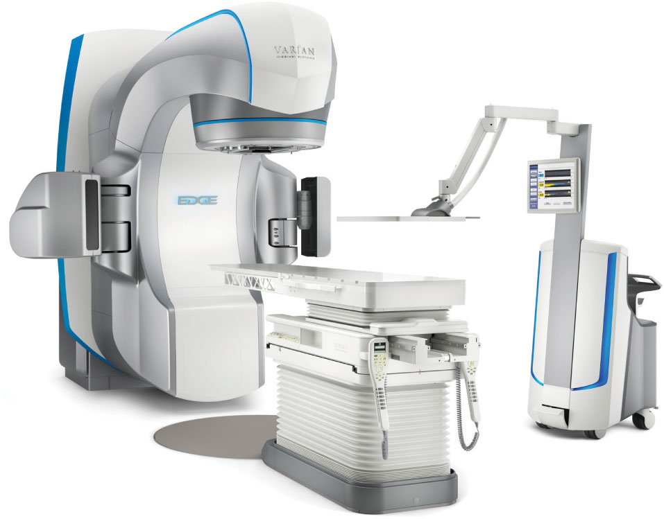
FIGURE 7.5 Varian Edge with the PerfectPitch couch and the Calypso extracranial tracking system on the right of the image.
Source: Image courtesy of Varian Medical Systems, Inc. All rights reserved.
Elekta
Elekta offers different linac models that are capable of SRS/SBRT delivery. Here we describe the Synergy S and Versa HD.
The Elekta Synergy S (Elekta Oncology Systems, Crawley, UK) system has on-board planar kV and CBCT capabilities for patient position verification. In this system, the field shaping is performed by the beam modulator (BM) head. The BM is an MLC that consists of 40 leaf pairs with leaves of 4 mm width at isocenter. The leaves are 7.5 cm thick, travel perpendicular to the beam axis, and have rounded leaf tips. The maximum field size available with the BM is 16 × 21 cm2. There are no movable backup jaws in the Synergy S; the field shape is solely defined by the MLC (29). The BM leaves are capable of interdigitation, have a maximum leaf speed of 3 cm/sec (30), and have a position reproducibility of 0.1 mm (29). The penumbra of this system is much larger along the direction of motion of the leaves than perpendicular to it. These values have been reported in the literature by Podder et al. as approximately 4.5 and 3.3 mm, respectively, for 4.8 × 4.8 cm2 fields at dmax and SSD = 100 cm (31). This same article measured the average and maximum MLC leakage of the BM as 0.9% and 1.6%, respectively. This machine has several photon energies available but does not offer FFF beams, so the maximum dose rate available is 600 MU/min (18).
The Versa HD linac has been designed to be an efficient delivery system for both conventional and SRS/SBRT treatments (see Figure 7.6). It has both flattened and FFF photons beams (6 MV, 6 MV FFF, 10 MV, 10 MV FFF, 15 MV or 18 MV), as well as electrons (4–15 MeV). As in the Varian machines, the FFF beams have a maximum dose rate of 1,400 MU/min for 6 MV FFF and 2,400 MU/min for 10 MV. The maximum field size available is 40 × 40 cm2.
This linac comes equipped with the Agility collimator. This collimator was redesigned to improve performance for dynamic treatments and can also be installed in other Elekta linacs, if desired. It is installed as the upper level of collimation of the head that allows for a clearance from isocenter of 45 cm. The Agility head has been described and characterized by Thompson et al. in their 2014 publication (32). It has 80 interdigitating single-focus leaf pairs with curved leaf tips. The leaves have a thickness of 9 cm and a width of 5 mm at the isocenter (all leaves have the same width). They have a maximum overtravel of 15 cm and a positional uncertainty of 0.1 ± 0.2 mm over their complete range of travel (32). The large overtravel range is because of the dynamic leaf guides (DLGs) on which the leaf banks are mounted. Although the leaves themselves have a maximum extension of 20 cm, the DLG can travel an additional 15 cm. The DLGs also allow the leaves to move faster. The leaves have a maximum speed of 3.5 cm/sec, but the DLG can move at 3 cm/sec. This results in an effective leaf speed of 6.5 cm/sec (32). The interleaf gap is designed to minimize leakage achieving an average transmission through the MLC profile of 0.35% with a measured maximum (corresponding to interleaf leakage) of 0.41% for 6-MV beam (32). The penumbra reported for this collimator for a 6-MV beam at dmax and a SAD = 100 cm was 4.8 mm for a 10 × 10 cm2 field (32). Two y-shaped sculpted diaphragms traveling perpendicular to the leaves allow for rapid field length changes during dynamic treatments. The overtravel for the y-diaphragms is 12 cm (33). Figure 7.7 illustrates the Agility design. The Agility MLC, along with the four-dimensional (4D) soft-tissue visualization of the on-board imaging system, can be used for dynamic real-time tracking of the tumor (34). This functionality can result in the reduction of motion-related margins, which would spare healthy tissue without compromising coverage of a moving tumor. Versa also comes equipped with planar kV imaging, CBCT, and MV imaging capabilities. The gantry, collimator, and treatment couch isocentricity of this machine are 1, 0.7, and 0.7 mm, respectively, as measured by Narayanasamy et al. (35). Even though the maximum FFF beam MU rate is the same for the Varian TrueBeam and the Versa HD, the Versa has shorter treatment times (36). This is because the Agility MLC can move faster than the Varian MLC, so dose modulation in the Versa HD does not require a decrease in the dose rate during treatment delivery.
81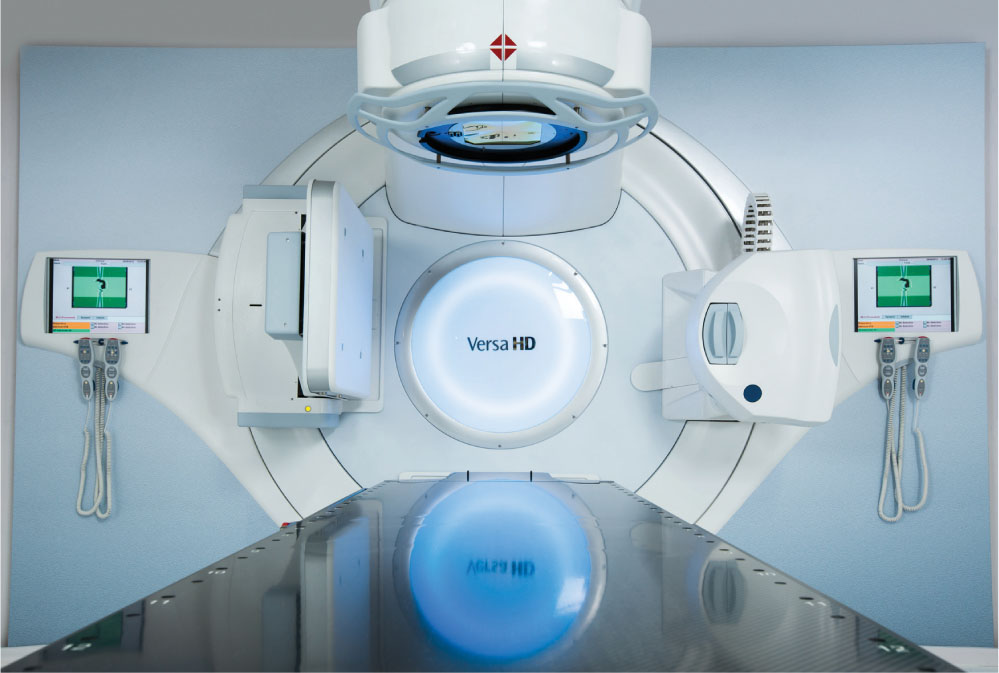
FIGURE 7.6 The Versa HD linear accelerator.
Source: Image courtesy of Elekta AB.
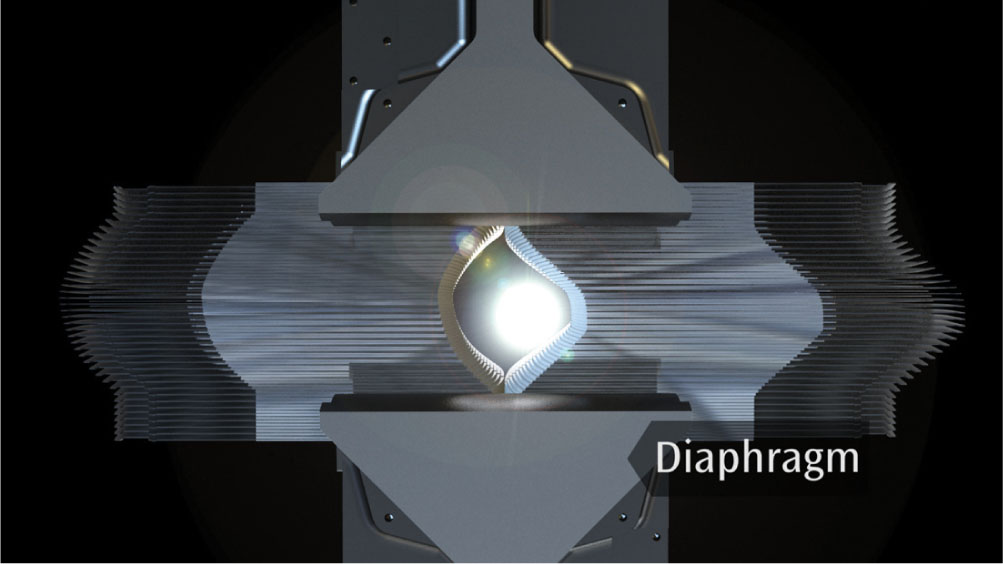
FIGURE 7.7 The Agility collimator with MLC, dynamic leaf guides, and sculpted diaphragms from the patient’s eye view.
MLC, multileaf collimator.
Source: Image courtesy of Elekta AB.
CyberKnife
The CyberKnife (Accuray, Inc., Sunnyvale, California) system presents an option in radiation therapy (RT) that differs from the standard linac. It is a linac mounted on a robotic arm that has 6 DOF and can move in a wide range of directions to perform nonisocentric treatments. This machine can deliver radiation from 1,200 different directions (more than 1,600 in the G4 and M6 models) and, as a result, is capable of achieving highly conformal dose distributions without sacrificing dose homogeneity (37). The only positional restrictions are dictated by the collimator assembly collision detector (38).
The X-band waveguide design makes the linac sufficiently small and lightweight (approximately 160 kg) to be mounted on and moved by an industrial robotic arm (38). It produces 6MV FFF radiation beam with a dose rate of 1,000 MU/min at SAD = 80 cm (39). The original system was designed for SRS treatments and therefore it offered radiation fields exclusively on the basis of circular collimators 82of sizes ranging from 5 to 60 mm (5, 7.5, 10, 12.5, 15, 20, 25, 30, 35, 40, 50, and 60 mm nominal size at SAD = 80 cm) (40, 41). Newer versions now allow for different options for beam shaping such as the InCise MLC and the Iris variable aperture collimator. These are further described later.
Aside from the novelty of nonisocentric delivery and the flexibility of the robotic arm, the CyberKnife also has integrated image guidance that allows for real-time tracking and positioning correction of the radiation beam on the basis of the patient’s anatomy or internal fiducial markers. This is achieved with the use of two orthogonal x-ray systems that intersect at an imaging center 92 cm above the floor (41). Each detector panel is mounted on either side of the treatment table. The x-ray sources are rigidly mounted on the ceiling facing toward their corresponding imaging detector panel. The source to imaging center distance is 220 cm (41). Older machines (G3) have smaller amorphous silicon detectors (20 cm × 20 cm) and they are mounted at 45° on stands that protrude 61 cm from the floor (38). This is what resulted in the more limited number of possible treatment directions quoted earlier for the older model. Newer versions (G4 and M6) have 40 cm × 40 cm amorphous silicon panels that are installed either flush to the floor or 15.2 cm above it at 45° (38). These imagers periodically acquire images (every few minutes) that are compared with the digitally reconstructed radiographs (DRRs) from the planning CT to check the patient position throughout the treatment. The system uses that information to adjust the position of the radiation beam to ensure continuous accurate dose delivery to the target (37). Translations of up to 10 mm (or 25 mm when using the respiratory tracking system) and rotations of 1° in roll and pitch, and 3° in yaw can be automatically corrected by the system; anything greater than those limits has to be corrected manually (42). There are three tracking methods used by the CyberKnife system: bony structure tracking (includes 6D Skull and Xsight Spine tracking, which is used for spine targets), fiducial tracking, and soft-tissue tracking (Xsight Lung which allows for lung tumor tracking without fiducials, on the basis of the difference between target and lung tissue densities) (38).
Skull tracking is used when treating intracranial lesions or tumors that are fixed relative to the skull. The method uses high-contrast bone information to register orthogonal images, using all of the anatomy as the region of interest, with the DRRs, and calculates the 3D rigid transformation necessary for alignment (43). Phantom studies for this algorithm in the CyberKnife G4 have shown a total clinical accuracy of 0.44 ± 0.12 mm for intracranial lesions (44). The Xsight Spine algorithm, also on the basis of high-contrast bone information, was developed to allow for the treatment of lesions in the spine without requiring the implantation of fiducial markers for tracking. There are several articles studying the accuracy of this tool, as correct positioning when treating close to the spinal cord is crucial to the success of the treatment (42, 45, 46). The basic workflow of the algorithm is to compare the orthogonal images obtained during treatment (every 1–1.5 minutes) (42, 46) with the DRRs from the planning CT scan and register them using a “grid-based, automatic, nonrigid formalism” (45). The region of interest for the registration typically encompasses the vertebra of interest plus two adjacent ones (43). The DRRs are created using a 0.5-mm step size to improve their quality (45), and the skeletal structures in both sets of images are enhanced through a series of postprocessing filters to improve the registration (46). All three studies showed submillimeter tracking precision.
Xsight Lung, as opposed to the two previous methods, accomplishes patient alignment in two steps: global alignment and tumor tracking. During global alignment, the system uses the region of the spine closest to the target to ensure proper overall positioning. Second, the system moves the couch so the target is in or close to the imaging center for tracking. Tumor tracking is performed by registering the periodically acquired images to the DRRs from the planning CT. In order for this process to work correctly, the tumor has to have sufficient contrast relative to the surrounding lung tissue. Consequently, both size and location of the lesion affect the reliability of the tracking method. The algorithm works best for tumors that are larger than 1.5 cm (43). The Xsight Lung is often paired with the Synchrony tracking system. Synchrony uses the information from the x-ray images to track the tumor position while simultaneously reading the breathing trace for the patient from the signal of three light-emitting diodes (LEDs) on the patient’s body (47). The tumor position is inferred using Xsight Lung or from fiducial markers (for lung tumors with borders that are not clear enough, or tumors in other organs such as the liver). The software then creates a model to correlate the internal position of the target with the external breathing trace to predict where the linac arm should be in 115 milliseconds so it can adjust 83its position without a significant time lag as the target moves with breathing. The validity of this model is checked by the system, and updated if necessary, every 1 to 6 minutes (47, 48). If the system detects a deviation larger than 5 mm, treatment is interrupted and a new correlation model has to be created (47). Studies investigating the performance of Synchrony are available in the literature and report varying results (positional errors of 2–4 mm) depending on the treatment site (47–49).
Fiducial marker tracking is also an option with the CyberKnife platform (43). This requires the implantation of typically three to five radiopaque fiducial markers in or close to the target approximately a week before the planning CT scan. The time lag between implantation and simulation allows for the markers’ position to stabilize. The positions of these markers are known in the DRR and image registration is performed on the basis of them. The Synchrony system can also be used with fiducial marker tracking (49).
As mentioned earlier, newer CyberKnife units have multiple collimation options available: the standard fixed circular collimators, the Iris variable aperture collimator, and the InCise MLC (see Figure 7.8). The Iris was first introduced in 2008 (50). Through its two hexagonal banks of tungsten segments offset by 30° from each other, Iris has the ability to create fields equivalent to those obtained with any of the fixed circular collimators. The advantage arises from the fact that the Iris can change sizes automatically, hence easily allowing the use of any collimator size at any angle without penalty of extra collimator exchange time, resulting in shortened treatment times (50).
The InCise MLC system, with leaves of 2.5 mm width and a maximum field size of 11 cm × 9.75 cm at 80 cm SAD (39), was quickly updated to InCise 2 MLC which consists of tungsten leaf pairs that are 3.85 mm wide at 80 cm SAD, and can provide a maximum field size of 11.5 cm × 10 cm (41). The average transmission over the MLC is less than 0.5% and the leaves’ positional accuracy is less than 0.5 mm (39). The leaves are capable of both full overtravel and full interdigitation (41). Kathriarachchi et al. performed a planning study on 10 prostate cancer patients to compare the performance of the Iris with that of the InCise for CyberKnife treatments (50). They found that similar target coverage, conformity index (CI), and homogeneity index were achievable with both, but that InCise displayed a more rapid dose falloff, illustrated by the smaller gradient index (GI) obtained for the MLC plans. MLC-based treatment plans had also faster delivery times (36% reduction) and a smaller number of MU (42% reduction). Jang et al. studied the effects of using InCise to replan 24 patients treated earlier for brain metastases at their institution with CyberKnife and fixed collimator/Iris (51). In this work, they found that target coverage and mean target dose were comparable between the two sets of plans, but that cone/Iris plans had slightly better CIs (see Figure 7.9). However, just like in the previous study, the treatment time was greatly reduced with the use of MLC, leading them to the conclusion that it may be a useful option for multitarget treatments or treatments with delivery time constraints. It is important to note that treatment times with the CyberKnife, regardless of the collimation used, are considerably longer than with other systems (52, 53). This is discussed in further detail in the section “Performance Comparisons.”
TomoTherapy
The Hi-Art I, a TomoTherapy system prototype developed and installed at the University of Wisconsin-Madison, was the first dedicated IMRT machine with integrated on-board imaging (54) introduced in the clinic in 2003 (55). Helical TomoTherapy machines function in a way that is analogous to imaging with helical CT scanners. In TomoTherapy, the FFF 6-MV linac is mounted on a slip-ring gantry that allows for its unrestricted full rotation around the patient, using SAD technique and a bore diameter of 85 cm. The nominal maximum dose rate at dmax, according to the product specifications for the TomoHD unit, is 850 cGy/min (56). As the source rotates, the couch translates through the gantry achieving a helical treatment delivery. The fan beam extends 40 cm laterally, has a beam stopper opposite to the source that alleviates shielding requirements, and can be collimated by adjustable jaws (with a thickness of 13.5 cm of tungsten) to 1, 2.5, and 5 cm in the superior–inferior dimension (56). Additional modulation is achieved with the binary 64-leaf collimator in which pneumatic drives open and close the leaves in specific time intervals to attain the desired dose distribution (56). These leaves are 95% tungsten, 10 cm thick, and 0.625 cm wide (55). During treatment planning, the gantry rotation is divided into 51 sections called projections. The treatment is delivered inside the gantry, so the lasers for patient setup are in a virtual isocenter that is located 70 cm from the true treatment isocenter in the superior–inferior direction (57, 58). New Tomo-Therapy units also allow for treatment delivery with static fields at discrete angles when using the TomoDirect mode. This affords users the possibility of performing treatments with their TomoTherapy unit using 2 to 12 different gantry angles and the level of modulation, if any, of their choice (56). In this mode, the gantry stays fixed while the couch moves through it. This process is repeated for every fixed gantry angle in the plan. TomoDirect is typically geared toward routine treatments such as whole breast RT with tangential fields. A description of its use for treatments such as SRS/SBRT could not be found in the literature by the authors. However, its use for prostate and lung RT with conventional fractionation has been investigated and the results showed that TomoDirect delivers higher dose to the rectum in prostate treatments, but smaller lung V5 (lung volume receiving 5 Gy) in thoracic wall and lung target treatments (59). The same study shows that use of TomoDirect did not reduce treatment times.
84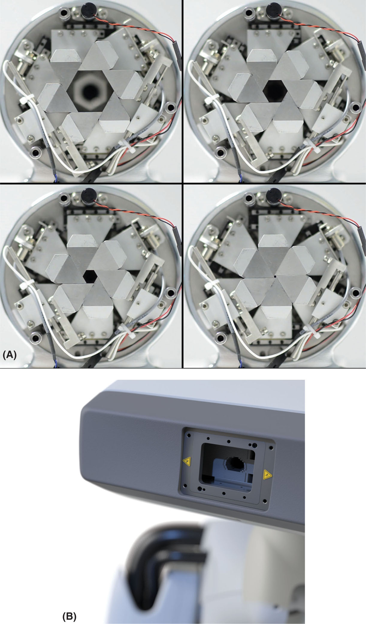
FIGURE 7.8 Closeup of the CyberKnife (A) Iris collimator and (B) InCise MLC.
Source: © 2018 Accuray Incorporated. All Rights Reserved.
85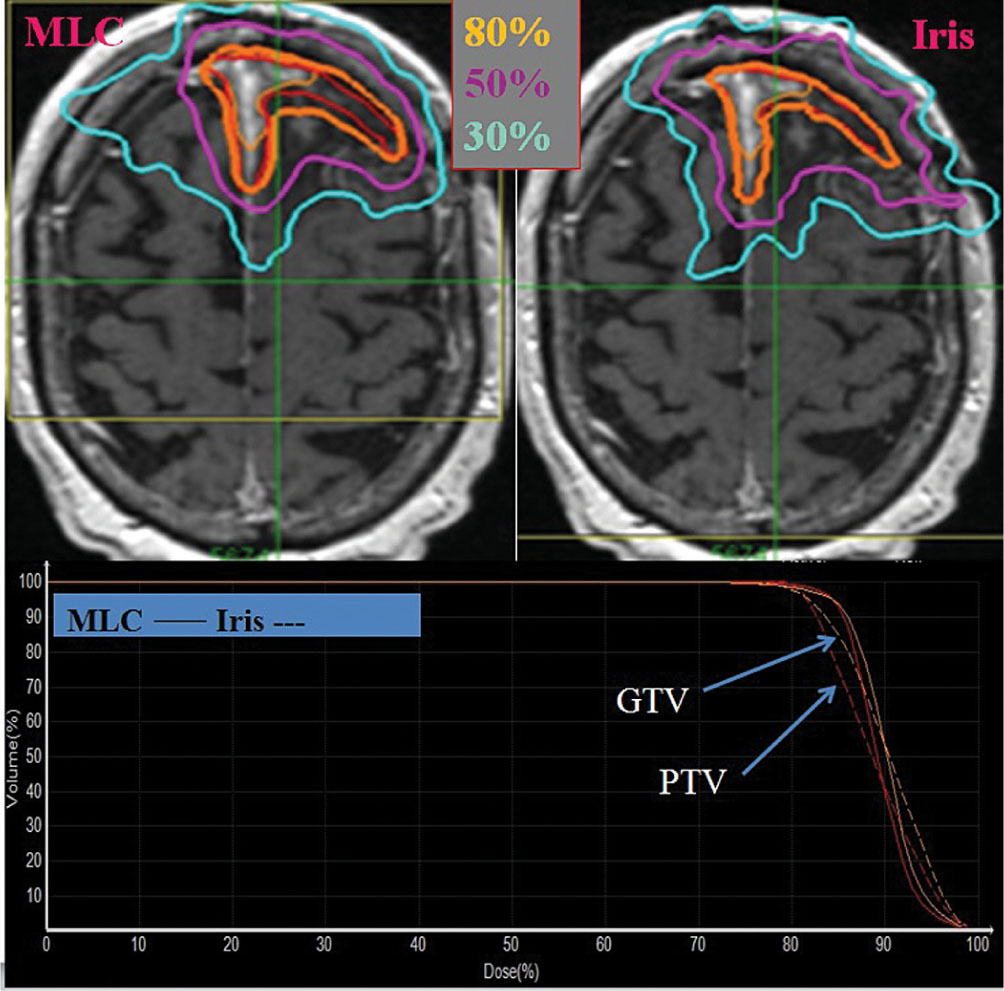
FIGURE 7.9 Results from the study by Jang et al. (51) showing the difference in dose distributions from an MLC-based and cone/Iris-based plan. The red contour indicates the target. Solid lines in the DVH represent MLC and the dashed line represents Iris plans.
DVH, dose–volume histogram; GTV, gross tumor volume; MLC, multileaf collimator; PTV, planning target volume.
Source: From Jang SY, Lalonde R, Ozhasoglu C, et al. Dosimetric comparison between cone/Iris-based and InCise MLC-based CyberKnife plans for single and multiple brain metastases. J Appl Clin Med Phys. 2016;17(5):184–199. doi: 10.1120/jacmp.v17i5.6260
TomoTherapy systems have a detector mounted opposite to the source (source-to-detector distance [SDD] = 145 cm) to allow for image acquisition with a 3.5-MV beam (see Figure 7.10) (55). This detector is an arc-shaped, single-row xenon detector array with a field of view diameter of 39 cm, and a matrix size of 512 × 512 pixels (0.78 mm pixels) (56). The images are typically acquired with a gantry rotation speed of 10 seconds per rotation, with a nominal y-setting of 4 mm, and different pitch settings (1, fine; 2, normal; 3, coarse) depending on the slice thickness desired (2, 4, and 6 mm, respectively) (60, 61). Volumetric reconstruction is performed with the filtered back-projection algorithm (55) and the images are registered to the planning CT images prior to treatment to ensure proper patient positioning. Because the scans are acquired with MV energy, the low contrast resolution is limited and the images are noisier when compared to kV scans (61), but the images are less sensitive to artifacts from high-Z materials such as dental fillings (62). The dose per scan depends on the selected settings, but ranges between 1 and 3 cGy (60). The Planned Adaptive software (TomoTherapy Inc., Madison, Wisconsin) allows for the use of megavoltage CT (MVCT) scans for treatment planning. This software resamples the MVCT images and combines their information with the kilovoltage CT (kVCT) set originally used for planning by replacing the anatomy of the kVCT images that falls within the MVCT field of view (FOV) with the MVCT scan (63). This enables the option of adaptive planning if the anatomy displays changes from simulation.
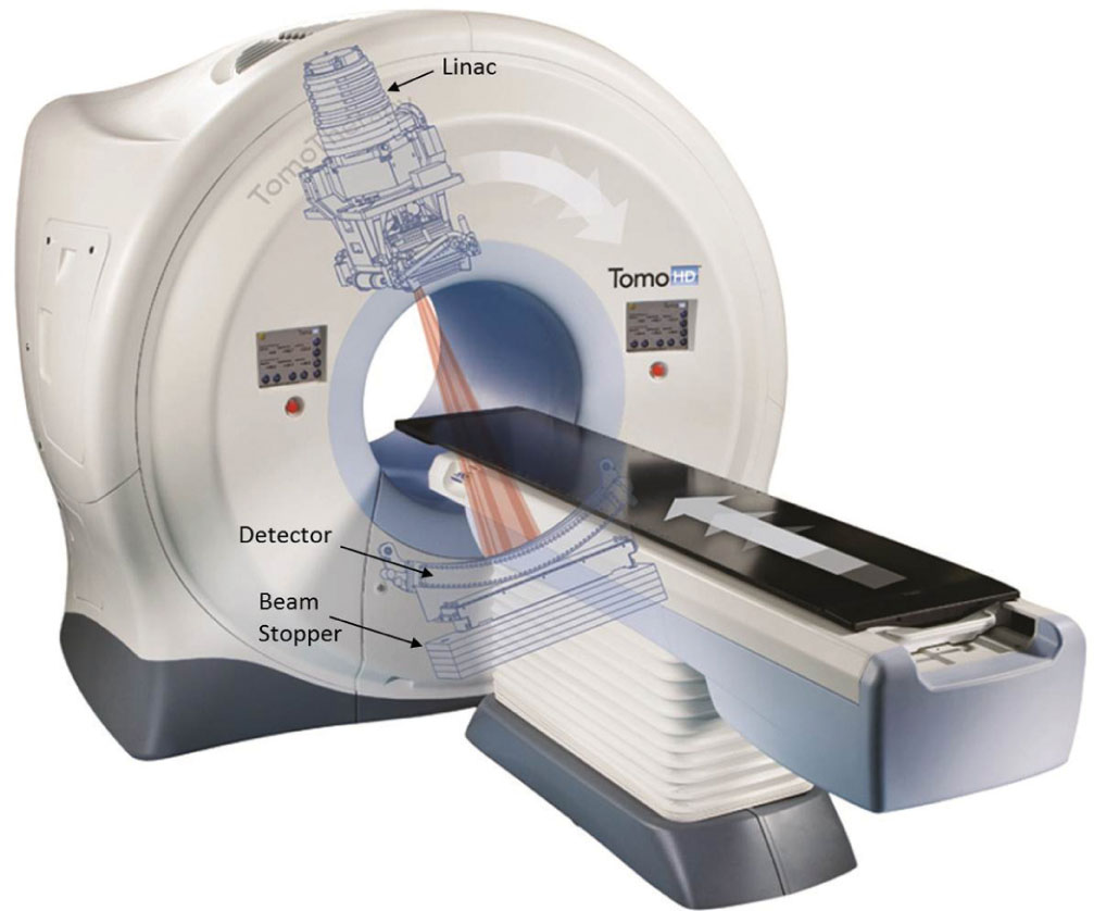
FIGURE 7.10 Picture of a TomoTherapy system (TomoHD) with the overlay of the internal components. Labels of main components added to the figure for clarity.
Source: © 2018 Accuray Incorporated. All Rights Reserved.
Originally, the jaw settings for TomoTherapy treatments were fixed for a given treatment plan, even while passing over the cranial and caudal edges of the target, which would lead to widening of the longitudinal penumbra (64). To reduce this effect, thinner slices (smaller jaw openings) were used for treatment at the expense of prolonged beam-on time. With the advent of TomoEDGE, this issue has been mitigated as the superior and inferior jaws can now move independently to minimize craniocaudal penumbra broadening (see Figure 7.11) (64, 65). The use of this new feature allows for faster treatments because the 5-cm jaw setting can be used in more cases without overcovering the target at the cranial and caudal ends (64). Another performance enhancement in newer machines is more stable output. Older Tomo-Therapy units have reported higher output variations (±2%, or higher) because of the absence of a dose servo system (57, 66). However, the newer machines have a dose control system that suppresses output variation to within 0.5% (67).
86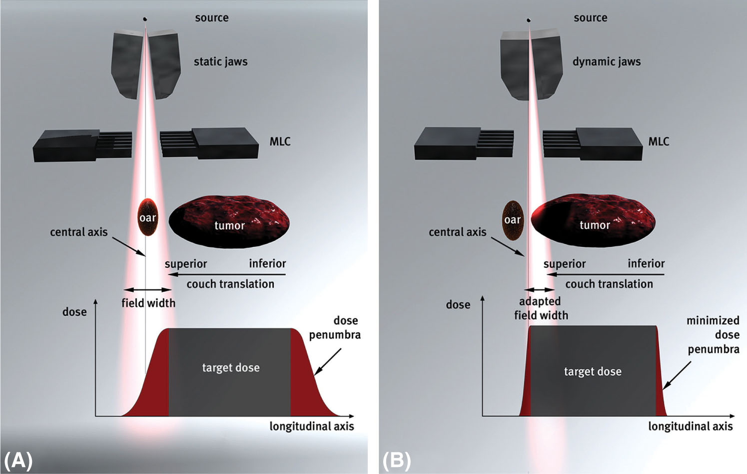
FIGURE 7.11 Comparison between (A) static jaws (the original TomoTherapy jaw design) and (B) dynamic jaws (the TomoEDGE design).
MLC, multileaf collimator.
Source: Reproduced with permission from Sterzing F, Uhl M, Hauswald H, et al. Dynamic jaws and dynamic couch in helical TomoTherapy. Int J Radiat Oncol Biol Phys. 2010;76(4):1266–1273. doi: 10.1016/j.ijrobp.2009.07.1686
TomoTherapy can be used for SRS and SBRT procedures. Helical TomoTherapy allows for the simultaneous treatment of multiple targets easily without having to move the patient from one treatment isocenter to the next, like with conventional systems (68). Holmes et al. performed a phantom study to check the overall accuracy of the image localization and treatment delivery process for SRS with a Hi-Art II machine and found it to be 1 to 2 mm (62). In that same publication, they also described how helical TomoTherapy is used for SRS and lung SBRT treatments in their clinic. For SRS, both invasive and noninvasive head frames are used by adapting existing systems to the Hi-Art II couch top. An IR marker monitoring system tracks patients’ motion during treatment (for both invasive and noninvasive frames). Monitoring enables the team to interrupt treatment and reassess the position of the patient if a displacement vector is greater than 1 mm. Treatment planning is performed on kVCT scans because of their higher low-contrast resolution compared with that of MVCT. However, MVCT is used for planning when there are image artifacts from fillings, or other high-Z materials (62). Soisson et al. proposed a similar procedure for SRS delivery by performing a planning study on the basis of 20 patients treated earlier in their clinic with cone-based linac SRS (68). Their suggested helical TomoTherapy SRS workflow differs from that described by Holmes et al. only in the fact that they propose always performing planning with pretreatment MVCT scans, to avoid introducing discrepancies arising from table sag effects, and only treating SRS with head rings to avoid added positional uncertainty of using noninvasive methods.
Hodge et al. conducted a feasibility study with nine patients in 2006 to assess whether helical TomoTherapy could be used for lung SBRT (69). 87They immobilized the patients with a double vacuum whole-body mold, restricted their breathing with abdominal compression, and acquired a kVCT scan for planning determining the tumor motion and corresponding necessary margin on the basis of a 4D CT study. They performed an MVCT prior to every treatment to verify alignment by registering it to the planning images. The dose fractionation was 12 Gy per fraction for five fractions. Results showed that treatment modality was valid, MVCT imaging provided adequate tumor localization, and the treatments did not present any major limitations or acute toxicities associated with them. The overall process for lung SBRT treatments detailed by Holmes et al. in their 2008 publication is very similar (62). They immobilize patients with a BodyFix immobilization system and abdominal compression to minimize breathing motion. They use fluoroscopy to assess the tumor movement during breathing under these conditions, determine appropriate treatment margins (usually 1–2 cm), and then perform the simulation CT scan for planning under shallow breathing. No patient outcomes are reported.
VERO
The Vero is a collaborative product between Brainlab (Brainlab AG) and Mitsubishi Heavy Industries Ltd. (Tokyo, Japan) typically used for SBRT. This machine is also known as MHI TM-2000 in Japan. It consists of a gimbaled ring gantry with beam delivery (6 MV) and integrated kV and MV imaging capabilities. This design allows the source to rotate ±185° around the ring with a maximum speed of 7° per second, whereas the ring itself can also rotate ±60° with a maximum speed of 3° per second. The source itself can independently pan and tilt an additional ±2.5° at any position at a speed of 9°/per second (70). This allows for a motion of ±4.2 cm from isocenter along the in-plane or cross-plane directions. Ring design allows for rotations about two axes, so the couch in this system can move along the three translational directions, but it does not rotate about the vertical axis—the equivalent of those rotations is attained by the ring instead. This has been shown to result in a higher mechanical stability as the isocenter radius for the source rotation was measured as 0.12 mm, and the ring rotation at 0.02 mm (71), surpassing the current couch walkout capabilities of other linac systems (72). Couch rotations along the lateral and longitudinal axes can also be adjusted because of the inclusion of the ExacTrac robotic couch top in the Vero.
The linac uses an inline, C-band, side-coupled standing waveguide that is 38 cm in length and operates at 5.7 GHz to accelerate electrons (73). It has an aluminum filter that provides a flattened beam profile with a maximum field size of 15 ×15 cm2 and a nominal maximum dose rate of 500 MU/min. The system has a fixed primary collimator and no movable jaws, so field shaping is achieved through 30 pairs of 11-cm-thick tungsten alloy MLC leaves. These leaves project a width of 5 mm at isocenter (SAD = 100 cm), have round edges, can reach travel at speeds of 5 cm/sec, have a length of 26 cm, and are capable of interdigitation and can travel over the isocenter 7.75 cm (70, 73).
The Vero is equipped with two x-ray tubes located 45° from the source on either side, with two amorphous silicon panel detectors opposite to them with a SDD of 187.6 cm (73). They can be used either for stereoscopic imaging (in both static and fluoroscopic modes) or to acquire a CBCT with either source–detector pair. The CBCT acquisition is performed by collecting images over a 225° rotation at 0.5° intervals for reconstruction. The maximum planar image field size is 18 × 22 cm2, whereas the maximum field of view for the CBCT is 20 cm in diameter with 15 cm length. The stereoscopic fluoro mode allows for dynamic tracking of the anatomy with real-time visualization. The system also comes with a fixed electronic portal imaging detector (EPID) with an SDD of 221.2 cm. Another feature of the Vero stemming from the built-in ExacTrac system is the IR marker tracking. These markers can be placed on the patient’s abdominal wall and used as surrogates for internal motion as the camera tracks their position. They can also be used to obtain the patient’s respiratory trace and derive a correlation between the internal and the external movements through the simultaneous acquisition of stereoscopic fluoroscopic imaging of fiducial gold markers and the breathing trace from IR marker tracking. This is known as dynamic tumor tracking (DTT). This information is used to calculate a 4D modeling function of the tumor motion that can derive the position of the target on the basis of the external marker motion. This function accounts for the 50-millisecond system latency and guides the linac axis to the correct position for irradiation of the moving object (74, 75). There have been several studies investigating the accuracy of this 88technique. An initial study assessing the performance of this method on five patients showed small mean deviations between the observed and the predicted positions of the markers with standard deviations of 0.61 mm in the craniocaudal direction, 0.43 mm in the anterior–posterior direction, and 0.22 mm laterally (75). In that same study, the tracking error was –0.45 ± 0.95 mm in the tilt direction and 0.25 ± 0.55 mm in the pan direction. Intrafraction baseline shifts can introduce large uncertainties into the prediction model, so the model has to be updated throughout the fraction to maintain accuracy (16, 75, 76).
Another treatment approach possible with the Vero is the dynamic wave arc (DWA). This technique became clinically available recently. A few papers have been published in the literature describing its characterization and performance validation (77, 78), but few clinical experiences have been reported (79). DWA allows for treatment delivery with simultaneous ring and source rotations as well as MLC optimization. The additional degrees of freedom achieved by this approach theoretically allow for the delivery of a more conformal treatment plan for the patient compared with the coplanar volumetric-modulated arc therapy (VMAT) delivery technique. A study by Burghelea et al. has shown that this technique produces dosimetrically comparable plans to the standard VMAT approach with Vero, with similar delivery times (77).
The penumbra of the Vero system in a 10 × 10 cm2 field has been measured at 4.4 to 5.4 mm, with an average MLC leakage over the entire field of 0.11% to 0.13% (70, 73). Localization tests with hidden targets, performed by Solberg et al., showed a localization accuracy (characterized by 1 standard deviation) of 0.34 mm (anterior–posterior), 0.27 mm (lateral), and 0.27 mm (superior–inferior), with no significant differences between CBCT and stereo x-ray localization (73).
Although SRS applications for Vero have been investigated, it was seen that the conformality achievable with this system is not as good as with other linac-based systems for smaller targets because of the thicker MLC and inability to deliver vertex beams (80). However, because of its DTT capabilities, tighter mechanical accuracy through the ring rotation rather than couch yaw, DWA treatment delivery, and comparable dosimetric characteristics with other linac platforms, the Vero has been successfully used for SBRT delivery.
ViewRay
The ViewRay (ViewRay, Inc., Oakwood Village, Ohio) is the first commercially available MR-guided RT system (81). This machine uses three Co-60 heads, therefore avoiding the problems arising from the presence of a magnetic field in linac-based delivery systems, and a magnetic field strength of 0.35 T. The three Co-60 heads are mounted 120° from each other on a rotating gantry. This setup allows for a dose rate of 550 cGy/min at isocenter with a 10.5 × 10.5 cm2 field (81). The system uses MLC for field shaping (leaves are 10 mm wide) and has a maximum treatment field size of 27 × 27 cm2 (82). The lower magnetic field strength reduces distortion artifacts and minimizes dose perturbation effects (81). The imaging volume is a 50-cm-diameter sphere around isocenter. The ViewRay adaptive RT (ART) treatment planning system gives the user the option of calculating doses with and without the effects of the magnetic field (81). Furthermore, it is capable of autocontouring, Monte Carlo dose calculations, IMRT, and on-couch ART on the basis of the daily treatment images (81). Although the size of the MLC for this machine might restrict its use for the smaller target treatments such as SRS, it has characteristics that could be very beneficial for SBRT. Its tumor tracking capabilities could potentially allow treatment of highly mobile targets with smaller margins. This could lead to better sparing of normal organs and the possibility of safe dose escalation to the tumor. Planning studies investigating lung and liver SBRT delivery feasibility show clinically acceptable treatment plans, generally comparable to linac-based plans albeit of inferior quality in certain aspects, with similar planning target volume (PTV) coverage but worse CIs and larger low-dose spillage (82–84). The advantages and disadvantages of this technology for SBRT applications, and the best cases on which to use it, are still being investigated, and clinical experiences for these types of treatments have not yet been published.
ANCILLARY SYSTEMS
As noted throughout the chapter, the quality of the treatment delivery is dependent on not only the characteristics of the system or the initial setup of the patient but also how fast and accurately the delivery system can adapt to changes in the target position. Accuracy of tumor motion analysis, 89whether on the basis of external surrogates or internal tracking, depends on the location of the tumor. Patient positioning and monitoring can be achieved using different approaches. Some systems use a combination of external marker tracking with x-ray imaging for internal anatomy or tracking of markers implanted inside the tumor, whereas others monitor the patient’s surface directly through optical or laser cameras and compare it with the reference treatment position from the planning CT scan.
External surface tracking with surface imaging systems is an excellent tool for monitoring and assessing intrafraction patient motion, but positioning with it should always be verified with internal imaging because the relative position between surface and target can change. Obviously, any internal motion contributing to intrafraction positional variations that is not obviously reflected on the external surface will not be detected by this type of system. Products with an internal imaging component are better suited for tumor tracking throughout treatment. However, surface imaging uses nonionizing radiation, whereas x-ray imaging gives additional dose to the patient. Both approaches have advantages and disadvantages, but they all have helped treatment techniques evolve through maintaining more accurate radiation treatment delivery while allowing for immobilization options that increase patient comfort.
The ExacTrac (Brainlab AG) system is composed of two sets of equipment: an IR-based optical positioning system and two kV x-ray imaging units. The sources for these units are installed flush on the floor on either side of the gantry. The amorphous silicon imaging panels are mounted diagonally on the ceiling. A proprietary 6DOF fusion algorithm is used to fuse orthogonal planar images with the DRRs created from the planning CT scan (see Figure 7.12) and provide three translations and three rotations that facilitate accurate localization of the target. The couch shifts obtained from imaging are tracked using the IR markers to ensure accurate motion. Standard couches can rotate only about the vertical axis (yaw), but all three rotations will be automatically corrected if a 6-DOF couch is available. The main advantage of the ExacTrac x-ray imagers over others, like the linac’s On-Board Imager (OBI) system, for instance, is that they allow for imaging at any couch angle. They are in a fixed position, so they are also mechanically more stable than arms that rotate with the gantry, as these may suffer different sagging effects depending on their position. Longer separation between the panels and the patient’s body also decreases the image contrast degradation from scattered radiation from the patient. IR markers are also used to monitor patient motion. The arrangement of these markers depends on how the system is being used. The vendor provides IR arrays with a predefined marker distribution. There is a head array available for SRS treatments and a couch-mounted array that can be used for extracranial 90treatments. Markers can also be placed on the patient and their distribution can be acquired as the reference arrangement for that fraction. Both the image registration and couch movements are done automatically by ExacTrac with very little human input, so human error and interuser variability effects are minimized. The accuracy of this system has been shown to be adequate for clinical use (85–88). Its utility is limited to what can be seen in planar imaging, which is mostly bony anatomy and fiducial markers. If bony anatomy is not a good surrogate for target positioning and fiducial markers are not present, this system should not be used. ExacTrac also allows for initial alignment with a CBCT acquired with the linac’s OBI system, but subsequent imaging at nonzero couch angles still has to be performed using their planar kV images.
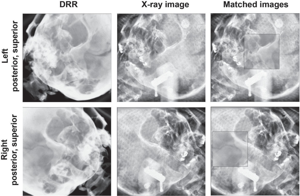
FIGURE 7.12 Example ExacTrac images, DRRs, and matched images for patient position verification.
DRRs, digitally reconstructed radiographs.
Source: From Ma J, Chang Z, Wang Z, et al. ExacTrac X-ray 6 degree-of-freedom image-guidance for intracranial non-invasive stereotactic radiotherapy: comparison with kilo-voltage cone-beam CT. Radiother Oncol. 2009;93(3):602–608. doi: 10.1016/j.radonc.2009.09.009. Reproduced with permission.
AlignRT (Vision RT) has three ceiling-mounted pods with two stereoscopic cameras each that detect an optical speckle pattern that is projected onto the patient’s surface. The deformations in this pattern are used to reconstruct the real-time surface of the patient. This surface is then rigidly registered to the external contour of the patient obtained from the planning CT and the three translations and three rotations necessary to best align the two are displayed. This capability extends to any couch angle. For SRS, this system monitors the patient’s facial topography during treatment to ensure the correct treatment position is maintained throughout the whole fraction (see Figure 7.13). This technique has been successfully used for frameless SRS treatments with comparable clinical outcomes to conventional framed and frameless techniques (89–91). This equipment is also commercialized by Varian under the name of OSMS. Although external surface might not serve as an adequate surrogate for tumor position for SBRT treatments, surface imaging is still a valuable tool to aid in patient setup and monitoring. Another option commercially available for surface imaging is Catalyst (C-Rad AB, Sweden). This system comes with one and three camera installations, depending on the Catalyst model. It uses near-invisible violet light to scan the surface of the patient, and it performs nonrigid registration to obtain the translations and rotations needed to achieve overall alignment. The areas that need to be individually adjusted, such as arms, are indicated with a projection of red and yellow lights onto the patient. Although literature on the use of Catalyst for SRS or SBRT is limited, this system has the potential to have the same applicability as AlignRT.
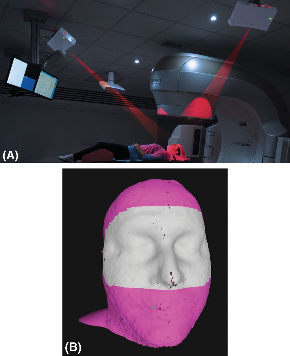
FIGURE 7.13 Elements of frameless SRS with surface imaging: (A) patient in the treatment position with an open mask being monitored with the AlignRT surface imaging system; (B) region of interest shown in gray for open-mask patient tracking.
SRS, stereotactic radiosurgery.
Source: Reproduced with the permission of Vision RT.
PERFORMANCE COMPARISONS
There have been several publications comparing the different delivery systems for SRS/SBRT treatments. This section describes some of the more recent work.
The performance of the CyberKnife, Gamma Knife Perfexion, and Novalis systems was assessed by calculating and comparing the target coverage, CI, GI, and beam-on time with each platform for SRS treatments (92). Ten meningioma patients, originally treated with CyberKnife, were replanned using the Novalis (with IMRT or dynamic conformal arcs, at the discretion of the planner) and Perfexion systems. All of them achieved comparable target coverage but the Gamma Knife and CyberKnife had better CI. Of the three technologies, the Gamma Knife also showed significantly steeper dose falloff gradients, with CyberKnife and Novalis being comparable. Conversely, Gamma Knife had the longest treatment times in the group. Comparisons focusing on Gamma Knife versus linac-based VMAT treatments are also available. Liu et al. performed a planning study on patients with three to four brain metastases comparing the dosimetric 91parameters and treatment efficiency of Gamma Knife Perfexion with single-isocenter noncoplanar RapidArc delivery with a TrueBeam STx (93). Similarly to the aforementioned work, the largest difference between the systems was the much longer treatment time of Gamma Knife (mean beam-on time of 71.6 minutes vs. 6.4 minutes). Dosimetrically, both of them provided clinically acceptable plans with RapidArc showing significantly better CIs and worse GIs (see Figure 7.14). CIs were improved for linac-based SRS in this study versus in the work presented earlier because of the use of noncoplanar RapidArc delivery instead of coplanar IMRT or dynamic conformal arcs.
Gallo et al. investigated the capabilities of several different treatment platforms for spine SBRT delivery through an end-to-end test performed with an anthropomorphic phantom (53). The systems included in this study were TomoTherapy (using TomoEDGE), Vero (with coplanar IMRT beams), TrueBeam (with flattened and FFF, and RapidArc), and CyberKnife (with three fixed circular collimators per plan). Four targets were simulated in the thoracic region, and four in the lumbar. Doses were measured in the phantom using a 0.007-mL ion chamber in the thoracic region and EBT3 Gafchromic film in the lumbar targets. All treatment plans were designed to meet Radiation Therapy Oncology Group (RTOG) 0631 standards, and all ion chamber measurements were within 3.3% of the planned dose. Gamma analysis of the film measurements also showed consistency between planned and delivered dose distributions across all platforms. Although the authors state that plan characteristics were substantially different between systems, they did not elaborate on these. The salient variation in the study was the beam- on delivery time (see Table 7.1). The TrueBeam had the shortest treatment delivery time with FFF beams, whereas CyberKnife took the longest (average of 4.4 minutes vs. 46 minutes).
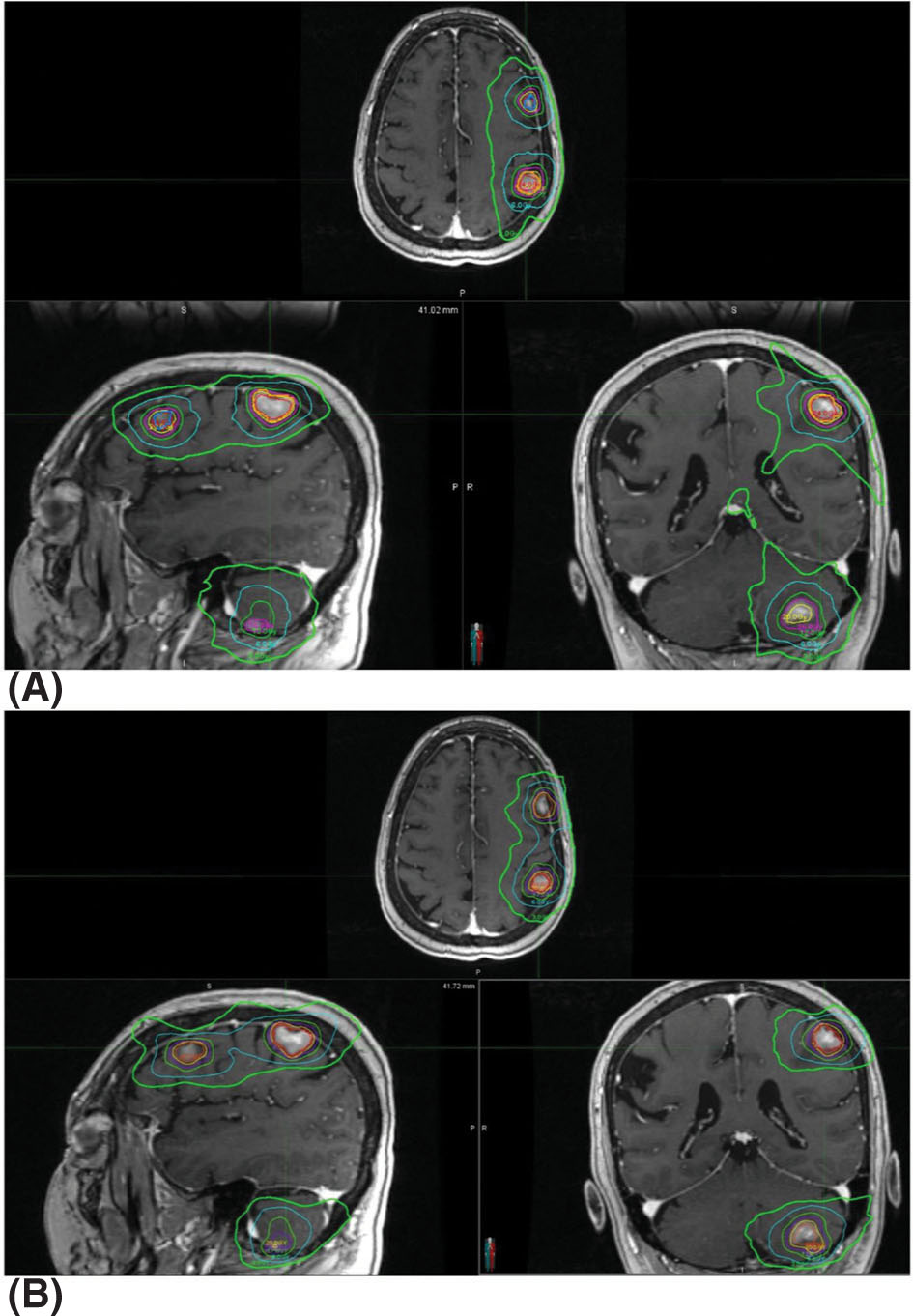
FIGURE 7.14 Isodose distributions of treatment plans for the same patient with (A) single-isocenter VMAT (RapidArc) and (B) Gamma Knife Perfexion. Isodose lines shown are for the 24-, 20-, 16-, 12-, 6-, and 3-Gy lines.
VMAT, volumetric-modulated arc therapy.
Source: From Liu H, Andrews DW, Evans JJ, et al. Plan quality and treatment efficiency for radiosurgery to multiple brain metastases: non-coplanar RapidArc vs. Gamma Knife. Front Oncol. 2016;6:26. doi: 10.3389/fonc.2016.00026
A similar study by Nalichowski et al. published the following year performed the same comparison using the Iris collimator for CyberKnife instead of the fixed collimators and built upon it by describing the differences between the plan characteristics (52). The results showed that, of the four systems investigated, RapidArc and TomoTherapy had higher dose homogeneity in the target, and Vero and CyberKnife displayed lower cord doses and sharper dose falloff, with CyberKnife having the best (see Figure 7.15). Treatment times were much shorter with RapidArc FFF and TomoTherapy than the rest (average 4.4 and 6 minutes, respectively), with CyberKnife taking the longest (average of 58.1 minutes). Therefore, even though recent advances in CyberKnife collimation devices such as the Iris variable aperture collimator or the InCise MLC system have had a great impact on treatment times, these times are still much longer than with other systems. It is important to note that with noncoplanar beam delivery for the TrueBeam and Vero systems, the dose gradient could be improved.
Studies investigating differences between systems for SBRT treatments affected by internal organ motion have been reported in the literature. These include planning studies that investigated the difference between conventional and robotic-based linacs for SBRT lung treatments (94, 95). The authors examined not only the effects of the use of delivery platform but also how respiratory motion is handled (Synchrony for CyberKnife, 4D CT for conventional linacs) by the different platforms. Their results show similar target coverage and critical organ sparing for both systems, but with higher treatment delivery efficiency by conventional linacs (94, 95). However, because of the inherent limitations of planning studies, the effects of tumor motion on the dose distribution with Synchrony tracking versus 4D CT can only be inferred, not measured, from assumptions of the accuracy and reliability of the two methods. A different approach was taken to compare the performance between CyberKnife and Vero for liver SBRT treatments using their respective tracking methods. The study published by Sothmann et al. in 2016 used a two-dimensional (2D) detector array mounted on a 4D platform to measure the delivery differences, on the basis of 1%/1-mm gamma analysis, with respect to predicted versus actual tumor trajectories, and the effects of baseline drifts (96). Both systems performed well but the CyberKnife dose delivery to the clinical target volume (CTV) was more sensitive to baseline drift. This was attributed to the more infrequent motion model updates for CyberKnife than for Vero. Because treatment times with CyberKnife systems have been reported to be longer than with other systems, their sensitivity to baseline drift could become an important factor for treatment quality.
92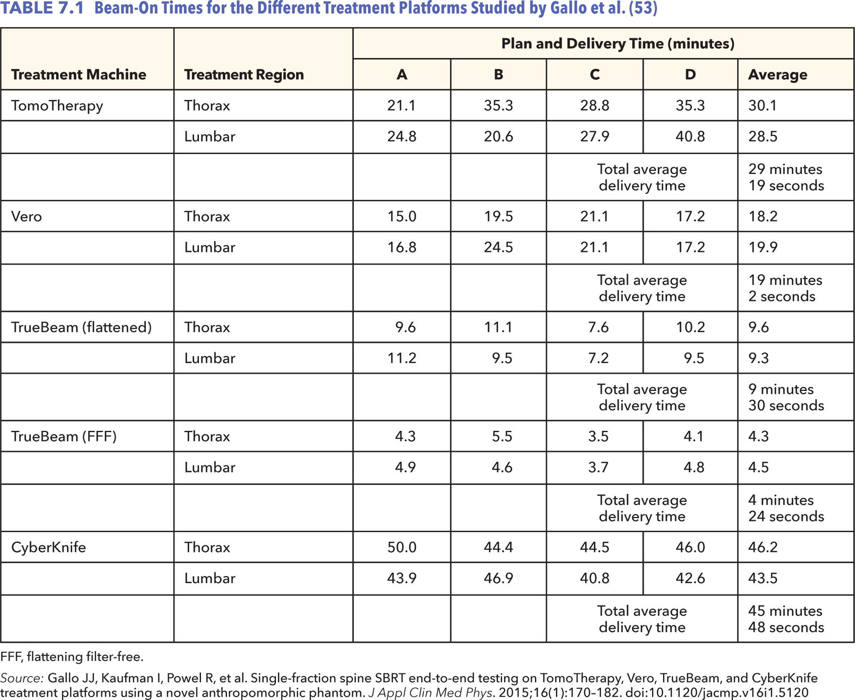
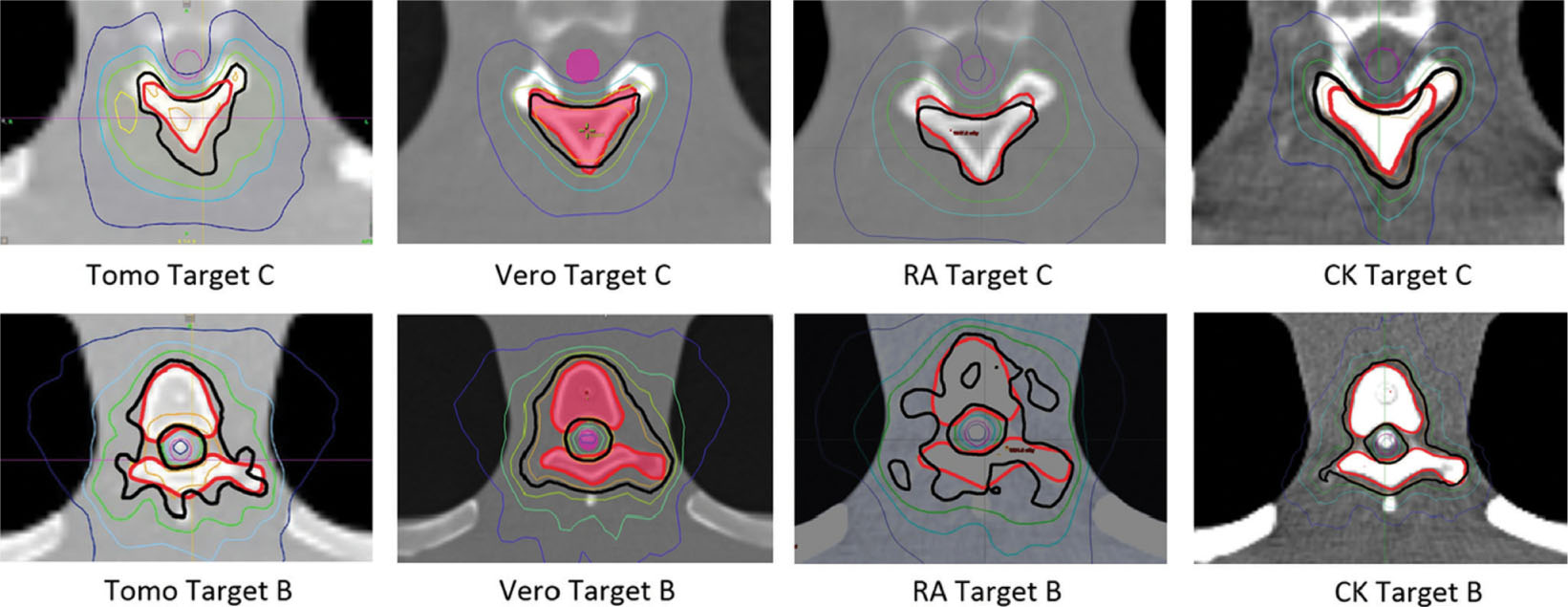
FIGURE 7.15 Isodose distributions for two targets with the spinal cord shown in purple. The isodose lines shown represent the 16.8 Gy in orange, 16 Gy in black, 14.4 Gy in green, 12 Gy in light blue, and 8 Gy in dark blue.
Source: From Nalichowski A, Kaufman I, Gallo J, et al. Single fraction radiosurgery/stereotactic body radiation therapy (SBRT) for spine metastasis: a dosimetric comparison of multiple delivery platforms. J Appl Clin Med Phys. 2017;18(1):164–169. doi:10.1002/acm2.12022
93Just from this brief literature review, it is evident that the performance of a delivery system, such as quality of treatment, beam characteristics, and beam-on time, are impacted not only by the type of machine used for RT but also by the choice of techniques used for a given treatment and accessories used for a given system.
Future Technology
Developments of new SRS/SBRT delivery systems are focused on image guidance improvements. When delivering high doses in one to five fractions, it is very important to be able to clearly visualize the target for optimal alignment during setup and ideally during delivery for real-time tracking. MRI has better soft-tissue contrast than CT. The improved image quality can allow for better localization and tracking of soft-tissue tumors surrounded by critical organs of similar density. The challenge of integrating MRI guidance with linac-based treatment units is the mutual interaction effects between the magnetic field of the imager and the radiofrequency (RF) signal from the electron accelerating system of the linac. There are also concerns regarding the interplay of the magnetic field on the dose distribution because of its possible influence on secondary electrons.
As a result of these difficulties, some institutions have opted for a treatment suite equipped with a diagnostic-grade MR scanner on-rails (97). The treatment couch in this design is modified to move the patient 3.1 m away from isocenter for MR scanning. Once the images have been acquired, the MR scanner is retracted into its shielded area and the couch is moved back to isocenter. These images can then be used analogous to how the CBCT images are used. Although this setup allows for MR imaging with current linac technologies, it requires moving the patient back and forth and it cannot be used for tumor tracking during treatment. There are other options, both clinically available and currently under development, which truly integrate MRI into the treatment system.
There have been ongoing efforts to develop a MR–linac system. Despite the difficulty of combining the two technologies, great progress has already been made. ViewRay MR–linac with 0.35-T MRI system has already been cleared for clinical use by the Food and Drug Administration (FDA) and one other from Elekta is pending approval (98, 99). Elekta MR–linac is designed with higher magnetic field strengths (1–1.5 T) compared with the ViewRay, to achieve diagnostic quality images with which to guide treatment. MR–linacs are designed to still have the capabilities to meet current treatment delivery standards with rotating gantries and MLC for field shaping. There are currently concerns on the effects of the higher magnetic field strengths on secondary electrons and how that could affect dosimetry.
It is also worth noting that 4pi delivery treatments with existing linac systems are also currently being investigated. These treatments would deliver radiation through the simultaneous rotation of gantry and couch. This has been shown to yield more conformal dose distributions and better organ sparing (100–103). Although this is not a new technology, rather enabling current systems to achieve their full potential, it shows improvements in dose delivery distributions when compared with current standards.
PROTONS
The rationale for using proton beams is the feasibility of delivering higher doses to the tumor while substantially reducing the total dose to critical structures. This physical characteristic of proton beams—their finite range—offers some theoretical advantages over clinical photon beams that can be 94used in both single-fraction and hypofractionated dose delivery regimens.
The use of proton and heavier charged particle beams for cancer treatment was promoted almost 70 years ago, when Wilson wrote his seminal paper (104). He pointed out that the fundamental difference in beam penetration of proton and heavy charged particles in tissue, in comparison with photons, can be exploited to achieve normal tissue sparing both proximal and distal to the tumor. The first proton patient was treated in 1954 at Lawrence Berkeley National Laboratory (LBNL) and protons were routinely used as an SRS tool at Harvard Cyclotron Laboratory (HCL) in the 1960s (105). Ions heavier than a proton were first used for cancer therapy in the 1970s when Tobias et al. (106) pointed out that reduced lateral scattering of heavier ions compared with that of protons has the distinct advantage of sharper lateral dose gradients, which are ideal for single-fraction and hypofractionated RT.
The use of protons and heavier charged particle beams waned with the advent of computerized linacs because it is very easy to transform a linac to an SRS or SBRT tool with minor modifications/additions that include the following: better immobilization (rigid or nonrigid) of the patient during imaging and therapy, improved mechanical accuracy of the linac, special collimation, and acquisition of special treatment planning software. Because the majority of radiation oncology departments already have linacs that can be adapted to deliver SRS or SBRT, they have become the most widely used and cost-effective technologies for these modalities.
Technical Considerations of Single-Fraction and Hypofractionated Treatments With Protons
Sharper dose falloff both distally and laterally between the targets and surrounding normal tissues is essential for single-fraction and hypofractionated regimens to succeed. Even though the physics of heavy charged particle interactions with tissue theoretically offers superior solutions to achieve this goal compared with photons, it can be challenging in real clinical situations. The precision and accuracy of both the treatment planning and the delivery of proton therapy are greatly influenced by random and systematic uncertainties associated with the delineation of volumes of interest in 3D imaging, imaging artifacts, tissue heterogeneities, patient immobilization and setup, interfractional and intrafractional patient and organ motion, physiological changes, and treatment delivery. Furthermore, the locations, shapes, and sizes of diseased tissue can change significantly because of daily positioning uncertainties and anatomical changes during the course of radiation treatments. Transient intrafractional changes, such as rectal and bladder filling status, in the treatment of prostate cancer can also introduce uncertainties in dose delivery. Because of these changes, the 3D CT images used for radiation treatment planning do not necessarily correspond to the actual position of the anatomy at the delivery time of each treatment fraction or even to the mean treatment position. Therefore, the traditional assumption that the anatomy discerned from 3D CT images acquired for planning purposes is applicable for every fraction is treated with much reservation in proton therapy.
Range uncertainties, which are attributed to inherent uncertainties in linear stopping power uncertainties, in the formation of broad clinical beams and range degradation in patients can have a profound effect on dose falloff both laterally and distally. The factors that contribute toward range degradation in clinical charged particle beams include patient alignment and setup in treatment beams and relative motion of internal structures with respect to the target volume. Furthermore, the influence of and compensation for heterogeneities on dose distribution is far more critical for protons than for photons. Heterogeneities alter the penetration and lateral scattering of charged particles in the patient. The dosimetric impacts of these two effects in the presence of heterogeneities in proton beams, relative to what occurs in a homogeneous medium, can potentially be substantial because of the sharp dose falloff characteristics of charged particles. Finally, CT imaging remains the de facto standard in RT treatment planning. It provides a spatially accurate map of a patient’s anatomy together with quantitative tissue measurements. Unfortunately, the theoretical relationship between protons’ relative-linear stopping powers (RLSP) and CT Hounsfield unit (HU) numbers is complicated and difficult to evaluate analytically with clinically acceptable accuracy. ICRU Report 78 notes that the overall accuracy of the conversion from HU number to water-equivalent density is of the order of 2% to 4% (1 standard deviation) (107).
Desired Proton Beam Characteristics for Single-Fraction and Hypofractionated Treatments
The most essential characteristic of proton beams for SRS and SBRT is sharp dose falloff both distally and laterally, which is determined largely by 95the quality of the individual pencil beam. The dose distribution of the pencil beam is essentially a Bragg peak longitudinally and Gaussian transversely. The width of the Bragg peak is representative of the energy spread of the protons that affects the distal falloff, whereas the sigma (σ) of the Gaussian gives the spot size of the beam and affects the lateral falloff. Ideally, both of these quantities would have to be minimized to get optimal proton beam characteristic for SRS and SBRT. Paganetti (108) points out that the lateral dose falloff to 50% of the prescribed dose is approximately 0.85σ. Therefore, a desirable σ of clinical proton beam is of the order of 3 mm.
Patient Selection for Single-Fraction and Hypofractionated Treatments With Proton Beams
Although protons allow for the control of dose deposition along and laterally across the beam, the potential of dose uncertainties in proton therapy can be quite large. Therefore, use of proton beams for single-fraction and hypofractionated treatments should be limited to those patients who would potentially benefit from this modality. Proton therapy is an ideal option for patients whose dose to normal tissue and/or organs at risk that surround the target volume poses a problem. Examples include spinal cord irradiation in pediatric patients and skull-based tumors that are close to sensitive normal tissues, such as the brainstem and optical chiasm. On the contrary, proton therapy is not optimal if there are large heterogeneities in the beam’s path, great potential for uncertainties in patient positioning and intrafractional internal organ motion, or significant possibility of physiological changes throughout treatment. Therefore, all potential candidates for proton therapy must be carefully screened and evaluated using relevant imaging studies that establish the clinical appropriateness of this treatment modality.
Summary
The rationale for the use of proton beams in SRS and SBRT, which is based on their ability to provide uniform dose to the target while substantially sparing the dose to normal tissues, is very compelling. This rationale is simply a consequence of the physical characteristics of energy loss by protons as they penetrate into matter. Protons have a finite depth of penetration in material; the magnitude of this penetration depends on the protons’ energy and the density of the irradiated material. This distinct advantage can turn into a double-edged sword if adequate consideration is not given to the potential sources of uncertainties in proton therapy. One must recognize that uncertainties are an inevitable part of the planning and delivery of any RT technique. In this regard, protons are no different from RT delivered with photons; however, the impact of these uncertainties is much more profound in proton therapy. For example, patient-positioning error, patient motion, misalignment of beam modifiers, changes in tissue characteristics, and dosimetric errors in planning and delivery can result in a dose that is very different from what is planned for the patient. Therefore, a comprehensive analysis of potential sources of uncertainty for each patient should be made by evaluating their 3D/4D imaging data and clinical disposition before they are considered for treatment with proton therapy.
CONCLUSIONS
Several different treatment delivery systems for SRS and SBRT have been presented here. Table 7.2 summarizes their characteristics. Although this chapter does not encompass all the systems currently in the market, it provides the reader with a thorough overview of the more commonly available options, future developments, and ancillary equipment used for setup and monitoring of the patient. As seen throughout the text, each platform has its unique characteristics, but all with the common goal of delivering highly accurate and precise treatments through tight mechanical tolerances, stable outputs, and image guidance. This chapter shows that no one treatment platform has all the ideal characteristics; when several options are available for treatment, a decision on the basis of the relative importance of factors such as treatment time length versus dose gradient for the patient in question has to be made.
It is also important to note that although a good delivery system is a very crucial part of ensuring the success of SRS/SBRT treatments, it is only one step in the chain. Understanding the intricacies and challenges of small-field dosimetry during machine commissioning is one of the most important factors for accurate dose calculations. A successful SRS/SBRT program will also need reliable and well-thought-out protocols, careful patient selection on the basis of the technology available for treatment, appropriate treatment planning tools and algorithms, and a well-designed quality management program.
96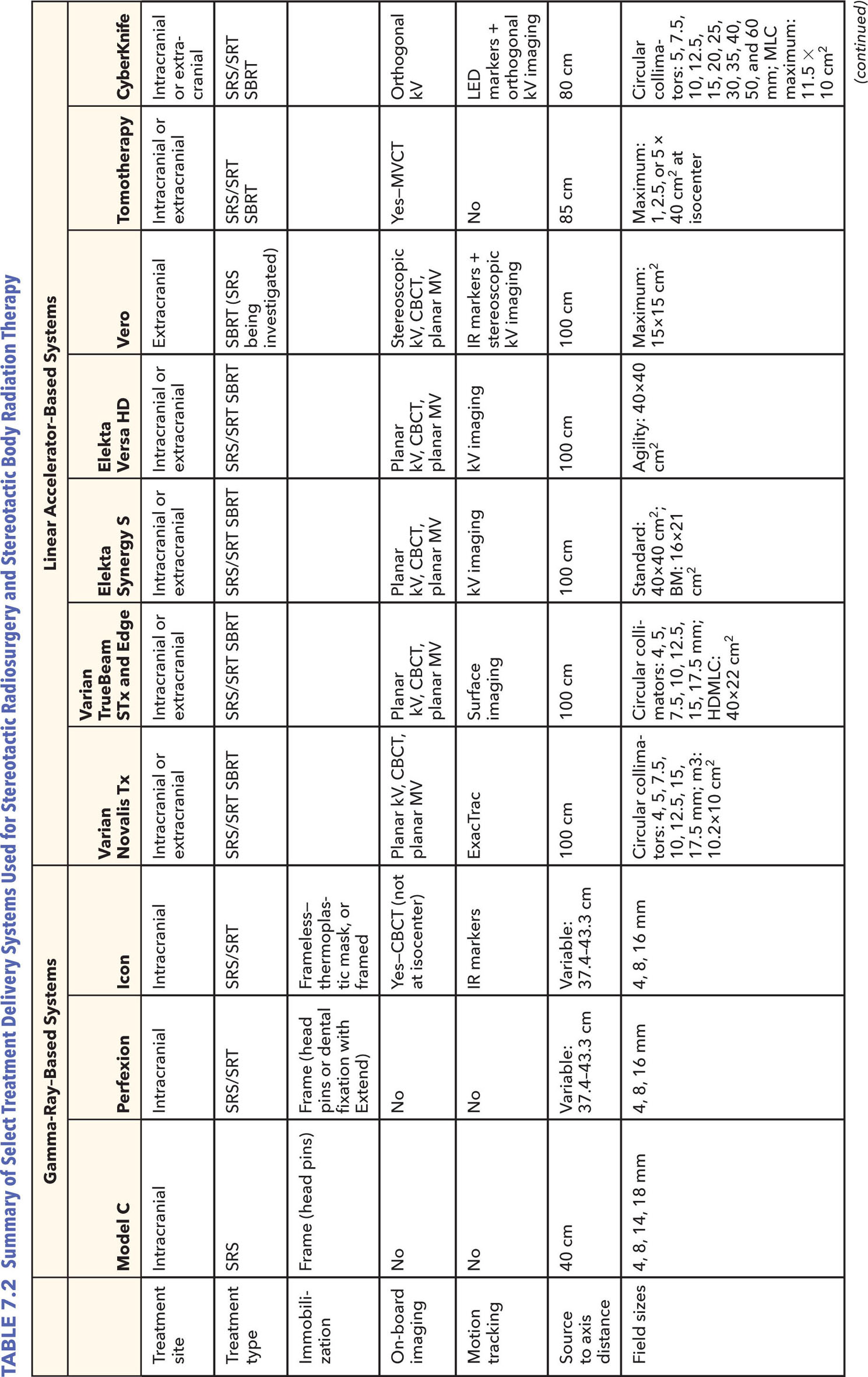
97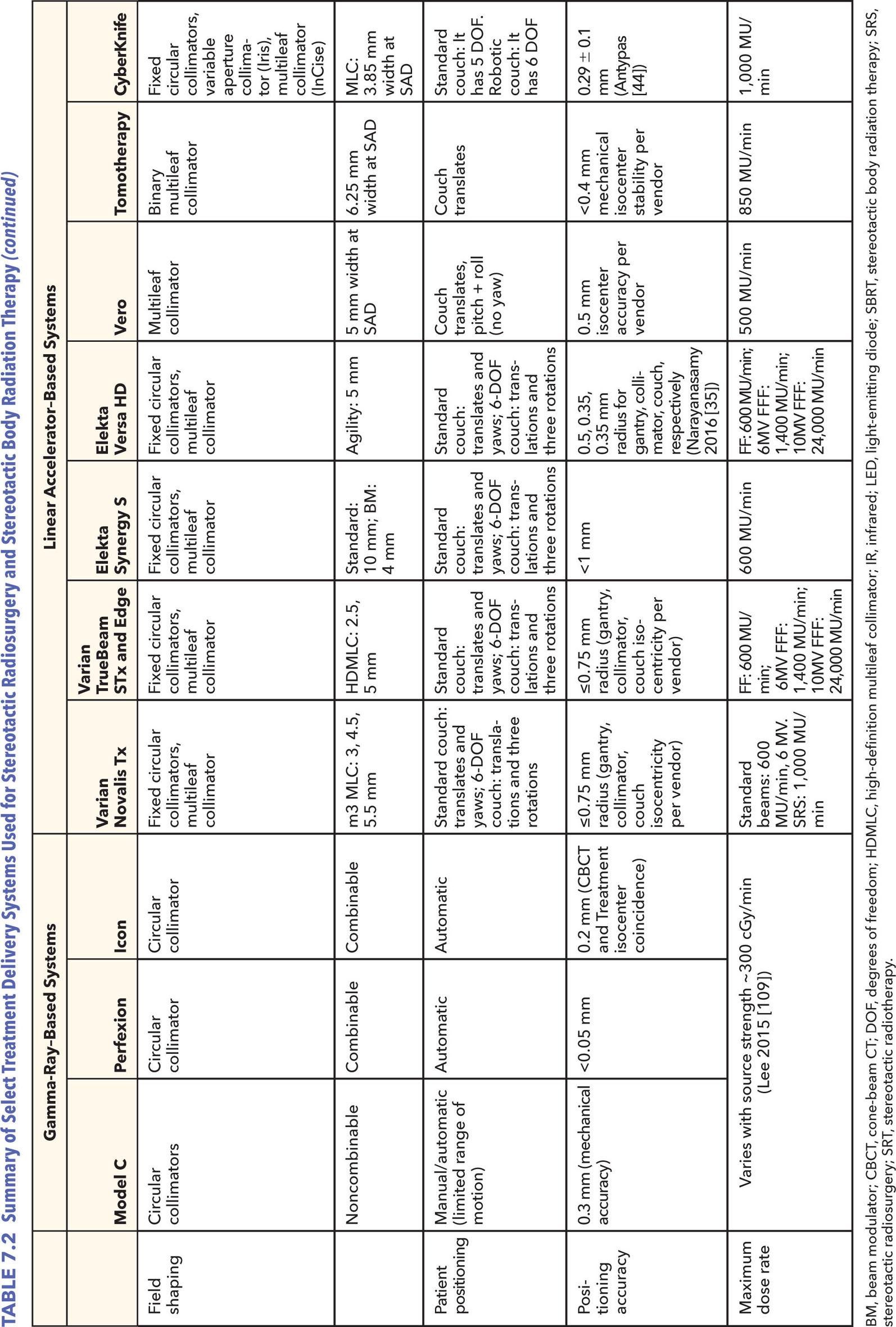
98REFERENCES
1. Solberg TD, Siddon RL, Kavanagh B. Historical development of stereotactic ablative radiotherapy. In: Lo SS, The BS, Lu JJ, et al, eds. Stereotactic Body Radiation Therapy. Berlin, Heidelberg: Springer; 2012:9-35.
2. Benedict SH, Bova FJ, Clark B, et al. Anniversary paper: the role of medical physicists in developing stereotactic radiosurgery. Med Phys. 2008;35(9):4262-4277. doi: 10.1118/1.2969268
3. Goetsch SJ. Risk analysis of Leksell Gamma Knife Model C with automatic positioning system. Int J Radiat Oncol Biol Phys. 2002;52(3):869-877. PubMed PMID: 11849813.
4. Bhatnagar JP, Novotny J, Niranjan A, et al. First year experience with newly developed Leksell Gamma Knife® Perfexion™. J Med Phys. 2009;34(3):141-148. doi: 10.4103/0971-6203.54848
5. Lindquist C, Paddick I. The Leksell Gamma Knife Perfexion and comparisons with its predecessors. Neurosurgery. 2007;61(3 suppl):130-140, discussion. doi: 10.1227/01.neu.0000289726.35330.8a
6. Novotny Jr J, Bhatnagar JP, Xu Y, et al. Long-term stability of the Leksell Gamma Knife® Perfexion™ patient positioning system (PPS). Med Phys. 2014;41(3):031711. doi: 10.1118/1.4866225
7. Schlesinger D, Xu Z, Taylor F, et al. Interfraction and intrafraction performance of the Gamma Knife Extend system for patient positioning and immobilization. J Neurosurg. 2012;117(suppl):217-224. doi:10.3171/2012.6.GKS12989
8. Devriendt D, De Smedt F, Glineur R, et al. Five-fraction Gamma Knife radiosurgery using the Extend relocatable system for benign neoplasms close to optic pathways. Pract Radiat Oncol. 2015;5(3):e119-e125. doi: 10.1016/j.prro.2014.08.021
9. Kim T, Sheehan J, Schlesinger D. Inter- and intrafractional dose uncertainty in hypofractionated Gamma Knife radiosurgery. J Appl Clin Med Phys. 2016;17(2):487-496. doi: 10.1120/jacmp.v17i2.5851
10. Ruschin M, Nayebi N, Carlsson P, et al. Performance of a novel repositioning head frame for gamma knife perfexion and image-guided linac-based intracranial stereotactic radiotherapy. Int J Radiat Oncol Biol Phys. 2010;78(1):306-313. doi: 10.1016/j.ijrobp.2009.11.001
11. Meeks SL, Pukala J, Ramakrishna N, et al. Radiosurgery technology development and use. J Radiosurg SBRT. 2011;1: 21-29. PubMed PMID: 29296294.
12. Zeverino M, Jaccard M, Patin D, et al. Commissioning of the Leksell Gamma Knife® Icon™. Med Phys. 2017;44(2): 355-363. doi: 10.1002/mp.12052
13. Hyperarc: High-definition radiotherapy. Varian Medical Systems; 2016. https://www.varian.com/sites/default/files/resource_attachments/HyperArcBriefOverview_RAD10424_September2016.pdf
14. Sharma SD, Kumar S, Dagaonkar SS, et al. Dosimetric comparison of linear accelerator-based stereotactic radiosurgery systems. J Med Phys. 2007;32(1):18-23. doi: 10.4103/0971-6203.31145
15. Fan J, Paskalev K, Wang L, et al. Determination of output factors for stereotactic radiosurgery beams. Med Phys. 2009;36(11):5292-5300. doi: 10.1118/1.3232217
16. Akimoto M, Nakamura M, Mukumoto N, et al. Baseline correction of a correlation model for improving the prediction accuracy of infrared marker-based dynamic tumor tracking. J Appl Clin Med Phys. 2015;16(2):14-22. doi: 10.1120/jacmp.v16i2.4896
17. Intracranial SRS Package. Varian Medical Systems; 2014. https://www.varian.com/sites/default/files/resource_attachments/SRSProductBrief_RAD10330_April2014_0.pdf
18. Tipton KN, Sullivan N, Bruening W, et al. Stereotactic Body Radiation Therapy [Internet]. Rockville, MD: Agency for Healthcare Research and Quality; 2011. Report No.: 10(11)-EHC058-EF.
19. Marrazzo L, Zani M, Pallotta S, et al. Comparison of stereotactic plans for brain tumors with two different multileaf collimating systems. J Appl Clin Med Phys. 2014;15(1): 27-37. doi: 10.1120/jacmp.v15i1.4100
20. Fischer M, Todorovic M, Drud E, et al. Commissioning of a double-focused micro multileaf collimator (μMLC). J Appl Clin Med Phys. 2010;11(2):81-91. doi: 10.1120/jacmp.v11i2.3131
21. Cosgrove VP, Jahn U, Pfaender M, et al. Commissioning of a micro multi-leaf collimator and planning system for stereotactic radiosurgery. Radiother Oncol. 1999;50(3):325-336. PubMed PMID: 10392819.
22. García-Garduño OA, Celis MA, Lárraga-Gutiérrez JM, et al. Radiation transmission, leakage and beam penumbra measurements of a micro-multileaf collimator using GafChromic EBT film. J Appl Clin Med Phys. 2008;9(3):2802. PubMed PMID: 18716595.
23. Kim J, Wen N, Jin JY, et al. Clinical commissioning and use of the Novalis Tx linear accelerator for SRS and SBRT. J Appl Clin Med Phys. 2012;13(3):124-151. doi: 10.1120/jacmp.v13i3.3729
24. Trilogy System: Powerful Technology at Work in Clinics Around the World Specifications. Varian Medical Systems; 2014.
25. Sharma DS, Dongre PM, Mhatre V, Heigrujam M. Physical and dosimetric characteristic of high-definition multileaf collimator (HDMLC) for SRS and IMRT. J Appl Clin Med Phys. 2011;12(3):3475. PubMed PMID: 21844860.
26. Ouzidane M, Evans J, Djemil T. Dedicated linear accelerators for stereotactic radiation therapy. In: Benedict SH, Schlesinger DJ, Goetsch SJ, et al, eds. Stereotactic Radiosurgery and Stereotactic Body Radiation Therapy. Boca Raton, FL: CRC Press; 2014:67-90.
27. TrueBeam STx System Specifications. Varian Medical Systems; 2015. https://varian.force.com/servlet/servlet.FileDownload?retURL=%2Fapex%2FCpEventPresList%3Fid%3Da0OE000000pZaMdMAK&file=00PE000000VdZ5OMAV
28. Edge Radiosurgery System Specifications. Varian Medical Systems; 2014. https://varian.force.com/servlet/servlet.FileDownload?retURL=%2Fapex%2FCpEventPresList%3Fid%3Da0OE000000pZaMdMAK&file=00PE000000VdYjIMAV
29. Patel I, Glendinning AG, Kirby MC. Dosimetric characteristics of the Elekta Beam Modulator™. Phys Med Biol. 2005;50(23):5479. doi: 10.1088/0031-9155/50/23/004
30. Wang S, Gong Y, Xu Q, et al. Impacts of multileaf collimators leaf width on intensity-modulated radiotherapy planning for nasopharyngeal carcinoma: analysis of two commercial elekta devices. Med Dosim. 2011;36(2):153-159. doi: 10.1016/j.meddos.2010.02.007
31. Podder TK, Bednarz G, Yu Y, et al. Physical characterization and comparison of two commercially available micro-MLCs. Phys Med. 2011;27(1):52-57. doi: 10.1016/j.ejmp.2010.01.005
32. Thompson CM, Weston SJ, Cosgrove VC, et al. A dosimetric characterization of a novel linear accelerator collimator. Med Phys. 2014:41(3):031713. doi: 10.1118/1.4866228
33. Bedford JL, Thomas MDR, Smyth G. Beam modeling and VMAT performance with the agility 160-leaf multileaf collimator. J Appl Clin Med Phys. 2013;14(2):172-185. doi: 10.1120/jacmp.v14i2.4136
34. Fast MF, Nill S, Bedford JL, et al. Dynamic tumor tracking using the Elekta Agility MLC. Med Phys. 2014;41(11):111719. doi: 10.1118/1.4899175
Related posts:

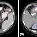
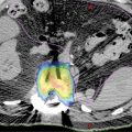
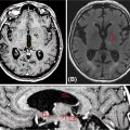
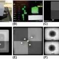

Stay updated, free articles. Join our Telegram channel

Full access? Get Clinical Tree


