Chapter 11 Physical principles of Doppler ultrasound
INTRODUCTION
A Doppler ultrasound is a non-invasive test that can be used to investigate movement and particularly evaluate blood flow in arteries and veins. It can also be used to provide information regarding the perfusion of blood flow in an organ or within an area of interest. A more recent application is the investigation of tissue wall motion when evaluating the heart (see Chapter 14 on New technology).
Doppler ultrasound can be used to diagnose many conditions, including:
THE DOPPLER PRINCIPLE
The Doppler Effect
An everyday example which demonstrates the Doppler effect is highlighted in Figure 11.1. We are all aware that the pitch of an ambulance siren changes as we stop and listen to it as it drives by. The frequency that reaches you is higher as the ambulance approaches and lower as the ambulance passes by. This is a consequence of the Doppler effect.
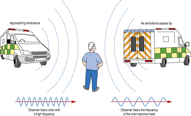
This Doppler effect is utilized in ultrasound applications to detect blood flow by analyzing the relative frequency shifts of the received echoes brought about by the movement of red blood cells.
THE DOPPLER EFFECT APPLIED TO DIAGNOSTIC ULTRASOUND
The transducer acts as both a transmitter and receiver of Doppler ultrasound. When using Doppler to investigate blood flow in the body, the returning backscattered echoes from blood are detected by the transducer. These backscattered signals (Fr) are then processed by the machine to detect any frequency shifts by comparing these signals to the transmitted Doppler signals (Ft). The frequency shift detected will depend on two factors, namely the magnitude and direction of blood flow (see Fig. 11.2).
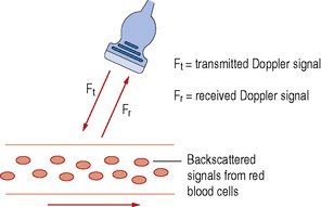
Let us consider a simple arrangement as seen in Figure 11.3. The transducer transmits a Doppler signal with frequency Ft. The transmitted Doppler signal interrogates a blood vessel and the transducer receives the backscattered signals from the red blood cells within the vessel at a frequency Fr. The Doppler frequency shift (Fd) can be calculated by subtracting the transmitted signal Ft from the received signal Fr.
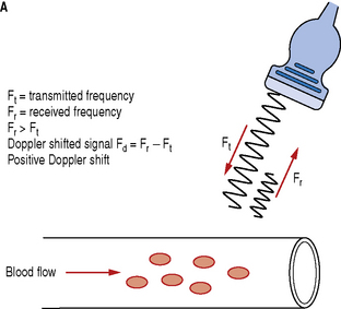
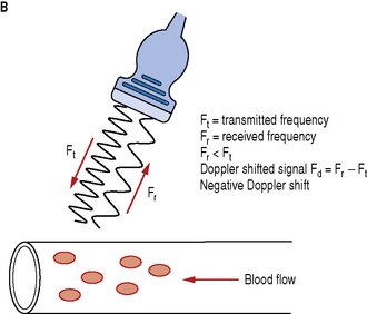
Blood flow moving towards the transducer produces positive Doppler shifted signals and conversely blood flow moving away from the transducer produces negative Doppler shifted signals. Figure 11.3 illustrates the change in the received backscattered signals and the resulting Doppler shifts for blood moving towards and away from the transducer.
In Figure 11.3a the relative direction of the blood flow with respect to the Doppler beam is towards the transducer. In this arrangement blood flow moving towards the transducer produces received signals (Fr) which have a higher frequency than the transmitted beam (Ft). The Doppler shifted signal (Fd) can be calculated by subtracting Ft from Fr and produces a positive Doppler shifted signal.
Conversely, Figure 11.3b illustrates blood flow which is moving away from the Doppler beam and the transducer. In this arrangement blood flow moving away from the transducer produces received signals (Fr) which have a lower frequency than the transmitted beam (Ft). This time the Doppler shifted frequencies (Fr − Ft) produces a negative Doppler shifted signal.
THE DOPPLER EQUATION
Ft = transmitted Doppler frequency
c = the propagation speed of ultrasound in soft tissue (1540 ms−1)
V = velocity of the moving blood
θ = the angle between the Doppler ultrasound beam and the direction of blood flow
Equation 1: The Doppler equation.
Relationship between Doppler Shifted Signal (Fd) and Blood Flow Velocity (V)
The Doppler equation (Equation 1) demonstrates that there is a relationship between the Doppler shifted signal (Fd) and the blood flow velocity (V). The Doppler shifted signal (Fd) is directly proportional to the blood flow velocity (V), which means greater flow velocities create larger Doppler shifted signals and conversely lower flow velocities generate smaller Doppler shifted signals. If we can detect and measure the value of Fd then the Doppler equation can be rearranged (see Equation 2) to calculate blood flow velocities (V) which can be processed and displayed.
Equation 2: Doppler equation rearranged to calculate blood flow velocities (V).
Significance of the Doppler Angle (θ)
Ultrasound machines are able to calculate Doppler shifted frequencies over a wide range of angles and it is important that an operator understands the significance of the angle of insonation (θ) between the Doppler beam and the direction of blood flow in vessels. Figure 11.4 graphically shows how the Doppler shifted signal changes as the Doppler beam angle changes.
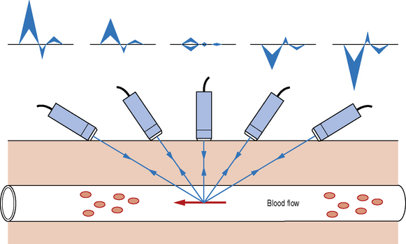
Table 11.1 shows the relationship between the angle of the Doppler beam (θ) and the value of cosθ. The value of cosθ varies with the angle from 0 to 1. When θ = 0°, cosθ = 1 and when θ = 90°, cosθ = 0.
Table 11.1 Variation of the value of cosθ over a range of angles of insonation. Maximum value of cosθ corresponds to a Doppler beam angle of 0°.
| ANGLE θ | VALUE OF COSθ |
|---|---|
| 0 | 1 |
| 30 | 0.87 |
| 45 | 0.71 |
| 60 | 0.5 |
| 75 | 0.26 |
| 90 | 0 |
For a constant flow velocity (V), the maximum value of cosθ and therefore the highest value of the Doppler shifted signal (Fd) is at an angle of 0°. This corresponds to a Doppler beam which is parallel with the vessel, which can rarely be achieved in practice.
Typical Doppler Shifted Signals for Blood Flow
Let us calculate a typical Doppler signal frequency for blood moving at 0.5 ms−1 which is illustrated in Figure 11.5. Transmitted frequency (Ft) is 4 MHz, θ = 60° and c (the propagation speed of ultrasound) is assumed constant at 1540 ms−1.
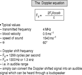
Using the Doppler equation (Equation 1) we calculate the Doppler shifted frequency to be 1299 cycles per second, about 1300 Hz or abbreviated to 1.3 kHz.
TYPES OF DOPPLER INSTRUMENTATION IN DIAGNOSTIC IMAGING
There are a number of types of Doppler instrumentation used in ultrasound which include:
Continuous Wave Doppler Devices
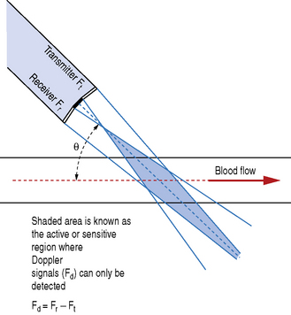
Continuous wave (CW) Doppler devices are the simplest of Doppler instruments and typically consist of a handheld unit with an integrated speaker which is connected to a pencil probe transducer (Fig. 11.6).
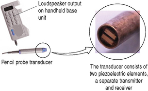
These two elements are set at an angle to each other so that the transmit and reception beams overlap one another, as illustrated in Figure 11.7. This crossover region is known as the active or sensitive area and is where Doppler signals can only be detected. Doppler shift signals (Fd) are detected by comparing the transmitted and received signals: Fd = Fr − Ft.