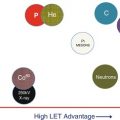
Fig. 5.1
Physical selectivity vs. linear energy transfer (LET) (radiobiological advantage) and cost for different types of beams and techniques (Modified from Raju [2])
While protons are at present rapidly evolving, the use of pions has been already stopped, and neutrons are nearly disappearing, but they provide a full set of data on radiobiology for the use of particles heavier than protons. Several reviews have been published these last years concerning the basis, indications, and the technology in proton therapy [3].
When considering the basic physical interactions of charged particles with matter, we can take into account mainly three “collisions” in the range of energies for clinical applications (up to around 250 MeV for protons):
1.
Nuclear interactions
2.
Inelastic collisions with electrons
3.
Multiple Coulomb scattering by the nucleus
5.2.1 The Nuclear Interactions
The inelastic collisions of the incident protons and heavier ions with the nucleus of the atoms at the target (Fig. 5.2) generate the following as secondary particles and with some associated consequences.

Fig. 5.2
Nuclear interactions through inelastic collisions between an incident charged particle and a nucleus in the range of energies used for clinics (e.g., up to 250 MeV with protons), producing secondary particles and activation
(a)
Neutrons (that will add secondary dose to patients and will be at the origin of large shielding in the accelerator, beam transport components, and treatment rooms)
(b)
Fragments (that will create a “tail” of dose in depth with high biological effects)
(c)
Scattered protons at large angles (increasing the lateral penumbra of clinical beams)
(d)
Activation of accelerators, beam lines, and devices (affecting servicing and decommissioning) as well as tissues in the patient (leading to methods for in vivo dosimetry and/or range verification based on PET measurements or gamma prompt detection)
As a consequence of these nuclear interactions, the number of incident particles is reduced when entering a matter (e.g., the patient). A typical value is a reduction in the flux of particles of 1 % per cm of water equivalent tissues (Fig. 5.3).

Fig. 5.3
Particle flux reduction in depth in tissues from nuclear interactions of incident accelerated protons. At the end of the initial slope, all the remaining particles have lost enough energy with interactions with the electrons to stop at a given range. The variations in the individual ranges give the final slope for what is called “range straggling”
5.2.2 The Inelastic Collisions with Electrons: The Dose and the Bragg Peak
The collisions of the incident protons with the electrons of the matter produce ionization and excitation (Fig. 5.4) and thereby what is of interest in clinical applications: the energy deposition reported to a volume, defined as the dose.

Fig. 5.4
Variation of stopping power with depth. At the entrance of a body, the particles have higher energies, so a (fast) particle spent less time (t) close to the electrons than at the end of the range, when the energy and the speed are lower and the interaction time (T) is longer. In consequence, the “stopping power” is higher at the end of the range, and a larger number of ionizations are produced
When analyzing the particle trajectories in a media such as the tissues, it is of the highest interest to evaluate the stopping power (S = dE/dx), the amount of energy released per unit of length.
The mathematical expression of the stopping power has a dependence on the inverse of the speed of the particle squared, what in practice means is that it increases when the speed decreases, creating its maximum at the end of the range of particle.
As a combination of the decrease in the number of particles in depth in the tissues and the increase of the stopping power also with depth, the deposited dose has an entrance plateau followed by a peak (called the Bragg peak). After the peak, there is a sharp descending gradient till no dose is delivered in the tissues (Fig. 5.5). The depth of this peak can be increased by increasing the energy of the incident particle.

Fig. 5.5
The Bragg peak in the depth dose curve (in yellow) in water for a high-energy proton beam (around 200 MeV). The shape is a combination of the number of particles (in white) and the stopping power (in red). Y-axis is the fraction of the maximum value of the quantity plotted
Indeed, all charged particles, from electrons to heavy ions (both used for clinical applications), have a Bragg peak but with some different final appearance. For electrons, the scattering of particles hides the peak. For heavier ions, the nuclear interactions create a “tail” after the peak (Fig. 5.6a).

Fig. 5.6
(a) Bragg peak for a carbon beam, showing the fractionation tail after the peak (Extracted from M. Moyers, PTCOG meeting 2008); (b) superposition of Bragg peaks of proton beams with different energies to build a spread out Bragg peak (SOBP) covering a target with a given thickness in depth (Modified from H. Kooy, personal communication, 2013)
For all the particles heavier than electrons, it is necessary in clinics to increase the region covered by the peak in the target with a weighted superposition of peaks of different energies (Fig. 5.6b). The resulting dose distribution is called a “spread out Bragg peak” or SOBP. A flat dose is obtained at the target, with the negative consequence of increasing the entrance dose.
The additional interest for heavier particles comes from the biological effect related to the high density of ionization in their track and the possibility to produce a differential effect on tumor and healthy tissues.
5.2.3 The Multiple Coulomb Scattering
The elastic scatter of the incident protons by the nucleus cumulates small deviations of the incident particle when traversing matter (Fig. 5.7). This effect is used with scattering foils of high atomic number (e.g., lead) to build “passive lines.” But it also increases the lateral penumbra for both passive and pencil beam scanned beams in tissue. At depths in tissues larger than 20 cm, the penumbra is larger for a proton beam than for a 6–8 MV photon beam as those used for conformal IMRT with fixed or rotational beams.

Fig. 5.7
Effect of multiple Coulomb scattering by the nucleus. (a) The deviation of the incident particles can be used to build “passive lines” by increasing the initial small Gaussian beam size with simple or double scattering systems. (b) The mushroom shape of a pencil beam, given by the multiple scatter, will be scanned to cover a given target. (c) Final lateral penumbra (20–80 % on lateral profiles) vs. depth in tissue for protons and heavier ions compared to photon beams used in radiation therapy. Mixed graphs (Courtesy from T. Lomax, PSI, N. Schreuder, and own figures)
5.3 Technology and Logistics to Plan and Deliver Proton Therapy
5.3.1 The Beam Characteristics and the Treatment Planning System
From the physical basis described previously, different treatment planning systems have been developed [4]. When simulating a single modulated beam, it is possible to evaluate the advantages and limits of proton beams compared to photon beams, which are traditionally used in clinical applications (Fig. 5.8):

Fig. 5.8
Some advantages (in green circles) and limits (in red) of a single beam of energy modulated protons (spread out Bragg peak) (at the right), compared to a single photon beam (at the left) incidents on an intracranial target at the base of the skull. (SOBP: courtesy of N. Schreuder, Software: Eclipse, Data: IBA, calculations: A. Mazal)
A proton beam has the advantages of a flat entrance plateau (without a maximum in the beam path), a flat homogeneous dose at the target, a high gradient after the target, and, mainly, no dose after the target.
But it has limits such as the high entrance dose, the neutron dose around the target, the uncertainty in the range, and the increased lateral penumbra in depth.
In general, several beam directions are adopted (Fig. 5.9), each one with an optimized range, modulation, and compensation (or equivalent dynamic approaches).

Fig. 5.9
Combination of different incidences of proton beams in anatomical regions with complex inhomogeneities. A treatment plan can include combination of photons and protons as well as “patches” where one beam irradiates part of the target and its distal edge superposes the lateral penumbra of a second beam that irradiates the rest of the target (Calcs L. de Marzi. Software Dosisoft)
5.3.2 The Technological Development
The approach to increase the use of protons in radiation therapy could not have been possible without a very strong development in technology of accelerators, beam transport, delivery, and control systems (Fig. 5.10). The first pioneering facilities in the 1960s used to work with very large accelerators [5] originally conceived for research in physics and built mainly by research laboratories in cooperation with specific companies. In the 1990s, the first clinically oriented devices are conceived in more compact models driven by industrial companies. As an example of this evolution, the synchrocyclotron in Orsay, France, with 900 ton of weight for the magnetic circuit, was built initially by Philips in 1958, reshaped by the Nuclear Physics Institute in 1975, adapted for clinics in 1991, and replaced in 2010 by a new, more compact system.

Fig. 5.10
Technical evolution of accelerators and beam transport for proton therapy: (a) 900 T synchrocyclotron from Orsay, devoted to clinical applications since 1991, (b) cyclotron producing 230 MeV protons developed for proton therapy by the industry (Courtesy of IBA), (c) isocentric gantry to transport the beam in any direction around the patient, (d) robotic patient positioning system at Orsay, (e) compact cryogenic accelerator mounted on the gantry for single treatment room approach (Mevion, USA), (f) principle of dielectric wall cells to produce compact linear accelerators [6], and (g) high-intensity laser-based proton acceleration principle [7]
Clinical particle accelerators are completed with beam transport systems toward several treatment rooms with fixed lines (horizontal, vertical, oblique) or isocentric gantries (able to turn the beam around the patients [8]). They can deliver the beam in the required direction toward the patient. For both fixed and gantry lines, there is a beam modifying system called “nozzle” to shape and monitor the beam (Fig. 5.10).
The technical evolution of proton therapy at present goes toward more and more compact machines, mainly based on cryogenics and very high magnetic fields, conceived in their simplest and cheaper approach to provide beam toward a single treatment room. Other solutions are under development based on high gradients of electric fields to produce compact linacs for proton therapy.
More futuristic and still to be economically and clinically proven, at least two axes of the study have been developed:
(a)
The dielectric wall accelerator (DWA), conceived at the Lawrence Livermore Laboratory in USA, using strong isolators and light-based excitation of dielectrics to produce the particle acceleration through “Blumline cells” with expected gradients of 100 MeV/m [6]
(b)
The laser-based proton acceleration, where high-intensity pulses of a laser beam incident on a target produce a mechanical separation of charges and electric fields of TV/m in a very small space [7]
Both approaches still need to be fully developed, and the feasibility of their clinical use has still not been attained.
5.3.3 The Patient Positioning: Robotics and Imaging
The planning and delivery of a high precision dose distribution with particles or photons would not be possible without a corresponding image-guided system. The roots of such a system are the existing imaging devices as those in use in a diagnostic department (Fig. 5.11). From these original images, there is a phase of calculation and simulation of a treatment by combining multimodalities, setting a segmentation of target and critical organs, and modeling the beams. At the end of this process, imaging systems are also installed and used at the treatment room itself to set up and monitor the patient positioning, giving the required tools to implement adaptive therapy (Fig. 5.12). The imaging system is complemented with the use of robotic approaches for patient positioning [9], providing a full 6D capability with ancillary tools and functions such as multiple supports (couch, chairs, phantoms, detectors), trajectories, compensation of loads, etc.