Imaging systems using ultrasound have attained a large presence as point-of-care (PoC) devices across many clinical domains over the past 10 years. The success of ultrasound for this purpose is attributed to several characteristics, including the low cost and portability of ultrasound devices, the nonionizing nature of ultrasound waves, and the ability to produce real-time images of the acoustic properties of the tissues and tissue structures in the body to deliver timely patient care, among many positive attributes. An understanding of the basic physics of ultrasound, in addition to hands-on training, practice, and development of experience are of great importance in its effective and safe use. This chapter describes the characteristics, properties, and production of ultrasound; interaction with tissues, acquisition, processing, and display of the ultrasound image; the instrumentation; achievable measurements, including blood velocity; and safety issues.
Characteristics of Sound
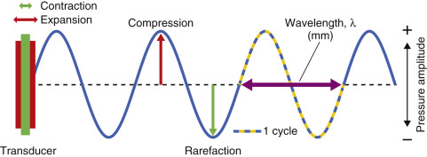
Sound is mechanical energy that propagates through a continuous, elastic medium by the compression (high pressure) and rarefaction (low pressure) of particles that comprise it. Compression is caused by a mechanical inward deformation by an external force, such as an expanding and contracting transducer crystal composed of multiple elements in contact with the medium. During transducer surface expansion, an increase in the local pressure at contact occurs. Contraction of the crystal follows, causing a decrease in pressure. The mechanical energy imparted at the surface is transferred to adjacent particles of the medium, which travels at the speed of sound through the medium. Continuous expansion and contraction of the crystal surface by an external power source introduces energy into the medium as a series of compressions and rarefactions, traveling as a wave front in the direction of travel, known as a longitudinal wave, as shown in Fig. 1.1 .
Wavelength, Frequency, Speed
The wavelength ( λ ) is the distance between any two repeating points on the wave (a cycle), typically measured in millimeters (mm). The frequency ( f ) is the number of times the wave repeats per second (s), also defined in hertz (Hz), where 1 Hz = 1 cycle/s. Frequency identifies the category of sound: less than 15 Hz is infrasound, 15 Hz to 20,000 Hz (20 kHz) is audible sound, and above 20 kHz is ultrasound. Medical ultrasound typically uses frequencies in the million cycles/ s megahertz (MHz) range, from 1 to 15 MHz, with some specialized ultrasound applications beyond 50 MHz. The period is the time duration of one wave cycle and is equal to 1/ f . The speed of sound, c, is the distance traveled per unit time through a medium and is equal to the wavelength (distance) divided by the period (time). As frequency is inversely equal to the period, the product of wavelength and frequency is equal to the speed of sound, c = λ f. The speed of sound varies substantially for different materials, based on compressibility, stiffness, and density characteristics of the medium. For instance, air is highly compressible and of low density, with a relatively low speed of sound; bone is stiff and dense, with a relatively very high speed of sound; and soft tissues have compressibility and density characteristics with intermediate speeds, as listed in Table 1.1 . Of importance are the average speeds for “soft tissue” (1540 m/s), fatty tissue (1450 m/s), and air (330 m/s). To relate time with depth interactions in the patient, medical ultrasound devices assume a speed of sound of 1540 m/s, despite slight differences in actual speed for the various tissues encountered. Changes in the speed of sound can affect how ultrasound travels through the tissues and may result in unexpected artifacts (see Chapter 2 on speed artifact and refraction artifact). The product of the density and speed of sound is known as the acoustic impedance . This characteristic of the tissues is intrinsic in the generation of ultrasound echoes, which return to the transducer to create the ultrasound image. More detail is in the next section on ultrasound interactions.
| Material | Density (kg/m 3 ) | c (m/s) | Z (rayls) ∗ |
|---|---|---|---|
| Air | 1.2 | 330 | 3.96 × 10 2 |
| Lung | 300 | 600 | 1.80 × 10 3 |
| Fat | 924 | 1450 | 1.34 × 10 6 |
| Water | 1000 | 1480 | 1.48 × 10 6 |
| “Soft tissue” | 1050 | 1540 | 1.62 × 10 6 |
| Kidney | 1041 | 1565 | 1.63 × 10 6 |
| Blood | 1058 | 1560 | 1.65 × 10 6 |
| Liver | 1061 | 1555 | 1.65 × 10 6 |
| Muscle | 1068 | 1600 | 1.71 × 10 6 |
| Skull bone | 1912 | 4080 | 7.8 × 10 6 |
| PZT | 7500 | 4000 | 3.0 × 10 7 |
∗ Acoustic impedance is the product of density and speed of sound. The rayl is the named unit, with base units of kg/m 2 /s. Acoustic impedance directly relates to the propagation characteristics of ultrasound in a given medium and between media.
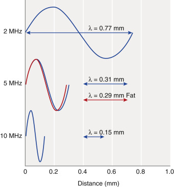
In a homogeneous medium, ultrasound frequency and speed of sound are constant. When higher ultrasound frequency is selected, the wavelength becomes shorter, giving better detail and spatial resolution along the direction of propagation. For instance, in soft tissue with a speed of 1540 m/s, a 5-MHz frequency has a wavelength in tissue of λ = c / f ; 1540 m/s ÷ 5,000,000/s = 0.00031 m = 0.31 mm. A 10-MHz frequency has a wavelength = 0.15 mm ( Fig. 1.2 ). Although higher frequencies provide better resolution, they are also more readily attenuated, and depth penetration can be inadequate for certain examinations, such as for the heart and abdomen.
Intensity
The amount of ultrasound energy imparted to the medium is dependent on the pressure amplitude variations generated by the degree of transducer expansion and contraction, controlled by the transmit gain applied to a transducer. Power is the amount of energy per unit time introduced into the medium, measured in milliwatts (mW). Intensity is the concentration of the power per unit area in the ultrasound beam, typically expressed in mW/cm 2 . Signals used for creating images are derived from ultrasound interactions in the tissues and the returning intensity of the produced echoes. Absolute intensity depends on the method of ultrasound production and can result in heating or mechanical disruption of tissues, as discussed later in this chapter.
Interactions of Ultrasound with Tissues
Interactions of ultrasound are chiefly based on the acoustic impedance of tissues and result in reflection, refraction, scattering, and absorption of the ultrasound energy.
Acoustic Impedance
Acoustic impedance , Z, is a measure of tissue stiffness and flexibility, equal to the product of the density and speed of sound: Z = ρ c , where ρ is the density in kg/m 3 and c is the speed of sound in m/s, with the combined units given the name rayl, where 1 rayl is equal to 1 kg/(m 2 s). Air, soft tissues, and bone represent the typical low, medium, and high ranges of acoustic impedance values encountered in the patient, as listed in Table 1.1 . The efficiency of sound energy transfer from one tissue to another is largely based on the differences in acoustic impedance—if impedances are similar, a large fraction of the incident intensity at the boundary interface will be transmitted, and if the impedances are largely different, most will be reflected. In most soft tissues, these differences are typically small, allowing for ultrasound travel to large depths in the patient.
Reflection
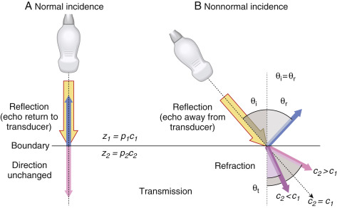
Reflection occurs when a beam is traveling perpendicular (at normal incidence or 90 degrees) to the boundary between two tissues that have a difference in acoustic impedance ( Fig. 1.3A ). The fraction of incident intensity I i reflected back to the transducer (I r ) is the intensity reflection coefficient, R I , calculated as
RI=IrIi=(Z2-Z1Z2+Z1)2
The subscripts 1 and 2 represent tissues that are proximal and distal to the boundary. The intensity transmission coefficient, T I , is defined as the fraction of the incident intensity that is transmitted across an interface, equal to T I = 1 – R I . For a fat–muscle interface, the intensity reflection and transmission coefficients are calculated as
RI,(Fat→Muscle)=IrIi=(1.71−1.341.71+1.34)2=0.015;TI,(Fat→Muscle)=1−RI,(Fat→Muscle)=0.985
A high fraction of ultrasound intensity is transmitted at tissue boundaries for tissues that have similar acoustic impedance. For tissues with large differences of acoustic impedance, such as air-to-tissue or tissue-to-bone boundaries, most of the intensity is reflected, with no further propagation of the ultrasound pulse. At a muscle–air interface, nearly 100% of incident intensity is reflected, making anatomy unobservable beyond an air-filled cavity. Acoustic coupling gel placed between the transducer and the patient’s skin is a critical part of the standard ultrasound imaging procedure to ensure good transducer coupling and to eliminate air pockets that would reflect the ultrasound. For imaging beyond lung structures, avoidance of the ribs and presence of a “tissue conduit” are necessary to achieve propagation of the pulse. When an ultrasound pulse is incident on a tissue boundary at an angle other than 90 degrees (normal incidence), the reflected ultrasound echo is directed away from the transducer and does not generate a signal.
Refraction
Refraction is a change in direction of the transmitted ultrasound pulse when the incident pulse is not perpendicular to the tissue boundary and the speeds of sound in the two tissues are different. The frequency does not change, but the ultrasound wavelength changes at the boundary due to the speed change, resulting in a redirection of the transmitted pulse, as shown in Fig. 1.3B . The angle of redirection is dependent on the change in wavelength; no refraction occurs when the speed of sound is the same in the two tissues or with perpendicular incidence. Because a straight-line propagation of the ultrasound pulse is assumed, misplacement of anatomy can result when refraction occurs. See Chapter 2 on ultrasound artifacts for further discussion and manifestation of this type of artifact.
Scattering
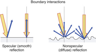
Scattering arises from objects and interfaces within a tissue that are about the size of the ultrasound wavelength or smaller. At low frequencies (1–5 MHz), wavelengths are relatively large, and tissue boundaries appear smooth or specular (mirror-like). A specular reflector is a smooth boundary between two media. At higher frequencies (5–15 MHz), wavelengths are smaller, and boundaries become less smooth, causing echo reflection in many directions. A nonspecular reflector represents a boundary that presents many different angles to the ultrasound beam, and returning echoes have significantly less intensity ( Fig. 1.4 ). Many organs can be identified by a defined “signature” caused by intrinsic structures that produce variations in the returning scatter intensity. Scatter amplitude differences from one tissue region to another result in corresponding brightness changes on the ultrasound display. In general, the echo signal amplitude from a tissue or material depends on the number of scatterers per unit volume, the acoustic impedance differences at interfaces, the sizes of the scatterers, and the ultrasound frequency. Higher scatter amplitude tissues are called hyperechoic, and lower scatter amplitude tissues are called hypoechoic relative to the average background signal. Scattered echo signals are more prevalent relative to specular echo signals when using higher ultrasound frequencies.
Absorption and Attenuation
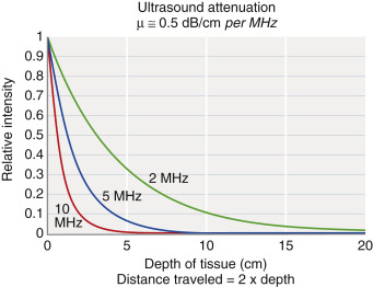
Attenuation is the loss of intensity with distance traveled, caused by scattering and absorption of the incident beam. Scattering has a strong dependence on increasing ultrasound frequency. Absorption occurs by transferring energy to the tissues that result in heating or mechanical disruption of the tissue structure. The combined effects of scattering and absorption result in exponential attenuation of ultrasound intensity with distance travelled as a function of increasing frequency. When expressed in decibels (dB), a logarithmic measure of intensity, attenuation in dB/cm linearly increases with ultrasound frequency. An approximate rule of thumb for ultrasound attenuation average in soft tissue is 0.5 dB/cm times the frequency in MHz. Compared with a 1-MHz beam, a 2-MHz beam will have approximately twice the attenuation, a 5-MHz beam will have five times the attenuation, and a 10-MHz beam will have ten times the attenuation per unit distance traveled . Therefore higher-frequency ultrasound beams have a rapidly diminishing penetration depth ( Fig. 1.5 ), so careful selection of the transducer frequency must be made in the context of the imaging depth needed. The loss of ultrasound intensity in decibels can be determined empirically for different tissues by measuring as a function of distance travelled in centimeters (cm) and is the attenuation coefficient, μ , expressed in dB/cm . For a given ultrasound frequency, tissues and fluids have widely varying attenuation coefficients chiefly resulting from structural and density differences, as indicated in Table 1.2 for a 1-MHz ultrasound beam.
| Tissue | μ (1 MHz) |
|---|---|
| Air | 1.64 |
| Blood | 0.2 |
| Bone | 7–10 |
| Brain | 0.6 |
| Cardiac | 0.52 |
| Connective tissue | 1.57 |
| Fat | 0.48 |
| Liver | 0.5 |
| Muscle | 1.09 |
| Tendon | 4.7 |
| Soft tissue (average) | 0.54 |
| Water | 0.0022 |
∗ For higher-frequency operation, multiply the attenuation coefficient by the frequency in MHz.
The Ultrasound System
PoC ultrasound systems are available from many vendors and come with different features and options, which depend on acquisition capabilities, number of transducer probes, durability, software functionality, size and weight, battery longevity for handheld units, power requirements, and other considerations. Although all ultrasound systems have unique instrumentation, software, and user interfaces, common components include transducer probes, pulser, beam former, scan converter, processor, display, and user interface for instrumentation adjustments and controls.
Ultrasound Transducer Operation and Beam Properties
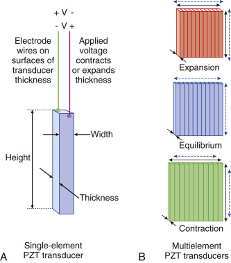
Ultrasound is produced and detected with a transducer array, composed of hundreds of ceramic elements with electromechanical (piezoelectric) properties. Ultrasound transducers for medical imaging applications employ a synthetic piezoelectric ceramic, lead–zirconate–titanate (PZT), with a crystal structure that generates a surface charge of either negative or positive polarity when its thickness is expanded under negative pressure or compressed under positive pressure due to the internal molecular crystal polarity. Surface electrodes and wires are attached to each element and multiplexed to a transmit/receive sensor that measures the surface charge variation when sensing any thickness variations. These same wires and attached electrodes generate mechanical expansion or contraction by applying a voltage of known polarity and amplitude from an external power source, as illustrated in Fig. 1.6A . By varying the applied voltage polarity at a known frequency, the crystal expands and contracts, imparting mechanical energy into the adjacent medium at the same frequency. Thus each transducer element functions either in an excitation mode to transmit ultrasound energy or in a reception mode to receive ultrasound energy. In practice, a subset of elements in a linear transducer array, or all elements in a phased transducer array, are activated, as shown in Fig. 1.6B , to create an ultrasound beam.
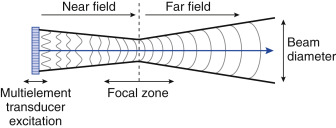
The surface vibration and interaction among the individual elements create a collimated beam converging in the near field with a minimum beam diameter at the focal zone depth and, with further travel, diverging into the far field, as shown in Fig. 1.7 . The focal zone depth can be adjusted by introducing brief timing delays of the individual element arrays, as discussed later.
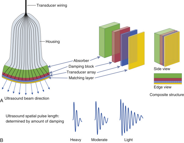
Ultrasound systems have transducer assemblies of many shapes and sizes composed of an array of PZT elements (typically 64–512) categorized into linear and phased array operation. Common to all transducers are a protective housing with a shield to prevent electrical interference, an acoustic damping block to shorten the vibrations of the piezoelectric elements, a matching layer to improve the efficiency of ultrasound wave transmission to the skin by reducing acoustic impedance differences, and a material to absorb backward-directed ultrasound energy ( Fig. 1.8A ).
Related posts:


Stay updated, free articles. Join our Telegram channel

Full access? Get Clinical Tree


