A. Emulsions
–Analog radiography uses film to capture, display, and store radiographic images.
–Film consists of an ~10-μm-thick emulsion supported by a 150-to 200-μm-thick polyester (Mylar) base.
–Most radiographic films have an emulsion layer on both sides of the base.
–Laser and mammography films are exceptions and have a single emulsion.
–Additional layers on radiographic film can include a protective coating, antistatic, or anti-crossover layer.
–The emulsion contains silver halide (iodobromide) grains, which can be sensitized by radiation or light to hold a latent image.
–Silver halide grains are typically about 1 μm in diameter and contain between 106 and 107 silver atoms.
–There are about 109grains per cubic centimeter.
–Several light photons must be absorbed to sensitize each grain.
–A grain may also be sensitized by absorbing a single x-ray photon.
–Absorbed light photons liberate electrons in the grain, which combine with positively charged silver ions (Ag+) to produce electrically neutral atoms of silver.
–Grains that have been sensitized by absorption of light or x-rays form the latent image. Silver halide grains can also be sensitized by thermal and chemical processes without photons (i.e., fogging).
–Sensitized grains are relatively stable, but can fade over time.
–Fading and fogging can be aggravated by environmental heat and humidity.
B. Film development
–After exposure, grains have a few neutral silver atoms in the speck along with millions of Ag+ ions.
–The film development process converts the invisible latent image to a permanent visible image.
–Sensitized grains are reduced in the alkaline developer solution by the addition of electrons, which converts the positive silver ions to silver atoms.
–A developed grain results in a speck of silver that appears black on the film.
–Unexposed grains with no latent image are developed at a much slower rate.
–Film speed, contrast, and fog levels are all affected by developer chemistry and temperature.
–Increasing the developer temperature can increase film contrast and density.
–Increasing development time has a similar effect to using higher developer temperature.
–Raising the developer temperature also increases the level of fogging on the processed film.
C. Film processors
–Modern film processors automatically run film sequentially through the developer, fixer, and washing solutions using a series of rollers to transport the film.
–Developer temperatures typically range from 31◦C to 35◦C.
–The developer is consumed during the reduction of the sensitized silver halide grains.
–The processor must supply fresh developer as more films are run (replenishment).
–The rate of replenishment depends on the workload of the processor.
–The fixing solution contains acetic acid to inhibit further development and remove unexposed silver halide grains.
–Fixing makes the image stable.
–Inadequate fixation can result in a milky appearance to the film.
–After fixing, the film is washed again to eliminate all chemicals and is then dried by heaters or infrared lamps.
–Incomplete removal of the fixer causes the film to turn brown.
–The total processing time is typically 90 seconds (e.g., 25 seconds developer time, 21 seconds fixer time, 44 seconds washing and drying time).
–Dirty, uneven, or maladjusted rollers can leave lines or other artifacts (e.g., π lines) on the film.
–Static electricity also causes severe film artifacts.
–Film processor quality control (QC) is essential in maintaining film image quality at a high level.
–Processor QC involves measuring developer temperature and monitoring the density and contrast of film exposed to a light source in a sensitometer.
D. Film density
–After processing, the blackening of the film represents the pattern of x-rays reaching the cassette.
–Film blackening is related to the number of x-ray or light photons that exposed the film.
–Film blackening is measured using optical density (OD).
–OD = log10(I0/It), where I0 is the light intensity incident on the film, and It is the light transmitted through the film.
–OD can be measured using a densitometer.
–Transmittance is the fraction of incident light passing through the film, where the transmittance = It/I0.
–As OD increases, transmittance decreases.
–The useful range of film ODs is from ~0.3 (50% transmittance) to ~2 (1% transmittance).
–Densities greater than about 2 require the use of a hot (bright) light.
–The OD of superimposed films is additive, so two films with an OD of 1.0 (10% transmittance) superimposed would have an OD of 2.0 and transmit 1% of the incident light.
–Table 3.1 shows the relationship between optical density and transmittance.
E. Characteristic curves
–The characteristic curve represents the relation between radiation intensity (air kerma) and resultant film optical density as shown in Figure 3.1.
–Characteristic curves are also known as H and D curves, named after Hurter and Driffield who first generated such a curve (1890).
–The toe is the low-exposure region, and the shoulder is the high-exposure region of the curve.
–Fog is the level of blackening due to a few grains being developed in the absence of any radiation exposure.
–Base refers to the density of the film base alone, which will absorb a small faction of any incident light.
–Base plus fog levels are ~0.2 OD units.
–An unexposed film that is processed will thus have a film density of ~0.2.
TABLE 3.1 Relationship between Light Transmittance and Film Optical Density
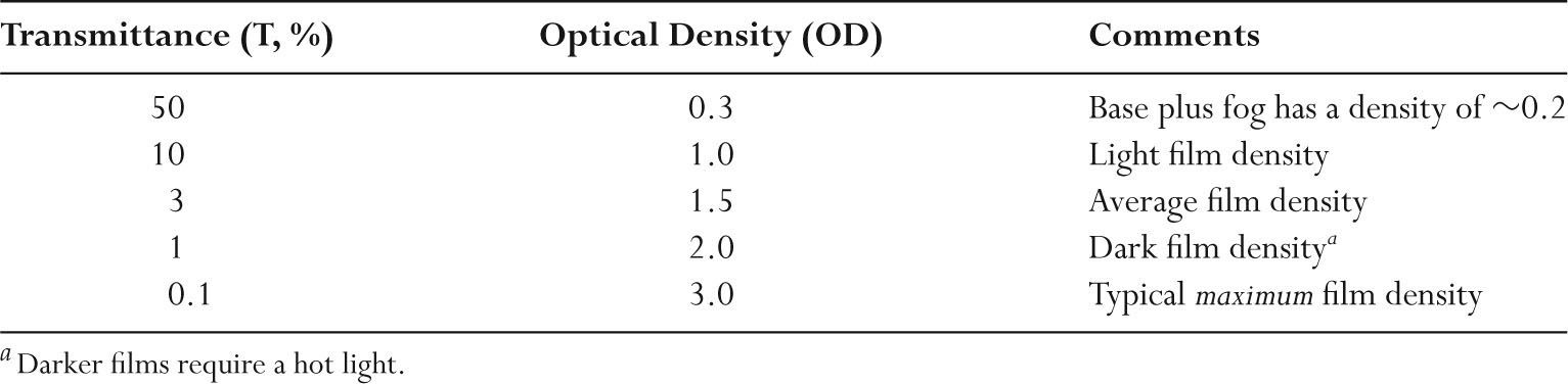
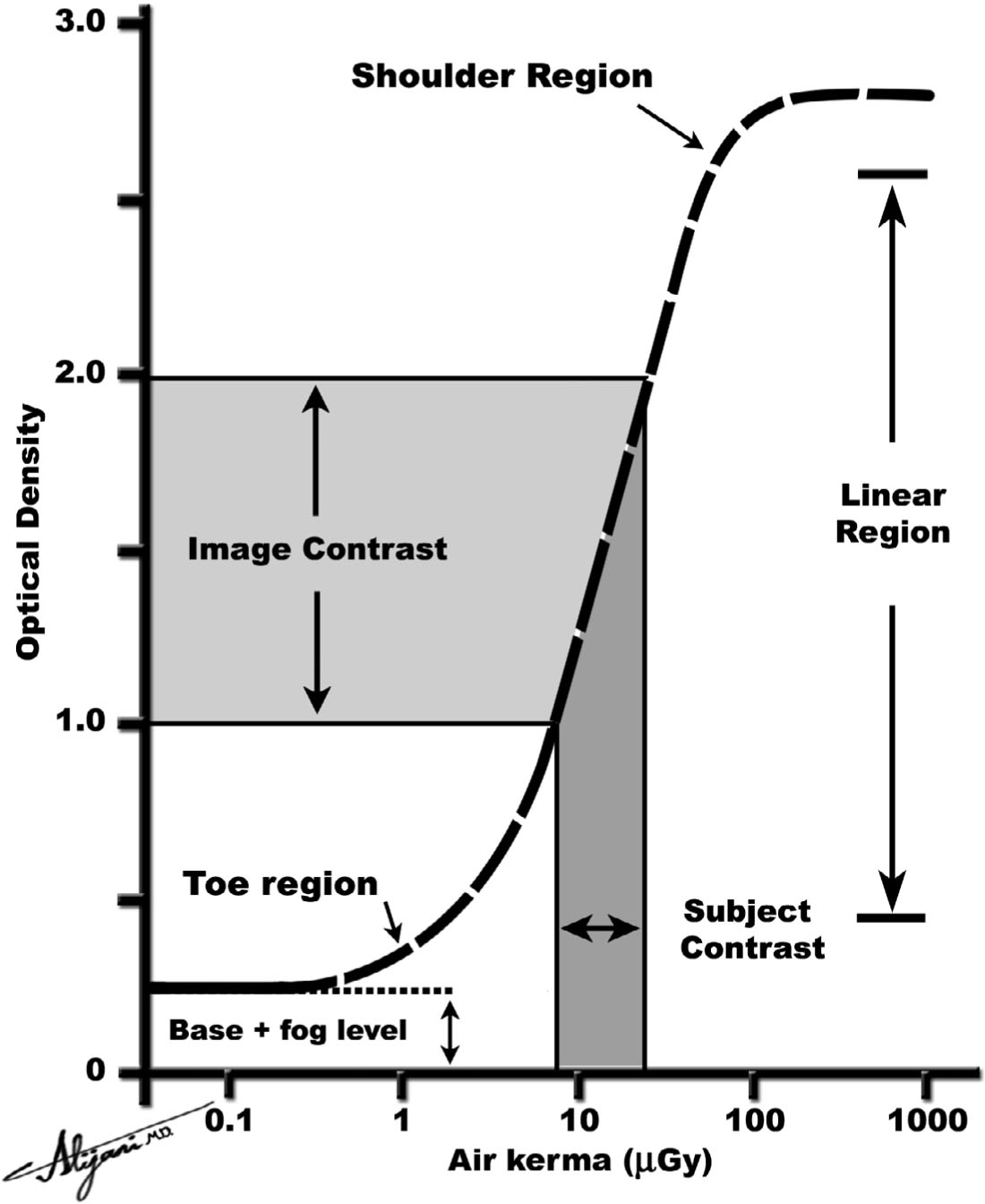
FIGURE 3.1 Characteristic curve showing relation between radiation intensity (air kerma) and optical density for a radiographic film.
–The maximum OD for exposed film is ~3.0 OD units.
–Fast films require less radiation to achieve a given film density.
–Slow films require more radiation.
A. Screen rationale
–A film alone (i.e., no screen) absorbs only ~1% of the incident x-rays, with the remaining 99% being wasted.
–Intensifying screens contain phosphor crystals that absorb about 50 times more of the incident x-rays than a radiographic film.
–For each x-ray absorbed in a screen, hundreds of visible light photons are produced that expose the film.
–The screen therefore converts the x-ray pattern to a light pattern, which is subsequently recorded on radiographic film.
–Intensifying screens improve the efficiency of radiographic imaging over film alone.
–The use of intensifying screens decreases the exposure time required for a given film density.
–Shorter exposures result in a lower patient dose.
–Shorter exposure times decrease x-ray tube loading.
–Shorter exposures also decrease blur caused by patient motion.
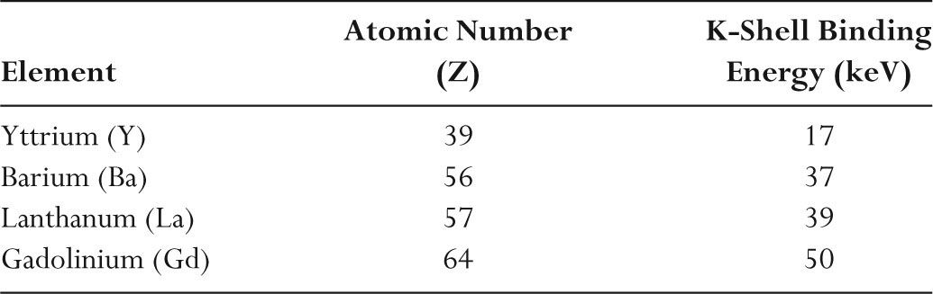
TABLE 3.2 Elements Used in Rare Earth Screens
B. Screen materials
–Screens contain high atomic number materials to maximize the absorption of x-rays.
–Calcium tungstate (CaWO4) was used in intensifying screens until about 1970.
–Tungsten has a high K-shell binding energy (70 keV), which is higher than the mean photon energy levels normally used in diagnostic radiology.
–The high K-edge energy of tungsten (W) means that x-ray absorption is less than optimal.
–Rare earth screens are ”faster” than calcium tungstate because they have a higher absorption efficiency at the x-ray energies normally used in radiology.
–Rare earth screens also have higher conversion efficiencies, producing more light for a given amount of deposited x-ray energy.
–The typical conversion efficiency of common screens is ~10%.
–A 10-keV x-ray photon absorbed in a screen thus produces a total of 1 keV of light energy (i.e., 10% of the 10 keV that is absorbed).
–1 keV of light energy corresponds to ~500 light photons given that one light photon has ~2 eV of energy.
–Table 3.2 lists common elements used in rare earth screens.
C. Screen characteristics
–A common screen thickness is ~200 μm.
–Lanthanum oxybromide (LaOBr) and calcium tungstate (CaWO4) emit mainly blue light.
–Gadolinium oxysulfide (Gd2O2S) emits mainly green light.
–The light color from a screen and the light sensitivity of the film must be matched.
–Matching the light emitted by the screen with film sensitivity is known as spectral matching.
–Conventional film is sensitive to ultraviolet and blue light.
–Orthochromatic film is also sensitive to green light.
–Screen absorption efficiency refers to the percentage of x-ray photons absorbed in the screen.
–A typical screen–film combination used to perform chest radiography absorbs ~50% of the incident x-ray photons (i.e., absorption efficiency is 50%).
–The intensification factor is the ratio of exposures, without and with intensifying screens, required to obtain a given film density.
–Intensification factor depends on the absorption and conversion efficiency of the screen.
–Typical intensification factors are 30 to 50.
D. Cassettes
–The film and screens are held in a light-tight cassette.
–Figure 3.2 shows a cassette with two screens and a double-emulsion film.
–Screens are usually permanently mounted inside the cassette.
–A thin layer of foam backing holds the screen tightly against the film when the cassette is closed.
–The front of the cassette is made of a minimally attenuating material such as aluminum or carbon fiber.
–Dual-screen, dual-emulsion systems are frequently used to improve x-ray absorption.
–Intensifying screens can be significant sources of image artifact.
–Scratches, stains, hair, dust, cigarette ash, and talcum powder are all potential sources of image artifacts.
–As part of a quality control (QC) program, all screens should be regularly cleaned.
–Cassettes should also be evaluated for good screen–film contact.
–Screen–film contact is evaluated by taking an image of a wire mesh and ensuring that the resultant image permits visualization of the mesh.
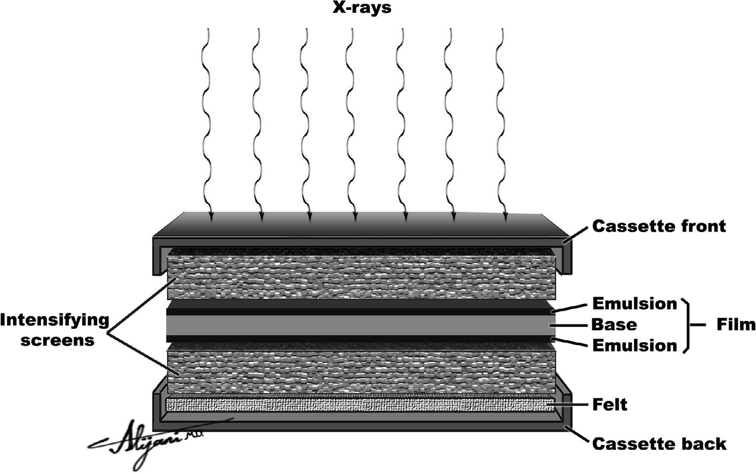
FIGURE 3.2 Cross section of a typical screen–film cassette containing double emulsion film and two screens.
–To ensure the correct film density, automatic exposure control (AEC) systems are generally used.
–AEC is also known as phototiming.
–An AEC measures the actual amount of radiation incident on the screen–film and terminates the exposure when the correct amount has been received.
E. Screen–film speed
–An air kerma of~ 10 μGy produces a satisfactory film density in a 100 speed screen–film combination.
–Both screen and film must be specified when assigning speed to any screen–film combination.
–The speed of a screen–film combination is inversely related to the air kerma required to produce a given density.
–As the speed increases, the air kerma required decreases.
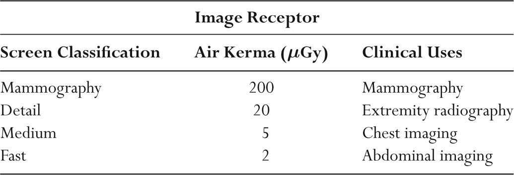
–A 200 speed screen–film combination requires an air kerma of 5 μGy, and a 50 speed screen–film combination requires an air kerma of 20 μGy.
–Speeds of screen–film combinations used in radiology range from 50 to 800.
–Screen speed increases with increasing screen thickness, absorption efficiency, as well as conversion efficiency.
–Fast screens are generally thicker.
–Whereas slow (detail) screens are thinner.
–Fast screen–films are used for abdominal studies whereas slow screen–films are used for extremity examinations.
–Single-emulsion, single-screen systems are used for bone detail and mammography.
–Table 3.3 lists a range of screen types used in radiology.
A. Computer basics
–Computers use the binary system (base two).
–A bit (binary digit) is the fundamental information element used by computers and can be assigned one of two discrete values.
TABLE 3.3 Screen Characteristics and Common Clinical Applications
–One bit can code for two values, or two shades of gray, which correspond to white and black.
–n bits can code for 2n values, or gray levels.
–The American Standard Code for Information Exchange (ASCII) uses 8-bit groups (designated a byte) to represent common letters and symbols.
–8 bits = 1 byte; 2 bytes = 1 word (16 bits).
–A total of 256 shades of gray (28) can be coded for by 1 byte (8 bits).
–4,096 shades of gray (212) can be coded for by 12 bits.
–Memory and file storage requirements for computers are normally specified using kilobyte (kB) (1,024 bytes) or megabyte (MB) (1,024 kB).
–One kilobyte is 1,000 bytes in the decimal system and 1,024 bytes in the binary system and which are taken to be equivalent for most practical purposes.
–Large storage requirements are specified using gigabyte (GB) (1,024 MB).
–Radiology departments have very large storage requirements, normally measured in terabyte (TB) (1,024 GB).
B. Computer hardware
–Computer hardware refers to the physical components of the system including the central processing unit (CPU), memory, and data entry and export devices.
–Computer memory stores the various bit sequences and is either random access memory (RAM)or read only memory (ROM).
–RAM is temporary (volatile) memory that stores information while the software is used.
–RAM is the primary memory component in most computers.
–ROM is for permanent storage and cannot be overwritten.
–Important CPU instructions for system operation are stored in ROM.
–Buffer memories are normally considered a part of RAM and are used for video displays.
–Cache memory provides transitional memory storage and is often built into CPU chips to provide a buffer between RAM and disc memory.
–Address refers to the location of bit sequences in memory.
–CPUs perform calculations and logic operations by manipulating bit sequences under the control of software instructions.
–Parallel processing occurs when several tasks are performed simultaneously, and requires multiple CPUs.
–Serial processing refers to performing tasks sequentially.
–Array processors are hard-wired devices dedicated to performing one type of rapid calculation.
–Array processors are used in CT and MR imaging where large numbers of calculations are needed to convert data into images.
–A bus is a local pathway linking components.
C. Computer software
–Computers use operating systems to perform internal system bookkeeping activities such as storing files.
–A file is a collection of data treated as a unit.
–Examples of operating systems are WINDOWS (IBM), MAC OS (Apple), UNIX and LINUX (SUN), and VMS (mainframe computers).
–Computer software instructs the computer where input data are stored, how these data are to be manipulated, and where the results are to be placed.
–Most computer programs are written using high-level languages such as C, Pascal, COBOL, dBase, FORTRAN, or Basic.
–Object code or machine language is the machine-specific binary code instructions used by the CPU.
TABLE 3.4 Typical Storage Capacities and Access Times for Computer Storage
Related posts:


Stay updated, free articles. Join our Telegram channel

Full access? Get Clinical Tree


