Figure 30.1 Novel variation of the “babygram” obtained with three separate radiographic exposures on a single 14 × 17-inch field. Each upper extremity, including a portion of the hemithorax, as well as the lower half of the body, were exposed separately.
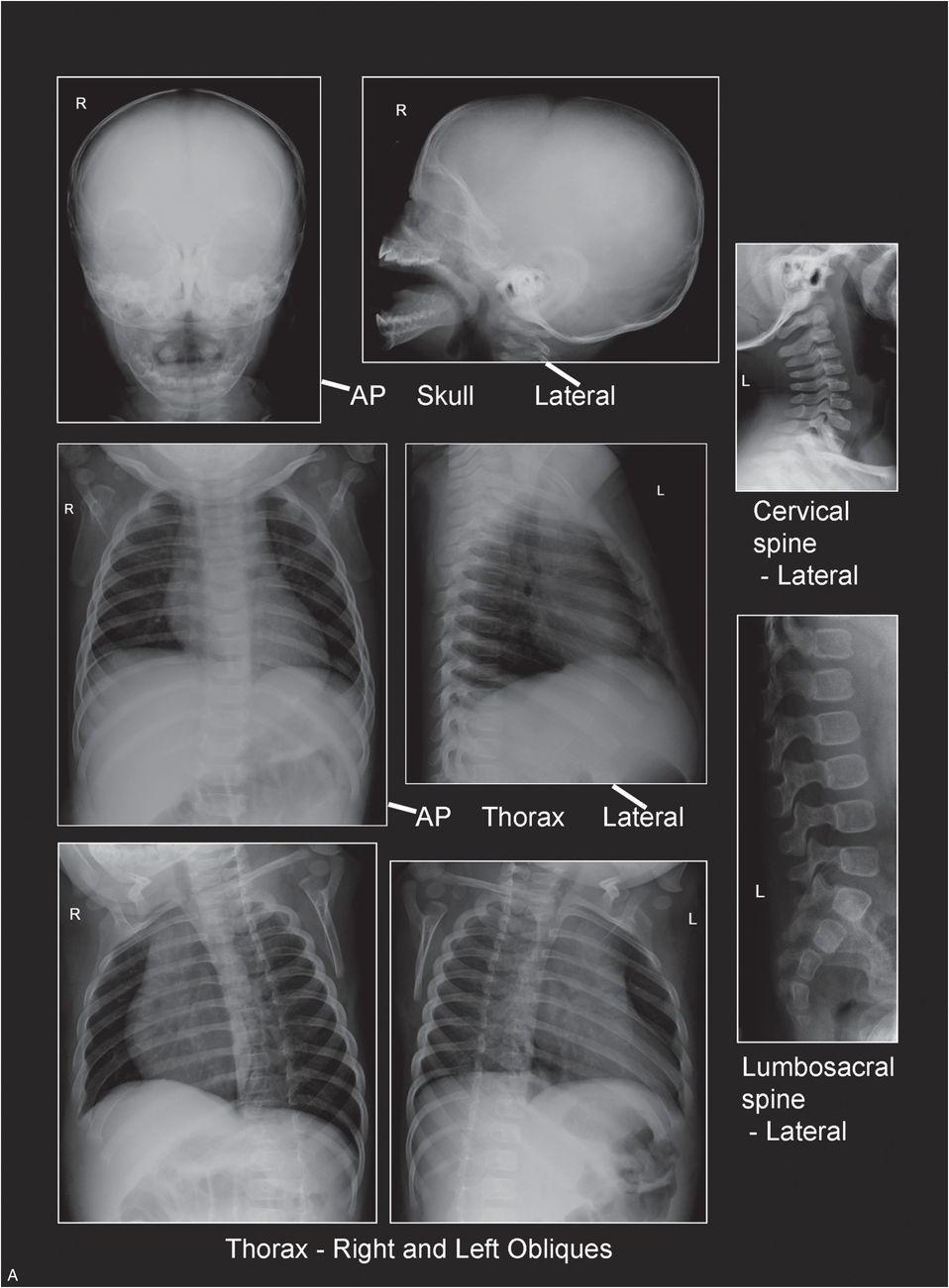
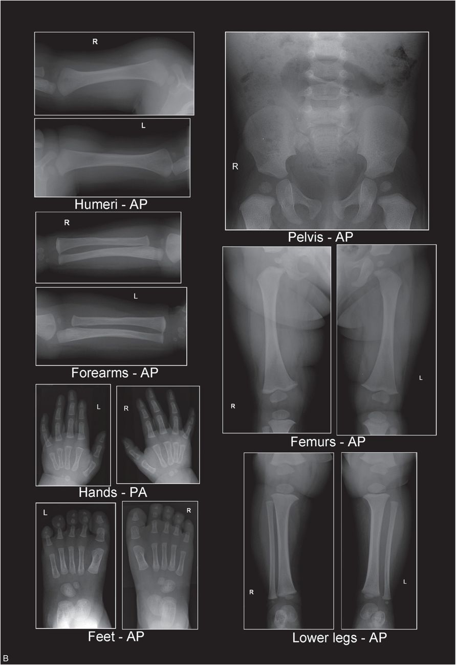
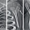
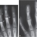
Figure 30.2 A, B, Recommended radiographic SS.
Radiology departments in large institutions as well as smaller facilities can perform high-quality pediatric SSs with modest, but rigorous adjustments to routine radiographic examinations. Radiographic equipment, imaging systems, and processing methods/parameters currently employed in most radiology departments can be adapted for use in pediatric SS imaging.
Digital radiographic imaging
Computed radiography (CR) and digital radiography (DR) have gradually replaced traditional film/screen imaging (see Chapter 28). Although digital radiographic images are lower in spatial resolution than high-detail film/screen images, the higher contrast and post-processing capabilities of CR/DR have the potential to provide comparable, and perhaps superior diagnostic performance for skeletal imaging (19, 20). Digital acquisition modes (when available) and exposure factors should be selected to optimize tissue contrast, spatial resolution, and signal/noise. Digital processing menus and image display parameters should be chosen to enhance bone detail.
Radiographic physics survey and calibration
Whether a department uses state-of-the-art radiographic equipment or older x-ray machines, most units can produce high-quality images when properly maintained. Acceptance testing of radiographic equipment immediately following installation and before clinical use should be implemented. Maintenance should include an annual physics survey along with an ongoing QA/QC program to monitor any variations in radiographic equipment performance. Regular performance testing and calibration of equipment should be done in accordance with equipment manufacturer specifications, industry standards, and applicable state and federal regulations (8).
The radiologic technologist can play a major role in maintaining the integrity of the radiographic equipment by informing responsible technical staff of fluctuations in equipment use between physics surveys, QC tests, and calibration checks. It is often the technologist who first encounters problems with radiographic equipment during its use. If issues are addressed promptly, minor adjustments can save hours of equipment down time and avoid additional patient radiation dose from repeat exposures. Radiographers should inspect digital systems daily for possible physical defects and perform phantom testing for image quality and artifacts. Daily secondary erasure of imaging plates should be performed at the start of each work shift to prevent exposure artifacts. Display and diagnostic monitors should be regularly inspected and tested by physicists using the Society for Motion Picture and Television Engineers (SMPTE) or American Association of Physicists in Medicine (AAPM) test patterns.
Radiographic equipment should be calibrated annually in conjunction with the physics survey. Any calibrations or service performed on the radiographic equipment should be documented for verification. Proper maintenance of radiographic equipment directly affects image quality and patient dosage. An annual physics survey is essential to keep radiographic equipment working properly and to produce consistently high-quality pediatric skeletal images. The physics survey should include radiographic unit assembly evaluation, focal spot evaluation, half-value layer measurement, peak kilovoltage (kVp) and timer accuracy, tube current (milliamps; mA) linearity, reproducibility, light to x-ray field alignment/central ray accuracy test, and image quality evaluation. Any equipment failures should be documented, corrected, and retested for compliance. Typical patient entrance exposures for various examinations can also be calculated (and adjusted when necessary) by the physicist during this survey and should be posted in the x-ray room. Regulatory agencies and accrediting organizations, such as the Joint Commission for the Accreditation of Hospital Organizations (JCAHO) and the ACR, frequently require this information (8).
The SS examination
Basic principles and imaging protocol
The fundamental principle underlying the SS protocol is tight collimation of the x-ray beam over each anatomic region of interest. Proper collimation reduces unwanted scatter radiation that causes image unsharpness and contributes no useful information to the final radiograph. Tight collimation over each anatomic region also contributes to uniform image density and prevents unnecessary exposure and scatter radiation to other body parts – thereby reducing the total patient dose (21, 22). Collimation is particularly critical in DR because image receptors are more sensitive to low levels of radiation, and the resulting digital image may demonstrate reduced image contrast because of excess scatter radiation striking the receptor (8). CR image receptors should be stored in a location shielded from radiation exposure until employed for imaging. After a CR image receptor has been exposed, it should be removed from the area and processed as soon as possible to avoid any additional exposure that may degrade image quality. In addition, tight collimation and centering over the anatomic region being examined are essential since the digital imaging detector may use the entire irradiated field in processing of the final displayed image.
Appropriate processing menus should be used to ensure image quality. While DR image processing can allow for multiple exposures on various locations on a single imaging plate, positioning of the anatomic region of interest on a CR plate may be more critical to the final processed image. Electronic masking to improve image viewing should be applied in a manner that demonstrates the actual exposure field edge to document appropriate collimation. Masking or cropping should not be used as replacements for beam restriction achieved through physical collimation of the x-ray field size (8, 23).
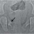
The central ray of the x-ray beam should enter each anatomic region at its midpoint. Geometric distortion increases when areas of interest are positioned farther away from the central ray (21, 22). With the “babygram,” the central ray is often placed over the trunk of the infant and the portion of the image encompassing the extremities is distorted, owing to the increased angulation of the x-ray beam at the periphery of the field.
The “babygram” is of historical interest only – it has no place in the modern approach to global skeletal assessment. The currently recommended initial SS imaging protocol consists of 21 separate images of each anatomic region, with frontal views of the appendicular skeleton, frontal and lateral views of the axial skeleton, and oblique views of the thorax (Table 30.1, Fig. 30.2) (6).
| Axial skeleton | Appendicular skeleton |
|---|---|
| Skull (AP and lateral) | Humeri (AP) |
| Cervical spine (lateral) | Forearms (AP) |
| *Thorax (AP, lateral, both obliques) | Hands (PA) |
| †Pelvis (AP) | Femurs (AP) |
| Lumbosacral spine (lateral) | Lower legs (AP) |
| Feet (AP) |
Related posts:

Stay updated, free articles. Join our Telegram channel

Full access? Get Clinical Tree


