Clinical Presentation
The patient is a 21-year-old man who has had intermittent severe low back pain for 2 years. Pain began immediately after lifting a heavy object. Patient has not been completely pain free for 2 years. Presented with low back pain; the reported visual analog scale (VAS) was 6/10 with pain medication (hydrocodone 4 times daily), and VAS was reported to be 9/10 with no pain medication. Physical therapy, vertebral axial decompression (VAX-D) therapy, and three epidural steroid injections did not relieve the pain. The patient had been told he had an incidental cyst in the L3 vertebral body that required no therapy.
Imaging Presentation
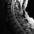
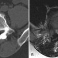
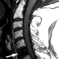
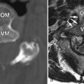
Computed tomography (CT) reveals a small Schmorl’s node at the superior endplate of L2 and a large cystlike Schmorl’s node in the superior portion of the L3 vertebral body ( Fig. 64-1 ) . A rim of sclerosis is seen adjacent to both Schmorl’s nodes. On T1-weighted images ( Fig. 64-2 ) , zones of variable signal intensity surround the nodes. T2-weighted magnetic resonance (MR) images ( Fig. 64-3 ) show a fluid-level within the large cystic Schmorl’s node, with surrounding marrow edema. A peripheral rim of contrast enhancement surrounds the larger Schmorl’s node, whereas the smaller Schmorl’s node enhances centrally ( Fig. 64-4 ) .


Clinical Course
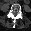
Both the small L2 and larger L3 Schmorl’s nodes were proved to be major low back pain generators by discography. During discographic injection, the patient reported intense back pain precisely when the intradiscal contrast agent entered the Schmorl’s node ( Fig. 64-5 ) . The cystic L3 Schmorl’s node was treated by a transpedicular injection of 2 mL of methylmethacrylate cement directly into and around the cystic cavity. The L2 Schmorl’s node was treated 3 months later using a transpedicular approach to inject cement into the marrow substance adjacent to the node. The patient’s pain level 3 weeks after treatment was VAS = 2/10 with no pain medication.

Discussion
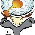
Schmorl’s nodes represent focal protrusions or herniations of the intervertebral disc through the vertebral endplate. This localized vertebral endplate deformity was first described by the German pathologist Christian G. Schmorl in 1927. Schmorl’s nodes may occur in either the inferior or superior endplate, although the inferior endplate is said to be a more common site. They reportedly occur more frequently in males and more commonly near the thoracolumbar junction. The “classic” Schmorl’s occurs in the middle one third of the vertebral endplate and is most commonly located slightly posterior to the central axis of the vertebral endplate ( Fig. 64-6 ) . The typical Schmorl’s node occurs near the midline, but paramidline locations are also common. Over time, the usage of the term Schmorl’s node has expanded in scope and now is used to describe nearly any endplate depression, focal or diffuse, regardless of location.

The pathogenesis of the Schmorl’s node remains controversial. Schmorl’s nodes may be idiopathic, developmental, or acquired. The etiology of so-called idiopathic and developmental Schmorl’s nodes are likely the same, probably arising from some preexisting endplate deformity, anomaly, or subchondral osteonecrosis (ischemic necrosis) that weakens the endplate, predisposing it to herniation of the nucleus pulposus through the endplate. These endplate anomalies can be small ossifications, pits, or defects that arise where endplate vascular or nutrient channels exist or once existed. The nucleus pulposus is a remnant of the notochord.
Incomplete notochordal regression may also leave behind endplate defects, which are typically midline and slightly posterior to the central axis of the vertebral body. Such congenital Schmorl’s nodes can be seen on images early in life as isolated or multiple vertebral endplate defects adjacent to the nucleus and may be associated with abnormally shaped vertebral bodies ( Fig. 64-7 ) . Scheuermann-type vertebrae (juvenile kyphosis) may have Schmorl’s nodes along their vertebral endplates, usually located anteriorly. The limbus vertebra, rarely seen in children but not uncommonly seen in adults, is thought to result from herniation of the nucleus pulposus through the ring apophysis prior to fusion, resulting in an isolated anterior ring apophyseal fragment.