Introduction
Fractures and other abnormalities involving the skull and face were covered in Chapter 2 . Initial imaging studies for a number of clinical problems are presented in Table 8.1 . A few general comments should be made about the structure of bone. Most bones consist of a densely calcified cortex, or shell, that surrounds the medullary space. The medullary space contains either active (red) marrow or fatty replaced (yellow) marrow. In the adult, red marrow is found in the skull, ribs, spine, pelvis, and proximal portions of the femurs and humeri. Because this red marrow acts as a filter, most bone metastases begin in these locations and chew outward until they involve the cortex.
| Clinical Problem | Imaging Study |
|---|---|
| Fracture (acute or follow-up) | Plain x-ray |
| Cervical spine trauma | Low risk by NEXUS or CCR criteria [see text] imaging usually not appropriate) High-risk imaging with plain x-ray and possibly CT or MRI |
| Thoracic, lumbar spine trauma | Plain x-ray or CT (spinal fracture at one level indicates risk for spinal fractures elsewhere) |
| Stress fracture | Plain x-ray (if negative, do MRI) |
| Metastasis | Nuclear medicine bone scan, plain x-ray in area of pain |
| Osteomyelitis | Plain x-ray; if negative, then MRI or nuclear medicine, three-phase bone scan |
| Neck pain (chronic) | Plain x-ray (if negative and neurologic signs and symptoms, then MRI or CT) |
| Low back pain | |
|
|
| Persistent or progressive symptoms during or after 6 weeks of conservative therapy | MRI without contrast |
|
|
|
|
|
|
|
|
|
|
| Osteopenia or steroid use | X-ray |
| Cauda equina syndrome | MRI |
| Arthritis (nonseptic) | Plain x-ray |
| Suspected septic arthritis | Joint aspiration, plain x-ray |
| Monoarticular joint pain | Plain x-ray; if conservative therapy fails, then MRI |
| Shoulder acute pain | Plain x-ray (if negative, then MRI without contrast) |
| Shoulder acute pain (postsurgical repair) | MRI |
| Shoulder persistent pain (negative x-ray) | MRI |
| Elbow chronic pain | Plain x-ray (if negative, then MRI without contrast) |
| Wrist or hand trauma | Plain x-rays with at least three projections (and CT if intraarticular fracture) |
| Hip trauma | Plain x-rays of hip and pelvis (if negative and suspicion remains, then MRI) |
| Hip (suspected avascular necrosis) | Plain x-ray (if negative or equivocal, then MRI) |
| Knee pain (nontraumatic) | Plain x-ray (if negative or effusion, then MRI) |
| Knee, ankle, or foot acute trauma | See text for Ottawa Rules on appropriateness of x-rays |
| Knee replacement (routine follow-up) | Plain x-ray |
| Pain after knee replacement | Plain x-ray and aspiration (if negative, then nuclear medicine infection scan) |
| Knee replacement (suspected loosening) | Plain x-ray (if negative for infection, then CT) |
| Chronic ankle pain | Plain x-ray (if negative and suspected tendon or osteochondral injury, then MRI) |
| Chronic foot pain | Plain x-ray (if suspected ligamentous or tendon issues or neuroma, then MRI) |
| Reflex sympathetic dystrophy | Plain x-ray; if negative, then three-phase nuclear medicine bone scan |
| Soft tissue mass | Plain x-ray; if negative, then MRI with and without contrast |
The midportion of the long bones is referred to as the diaphysis. Toward the ends of long bones is the metaphysis, which extends up to the epiphyseal plate. Beyond the epiphyseal plate is the epiphysis. An epiphysis, by definition, involves a joint space. Occasionally, growth centers are found on portions of long bones where the joint space is not involved (e.g., along the greater trochanter of the femur). These centers are referred to as apophyses .
Growth of long bones occurs primarily at the epiphyseal plate, when new bone is added to the lengthening metaphysis and the epiphyseal plate moves farther along. Some growth occurs along the lateral periosteum as well to allow the bones to become thicker with age. Some epiphyses are present at birth, and most are closed by the age of 20 years. The different parts of long bones are important because some lesions will preferentially affect only certain parts of the bone. For example, it is common for a Ewing sarcoma to affect the diaphysis of a long bone, but it will rarely, if ever, affect the epiphysis.
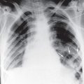
The cortex of bone has fine white lines, which are referred to as trabeculae. These are located predominantly along the lines of stress in the bone, and they provide little pillars of support. Occasional cross-linking trabeculae occur. With disuse, old age, or states of increased blood flow, calcium is carried away from bone. This does not occur in a random fashion but preferentially removes the cross-linking trabeculae first. As the process becomes more advanced, the trabeculae along the lines of stress are removed, and the bone becomes weakened and may be subject to compression fractures. This process is seen in older women. Often, in a woman with osteoporosis, you will see only the outline of the thoracic vertebral bodies on the lateral chest x-ray because the trabeculae have been resorbed, and many midthoracic and upper thoracic wedge compression fractures are found. As is shown later, with disuse of an extremity or in a hyperemic state, initial resorption of calcium occurs in a periarticular distribution because more blood flow is found here than along the shafts of bones.
A few final words of caution before we begin. Most bone lesions will be relatively obvious to you as a result of the clinical history. More than 95% of bone radiographs are obtained for the evaluation of trauma, arthritis, degenerative conditions, or metastasis. A number of classic fractures must be recognized; a few, if missed, can have dire consequences (especially cervical spine fractures). It is crucial that you spend time on these. Although some details of the various arthritic conditions are presented, these are relatively nonspecific and are certainly not emergencies or life threatening. Primary bone tumors are very rare, and you should not expect to develop competence regarding these. In clinical practice, other than orthopedics or oncology, you probably will see a primary bone tumor once every 5 or 10 years. Most radiologists see fewer than three or four bone tumors per year. The main point is to be able to discern the lesions and refer them to a radiologist for a reasonable differential diagnosis. Bone metastases for most tumors are best imaged with a plain x-ray of the suspicious site and a nuclear medicine bone scan. Soft tissue masses are best imaged with an x-ray of the site and, if needed, magnetic resonance imaging (MRI).
Cervical Spine
Normal Anatomy
The lateral view of the cervical spine is the initial view obtained, particularly in trauma cases. Box 8.1 provides a summary of how to evaluate a cervical spine examination done for trauma. Initial inspection should be directed toward the various contour lines of the cervical spine, shown in Fig. 8.1 . These include the anterior soft tissues, the anterior and posterior spinal line, the spinal laminal line, and the posterior spinous process line. On the lateral view, the cervical spine should be bowed forward and have a relatively smooth curve. No sharp angulation should be found at any level. If the patient was lying on a stretcher when the lateral view was taken, the neck is often somewhat flexed and the cervical spine is straight rather than curved. When you see this, you cannot be sure whether the straightening is due simply to the supine positioning of the patient or to muscular spasm. If the trauma was relatively minor, an upright lateral x-ray of the cervical spine usually will solve the problem. If major trauma is suspected, a computed tomography (CT) or MRI scan may be needed.
Lateral View
Count vertebral bodies to ensure that all seven are seen (if not, consider swimmer’s view or shallow oblique view)
Alignment
Anterior vertebral body margins
Posterior vertebral body margins
Posterior spinal canal
Cervical curvature, straightening, or sudden angulation
Prevertebral soft tissue thickness (see text)
Widening of vertical distance between posterior processes
Common fractures
C1 arch
C2 odontoid
Arch (hangman’s)
Widening between anterior arch of C1 and odontoid
C3-C7 anterior avulsion
Wedge compression
C6-C7 posterior process (clay shoveler’s)
Facets (to exclude unilateral locked facet)
Anterior View
Odontoid view
Widening of the lateral portion of C1 relative to C2 (Jefferson fracture)
General alignment of lateral margins and spinous processes
Lucent fracture lines
Oblique View (if No Major Trauma Suspected)
Neural foraminal narrowing
Alignment of facet joints


Examination of the anterior soft tissues and spaces should be done at several vertebral levels. Evaluation of soft tissue width is typically not a problem unless the patient has an endotracheal tube in place, in which case the normal air and soft tissue interface is obscured and you will have to rely on other findings. The actual width of the prevertebral soft tissues as measured on an image is of course dependent on the level of magnification when the x-ray was taken. On a portable trauma series with the patient supine, the x-ray tube is often only 40 inches from the detector. As a result, significant magnification is seen, and a measurement of up to 7 mm may be normal in the prevertebral soft tissues at the C3 level. However, if the examination was done with the tube 72 inches, or 6 feet, from the detector, the soft tissue normally should not exceed 4 to 5 mm.
Below the level of C4, the air column moves anteriorly in the region of the larynx; thickened soft tissue between the larynx and the vertebral bodies is due to the esophagus. Soft tissue anterior to the lower cervical bodies averages about 15 mm, with a range of 10 to 20 mm. If the soft tissue in this region equals or exceeds the width of the vertebra at or below the level of C4, pathology should be suspected.
Another measurement to note on the lateral view is the distance from the posterior aspect of the anterior arch of C1 to the most anterior portion of the odontoid. In an adult, this should not exceed 3 mm; in a child, it should not exceed 5 mm.
Examination of the bony contour lines is done to exclude subluxations. Remember that on the lateral view, you should be able to see down to at least the bottom of the C7 or the top of the T1 vertebral body. If it is difficult to see this far down because the patient’s shoulders are in the way, a swimmer’s view can be ordered. For this view, one of the patient’s arms is raised next to the head and the other arm placed down alongside the waist. This essentially raises one shoulder and lowers the other, allowing the x-ray beam to penetrate the area of the cervicothoracic junction more easily ( Fig. 8.2 ).

Typically, two anterior views are done after the lateral cervical spine view has been examined by a physician and found to be free of fracture or subluxation. First is the anterior view of the lower cervical spine with the mouth closed; this view is used to examine alignment and to exclude oblique fractures. In addition, an open mouth view of the odontoid is obtained ( Fig. 8.3 ). This view shows the relation of the inferior aspect and lateral margins of C1 to the superior aspect and lateral margins of C2, and it also shows the odontoid very well. It is important to have the mouth open wide enough that the front teeth do not overlie the odontoid. If this happens, you can see the air gap between the two front teeth and mistakenly call this a fracture ( Fig. 8.4 ).


Two relatively common normal variants appear on the lateral view. The first of these looks like a calcified spike or nail and represents calcification of the stylohyoid ligament. It is actually quite lateral, but on the lateral cervical spine view it projects posterior to the mandible and anterior to C1 and C2 ( Fig. 8.5A ). Another common variant is embryologic fusion of two or more vertebral bodies to create a block vertebra; this may be a complete or incomplete fusion ( Fig. 8.5B ). Often, a block vertebral body will cause abnormal motion, with associated early degenerative changes.

Oblique views of the cervical spine are obtained only when you are quite sure that no major trauma, fracture, or dislocation is present. The value of oblique views is mostly to see whether impingement and narrowing of the neural foramina by bony degenerative spurs are present. On a good oblique view, you should be able to see the neural foramina very well from C2 down through T1 ( Fig. 8.6 ). In addition, look to see that the articular facets are lined up like shingles on a roof. This view may be helpful to see a unilateral perched, subluxed, or locked facet if CT is not available. Both CT and MRI are useful for imaging the cervical spine. CT is best suited for detecting subtle bony fractures, whereas MRI provides exquisite detail of soft tissues, such as the spinal cord, and cerebrospinal fluid (CSF; Fig. 8.7 ).


Trauma
Of acute traumatic spinal fractures, 50% are due to motor vehicle accidents, about 25% to falls, and about 10% to sports injuries. The most common sites are the upper (C1 to C2) and lower (C5 to C7) cervical spine and the thoracolumbar junction (T9 to L2). Twenty percent of spinal fractures are multiple, and about 5% occur at discontinuous levels.
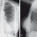
Dislocation of the skull from the cervical spine (atlantooccipital dislocation) is rare and usually fatal. Approximately 5% of cervical spine fractures involve C1. Fractures of the atlas can involve any portion of the bony ring. Combination fractures, or burst fractures, of the ring of C1 are called Jefferson fractures . This bursting is usually secondary to axial loading as a result of the skull being smashed down onto the cervical spine (as in diving into a shallow pool; Fig. 8.8A ).

Approximately 10% of all cervical spine fractures involve the odontoid process of C2. The most common type of odontoid fracture occurs at the base of the odontoid process. You can identify the fracture on the lateral view by being careful to trace the anterior and posterior cortex of the odontoid process. Often, associated soft tissue swelling is found (see Fig. 8.8B ). Note that in young children the odontoid may not be completely fused to the body of C2, and this should not be mistaken for a fracture (see below, Fig. 8.170A ).
Occasionally, C1 to C2 injury of the transverse ligament may occur, causing traumatic atlantoaxial subluxation. Although this may occur with an associated odontoid fracture, it can also occur without it. If no fracture is present, the subluxation is often fatal, because the odontoid process pushes posteriorly into the spinal cord contained within the arch of C1. On the lateral view, the only sign of ligament injury may be some soft tissue swelling anterior to the vertebral bodies. Flexion views will sometimes demonstrate increased widening not only of the atlantoaxial space but also of the space between the posterior spinous processes. This type of subluxation also occurs as a complication of rheumatoid arthritis (RA) ( Fig. 8.9 ).

A relatively classic fracture of C2 is what is referred to as the hangman’s fracture. This involves fracture of the posterior elements of C2, often with associated spinal cord compromise. This fracture typically occurs secondary to hyperextension and compression of the upper cervical spine, and usually anterior subluxation of the body of C2 relative to C3 is found ( Fig. 8.10 ). In spite of the name, this is not the usual fracture that occurs as a result of judicial hangings.

Two rather characteristic fractures of the midcervical spine’s vertebral bodies can occur. The first of these is caused by hyperextension, which typically tears off either a superior or inferior anterior portion of the cortex from a vertebral body ( Fig. 8.11 ). A second type of fracture that commonly occurs in the middle cervical spine is a hyperflexion injury. In this fracture, compression of the vertebral body is found, usually with anterior wedging and sometimes with a posteriorly displaced disk fragment and with associated soft tissue swelling due to the hemorrhage. Evaluation with MRI may show compromise of the neural canal at the level of the fracture ( Fig. 8.12 ).


In addition to fractures associated with subluxation, a ligamentous injury may allow the facets of one vertebral body to become slightly subluxated, perched, or locked. These represent a more anterior subluxation of a superior vertebral body on a lower one. Generally these injuries occur in the lower half of the cervical spine and are caused by extreme flexion of the head and neck, without axial compression. Occasionally, a fracture or ligamentous injury cannot be identified with plain x-rays. If a high suspicion of clinical injury exists in spite of negative plain x-rays, CT scanning ( Fig. 8.13 ) or MRI may be useful. CT scanning is able to identify small cortical breaks, whereas the MRI scan can show areas of increased signal with hematoma or edema, suggesting at least a ligamentous injury.

Three fractures of the lower portion of the cervical spine are easily missed. Occasionally, oblique fractures of the lower cervical spine are seen only on the anteroposterior (AP) view ( Fig. 8.14 ). The second fracture involves the posterior spinous process at the C6, C7, T1, or T2 level. This is called the clay-shoveler’s fracture , and it is due predominantly to hyperflexion injury ( Fig. 8.15 ). A third and most significant problem relative to the lower cervical spine is accepting a trauma lateral cervical spine image that does not include adequate evaluation of C6 and C7. Failure to visualize this region can result in missing significant subluxations and fractures and, for purposes of complete evaluation, either a swimmer’s view or shallow oblique views through the cervicothoracic junction are necessary ( Fig. 8.16 ).


Plain AP and lateral x-rays historically were the primary screening tools for spinal trauma. Two sets of decision rules have been developed to determine which patients are at low risk and which patients benefit from plain x-ray studies. These are the National Emergency X-Radiography Utilization Study (NEXUS) and the Canadian C-Spine Rule (CCR). CCR applies only to stable patients (Glascow coma score 15) with blunt cervical trauma and not to patients who are younger than 16 years of age and have paralysis or a history of cervical disease or surgery. With NEXUS, a patient is considered at low risk and not in need of an x-ray if he or she meets all of the following criteria:
- •
No posterior midline cervical spine tenderness
- •
No evidence of intoxication
- •
Normal level of alertness
- •
No focal neurologic deficit
- •
No painful distracting injuries
With the CCR, a patient is referred for an x-ray if she or he is at high risk and meets any of the following criteria:
- •
Older than 65 years
- •
Dangerous mechanism of injury, such as the following: (1) a fall from 3 feet or higher, (2) a fall down five stairs, (3) axial load to the head, (4) motor vehicle accident at greater than 60 mph, (5) motor vehicle accident rollover or ejection, or (6) collision involving a motorized recreational vehicle or bicycle
- •
Has paresthesias in extremities
If the patient has no high risk factors and has any low risk factors (e.g., sitting position in ER, ambulatory at any time, absence of midline tenderness, delayed onset of neck pain, or slow speed rear end motor vehicle accident), the patient may be assessed for 45-degree left and right active range of motion. If the patient can perform this without difficulty, imaging is not recommended.
The CCR criteria are more sensitive and specific than the NEXUS criteria. At the present time, if a patient needs posttraumatic cervical spine imaging, a CT scan is usually done rather than simple radiographs. About 5% of the time, fractures are found that cannot be seen on plain x-rays. In addition, about 50% of the time, plain x-rays are unable to distinguish a vertebral body compression fracture from the more serious burst fracture. If a patient has severe head trauma requiring CT evaluation, most physicians simply continue the head scan down into the cervical spine to exclude occult fractures. MRI is better than CT for the detection of the soft tissue and spinal cord components of the injury. If a patient has had a normal CT scan but there is still suspicion of ligamentous damage, MRI is indicated. Box 8.2 shows the indications for MRI of the spine. If arterial injury is suspected, either computed tomography angiogram (CTA) or magnetic resonance angiogram (MRA) is indicated.
a A computed tomography scan also can be used if a magnetic resonance imaging scan is not available.
of the Spine
Radiculopathy: unchanged after 4 to 6 weeks of limited activity and medications; worsening or extension after 2 weeks of limited activity and medications
High-impact trauma
New or progressive neurologic deficit
Neurologic deficit inconsistent with radiographic findings
Suspected spinal tumor
Suspected spinal infection
Acute myelopathy (hyperreflexia, gait disturbance, clonus, numbness or paresthesia in legs)
Acute urinary retention or stool incontinence
Neurogenic claudication (differentiated from vascular claudication by partial relief with back flexion, onset with prolonged standing)
Cancer elsewhere with new spine pain, new spinal bone lesion on radiographic examination, new neurologic findings
Low back pain (with any of the following red flags):
- •
History of cancer, unexplained weight loss, immunosuppression, urinary infection, intravenous drug use, prolonged use of corticosteroids, no improvement or progressive symptoms during or after physical therapy and medical management
- •
History of significant trauma, minor fall or heavy lifting in older or osteoporotic patient, prolonged use of steroids
- •
History of acute onset of urinary retention or overflow incontinence, loss of anal sphincter tone or fecal incontinence, saddle anesthesia, global or progressive motor weakness in lower limbs
- •
Degenerative Changes
In terms of anatomic and mechanical design, the lower aspect of the cervical spine is less than optimal and, by the third or fourth decade of life, degenerative changes involving C4 through C7 are almost always found. Degenerative changes are visualized as decreased disk spaces, sclerosis (increased density) of the vertebral body end plates, and beaking or spurring of the anterior, lateral, and posterior margins of the vertebral bodies. Often, patients are initially seen with arm pain, and an oblique cervical spine view can easily visualize hypertrophic osteophytes or spurs projecting into the neural foramen ( Fig. 8.17 ). If a herniated cervical disk is suspected, the procedure of choice is an MRI scan. Metastatic disease also can involve the cervical spine, with posterior or lateral extension and impingement on the spinal cord or nerve roots ( Fig. 8.18 ).


Chronic Neck Pain
Chronic neck pain is very common and may be due to prior trauma (whiplash injury) or mechanical and degenerative abnormalities. X-rays are the mainstay of initial imaging. A subset of patients may benefit from MRI, including those with old trauma, neurologic findings, disk margin bone erosion, or suspicion of cancer. CT may be better for those who have had ossification of the posterior longitudinal ligament or prior anterior cervical discectomy and fusion.
Thoracic Spine
Anatomy
Plain x-rays of the thoracic spine are taken in AP and lateral projections. The AP projection is useful for examining spinal alignment, the paraspinous soft tissues (to exclude hematomas or other masses), and the pedicles ( Fig. 8.19 ). The lateral thoracic spine is usually a difficult image to assess. In the upper portion, the vertebral bodies are obscured by the shoulders; as mentioned in the discussion of the cervical spine, if you suspect pathology in the T1 to T5 region, a swimmer’s view or shallow oblique view is often necessary. The midthoracic and lower thoracic spine is usually well seen on the lateral view. When pathology is identified on the lateral view, it is often not easy to tell exactly the level of the vertebral body involved. Once you have identified pathology on the lateral view, you can usually go back to the AP view, look at the ribs, and then count up from T12. A common normal variant is seen on the lateral thoracic spine view in children. This apophysis, which occurs along the superior and inferior anterior margins of the vertebral bodies, should not be mistaken for a fracture ( Fig. 8.20 ).


Trauma
Fractures of the thoracic spine are typically the result of motor vehicle accidents or the normal aging process, with osteoporosis and resultant anterior wedging of vertebral bodies. Fractures due to significant acute trauma are sometimes seen well only on the AP or lateral view. On the AP view, you should examine the spine for malalignment of the posterior spinous processes ( Fig. 8.21 ) and paraspinous soft tissue swelling. These are both signs that a fracture may be present. If you suspect a spinal fracture, both AP and lateral views should be examined. Sometimes, significant subluxation of one vertebral body forward on another will be difficult to see on the AP view ( Fig. 8.22 ). This usually occurs when a hyperflexion injury results in a compression burst fracture. Often, retropulsed fragments of both disk and bony material project into the spinal canal and can cause significant compromise of the spinal cord. After significant blunt trauma, imaging with CT is indicated if there is back pain, midline tenderness, abnormal neurologic signs, C-spine fracture, Glasgow Coma Scale (GCS) less than 16, a major distracting injury, alcohol or drug intoxication, or local signs of thoracolumbar injury.


In older persons, compression fractures of the midthoracic and lower thoracic spine are common ( Fig. 8.23A ). These are noted as loss of height of the anterior portion of the vertebral bodies. It is almost impossible to tell whether any one of these fractures is new or old, but it usually does not make any difference clinically. In contrast to cervical injury, after trauma to the thoracolumbar spine, isolated unstable ligamentous injuries are rare in the absence of fractures, and MRI is not indicated unless myelopathy is present. If you suspect metastatic disease as a cause of back pain in an older patient, a plain x-ray and a nuclear medicine bone scan are usually satisfactory.

Degenerative Changes
Three relatively common degenerative findings are seen in the thoracic spine. The first are spurs or hypertrophic osteophytes, similar to those seen in the lower cervical spine. These are almost never a clinical issue and are not an interpretative problem unless they are very large, at which point they can cause confusing shadows on the AP or posteroanterior (PA) chest radiograph. These are pointed areas that project out to the side of the spine and are usually seen right over the proximal end of a rib. On the lateral view, these can look like lung nodules, but they always are seen to be projecting over the disk spaces (see Fig. 3.17 ).
A second relatively common degenerative change is calcification along the anterior ligament. This can cross over the length of several vertebral bodies (see Fig. 8.23B ) and is sometimes referred to by radiologists as DISH ( d iffuse i diopathic s keletal h yperostosis). It is of no clinical significance to the patient. The third relatively common degenerative change is calcification of an intervertebral disk ( Fig. 8.24 ). This can occur at almost any level in the spine but is seen most frequently in the midthoracic region. A single calcified disk is usually the result of degenerative change or trauma. If calcification is seen at multiple disk levels, consider diseases that cause hypercalcemia or rare entities such as ochronosis.

Lumbar Spine
Normal Anatomy and Imaging Techniques
The standard views obtained of the lumbar spine are AP and lateral views and a lateral spot view of the L5 to S1 area ( Fig. 8.25 ). The spot view is necessary because on the lateral view, both iliac wings and a significant amount of additional soft tissue mean that more radiation exposure is necessary to penetrate and visualize the L5 to S1 area adequately.
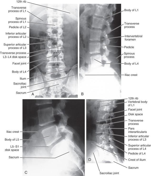
On the AP view, examine the alignment of the spine and the visibility of the psoas margins bilaterally. It is often useful to count the number of vertebral bodies because six, rather than five, non–rib-bearing vertebrae may be found. The transverse processes should be examined to exclude fracture, and the pedicles at each level should be examined to make sure that they have not been eroded by a pathologic process. In addition, the sacrum and sacroiliac (SI) joints should be examined. The SI joints can become fused in various arthritic processes (such as ankylosing spondylitis) or can be widened by a pelvic fracture.
On the lateral view of the lumbar spine, search for subluxation of the vertebral bodies; this is done by looking down the contour lines formed by the anterior and posterior margins of the vertebral bodies. The height and shape of vertebral bodies and the disk spaces should be uniform. The posterior spinous processes also can be visualized.
Oblique views of the lumbar spine are useful for examining the facet joints. The typical anatomy on the oblique view is seen as the outline of a Scottie dog (see Figs. 8.25D and 8.30B ). In this oblique projection, the pedicle is the eye of the Scottie dog and the transverse process represents the nose. The superior articular process forms the ears and the inferior articular process forms the front legs.
A common normal variant of the lumbar spine is incomplete fusion of the posterior aspect of L5 or S1 (spina bifida occulta), which is seen on the AP view ( Fig. 8.26A ). It is of no clinical significance and should be disregarded. A second common anomaly is sacralization, or partial fusion, of L5 with the sacrum (see Fig. 8.26B ). This can occur just on one side, or it can be bilateral.

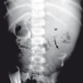
On any given view of the lumbar spine or pelvis, you can see normal bowel gas projecting over bone. This looks dark and can easily mimic a destructive bone lesion. I have seen several instances in which physicians told patients that they had “cancer of the spine,” which in reality was overlying bowel gas. Make sure that any bone lesion that you suspect is confined to the bone and stays within that bone on AP, lateral, and oblique views.
Postsurgical Changes
The most common postsurgical change involves lower lumbar fusion or laminectomy. It is often not easy to appreciate laminectomy on the lateral image; however, on the frontal views, it is much easier to see that one or more posterior spinous processes are gone ( Fig. 8.27 ). Noticing things that are missing is always harder than seeing abnormal objects that are present.

Fractures
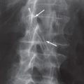
The most common fractures of the lumbar spine are wedge compression fractures and compression burst fractures. These are similar to those already described in the thoracic spine. Progression of compression fractions can be arrested, and pain sometimes can be relieved, by a procedure known as vertebroplasty . In this procedure, cement or glue is injected into the vertebral body ( Fig. 8.28 ). Again, it should be noted that compression burst fractures frequently have fragments that are retropulsed, and CT or MRI is often necessary to evaluate compromise of the spinal canal.

A somewhat unusual fracture occurs in the lumbar spine, typically at L1, L2, or L3, called a Chance fracture . In the past, this most commonly was the result of a motor vehicle accident when a lap seat belt was worn without the shoulder harness. Under these circumstances, rotation of the trunk of the body occurs about the horizontal axis of the seat belt, resulting in a vertical distraction force along the lumbar spine. This essentially tears a vertebral body (horizontally) in half. On the AP view, this fracture is recognized by discontinuity of the outline of the pedicles and, on the lateral view by a lucency extending through the posterior spinous process and lamina ( Fig. 8.29 ).

The pars interarticularis of the vertebral body can also be fractured. This injury typically occurs at the L4 or L5 level. It can sometimes be seen on the lateral view as a lucency but usually is clearly identified as a break in the neck of the Scottie dog on the oblique view ( Fig. 8.30 ). This finding was originally thought to be congenital, but most of the time it probably is the result of trauma in the early years of life. The term applied to a break in the pars interarticularis is spondylolysis. If bilateral spondylolysis is present, the vertebral body can slip forward on the vertebral body immediately below. When this happens, it is termed spondylolisthesis. The amount of offset caused by the slippage is used to grade the spondylolisthesis. If up to 25% of the vertebral body is offset, this is grade 1, between 25% and 50% is grade 2, and so on ( Fig. 8.31 ). In a young patient or athlete with low back pain and normal plain x-rays, a nuclear medicine bone scan with slices or single-photon emission CT (SPECT) scan may identify otherwise occult lesions ( Fig. 8.32 ).


Degenerative Changes
As mentioned earlier, degenerative changes can result in disk space narrowing, hypertrophic spurs (osteophytes; Fig. 8.33 ), or calcification of a disk. In the lumbar spine, loss of the disk space is quite common, as is hypertrophic spurring. Occasionally, you can see a thin dark line in a narrowed disk space ( Fig. 8.34 ), referred to as a vacuum disk phenomenon. Actually, it is not a vacuum; nitrogen is in the joint space. This can appear or be accentuated as a result of hyperextension of the spine, but it is a finding of no special clinical significance.


A common degenerative change that occurs in the lower lumbar spine is a herniated disk or protruded disk. A herniated disk often has a fragment that is asymmetric or loose in the neural canal, whereas a disk protrusion is a posterior central bulge of the disk. Both can be imaged with CT or MRI ( Fig. 8.35 ). Currently, MRI is commonly used to make this diagnosis.

Management of Low Back Pain
This is probably one of the areas of greatest controversy in medical imaging. Low back pain affects 60% to 80% of people at some time in their lives. The most common cause of low back pain is a herniated or bulging disk. Surprisingly, MRI and CT studies have revealed a bulging disk in 25% to 50% of asymptomatic adults. Ninety percent of cases of lower back pain resolve within 6 weeks as a result of medical management and physical therapy. If it does not resolve or progresses, imaging is considered; however, in most patients, no specific cause is identified. Unless major acute trauma is present, plain x-rays of the lumbar spine are not of much use because a patient can have a herniated disk and totally normal plain x-rays. Conversely, many people who have severe-looking degenerative changes are totally asymptomatic. A herniated disk is usually diagnosed by pain that extends past the knee in a dermatomal pattern. Foot drop or loss of gastrocnemius strength deserves careful monitoring rather than urgent surgery.
In the absence of red flags such as serious or progressive neurologic deficit, neoplasm, spinal infection, or significant trauma, CT or MRI should not be part of the initial examination ( Box 8.2 ). Absence of a reflex or isolated sensory loss is not considered to be a progressive neurologic deficit. Indications for imaging cancer patients with back pain are given in a following section on neoplasms.
Infections and Inflammation
Most infections in the spine involve a disk space and will cause destruction of the vertebral body above and below it ( Fig. 8.36 ). It is rare for a tumor to involve or cross a disk space. Tumors typically will destroy a single vertebral body and then may extend above and below it. Thus, if you see a destructive process centered about a disk space, an infection should be your first choice. Evaluation of the bony destruction of a vertebral body is best visualized by a CT scan but, if a neurologic deficit is present, MRI is more appropriate. SI or back pain may be due to axial spondyloarthropathies, which are a group of inflammatory arthritides including ankylosing spondylitis, psoriatic and reactive arthritis, and inflammatory bowel disease. Pain begins prior to the age of 45 years, may be insidious in onset, improves with exercise, and may be worse in the second half of the night, with alternating buttock pain and morning stiffness. Radiography of the spine and SI joints is part of the initial workup but lacks sensitivity, and radiographic findings may lag behind the onset of clinical symptoms by 7 years or more. MRI (preferably) and CT can detect changes much earlier.

Spinal Neoplasms and Metastases
Although primary bony neoplasms of the spine occur, they are rare. The most common neoplastic involvement is from metastatic disease. The metastases may be destructive and cause holes (lytic lesions) in the bone, or they may be dense and white (sclerotic lesions). Most neoplasms, including lung, renal, and breast cancer, as well as multiple myeloma, will cause lytic lesions in bones. Most sclerotic metastases in men are due to prostate cancer, and in women to breast cancer ( Fig. 8.37 ).

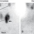
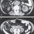
Metastases do not begin in the bone cortex but rather in the red marrow, which filters the tumor cells out of the blood. After growing within the marrow space, the lesion becomes large enough to erode the bony cortex. The most sensitive method of finding metastatic disease in the spine is MRI ( Fig. 8.38 ). Unfortunately, MRI can focus only on limited portions of the body at one time. Therefore, if you are thinking about metastatic disease to the skeleton, the most cost-effective imaging study is a nuclear medicine bone scan. If a patient has pain in a specific area and you expect a very aggressive and destructive lesion (such as from renal cell carcinoma), order a plain x-ray of the area. Multiple myeloma not only can produce focal lytic lesions but also can diffusely involve the bones, removing enough of the calcium so that all the bones become difficult to see.

If a patient has lymphoma or has a known cancer of the central nervous system, head and neck, ovary, uterus, pancreas, colon, or rectum and if the serum alkaline phosphatase level is normal and no bone pain is present, a nuclear medicine bone scan is not needed for the initial workup. Nuclear medicine bone scans on patients with other neoplasms are indicated in the following situations:
- •
Initial staging
- •
Non–small cell cancer of the lung, breast, or prostate
- •
Bone pain by history
- •
Increased serum alkaline phosphatase, calcium, or prostate-specific antigen level
- •
Follow-up if initial bone scan was positive
- •
New or worsening pain
- •
Completion of at least two cycles of chemotherapy
- •
Six weeks after completion of chemotherapy or radiotherapy, negative initial bone scan follow-up, and new pain
Unusual Lesions
A characteristic but unusual lesion of the lumbar spine is ankylosing spondylitis. It occurs primarily in young male patients (onset at about age 20 years) and sometimes is associated with ulcerative colitis. Ninety-five percent of patients are positive for human leukocyte antigen (HLA)-B27. In this disease, calcification bridges the disk spaces. This is easily seen on the lateral plain x-ray and is referred to as a bamboo spine . On the AP view, you will note fusion of the SI joints ( Fig. 8.39 ), and sometimes you can see what is known as whiskering (also called enthesopathy ) of the ischial tuberosities and along the lateral ilium. About 30% of patients will have a peripheral arthritis that spares the hands but involves the feet.

Osteoporosis and Bone Mineral Measurements
The accurate measurement of bone mineral density (BMD) with noninvasive methods can be of value in the detection and evaluation of primary and secondary causes of decreased mass. These include primary osteoporosis and secondary disorders such as hyperparathyroidism, osteomalacia, malabsorption, multiple myeloma, diffuse metastases, and glucocorticoid therapy or intrinsic glucocorticoid excess.
The largest patient population is affected by primary osteoporosis. Osteoporosis is an age-related disorder characterized by decreased mass and increased susceptibility to fractures in the absence of other recognizable causes of loss. Primary osteoporosis is generally subdivided into type 1, or postmenopausal osteoporosis, which is related to estrogen deprivation, and type 2, or senile osteoporosis, which occurs as a result of aging.
Primary osteoporosis is a common clinical disorder and a major public health problem because of the significant number of related fractures occurring annually. Because the risk for vertebral and femoral neck fractures increases dramatically as BMD levels decrease to less than 1 g/cm 2 , fracture risk in individual patients may be estimated. Furthermore, in estrogen-deficient women, BMD values may be used to make rational decisions about hormone replacement therapy and as follow-up in assessing the success of hormone replacement or specific bone-enhancing therapies.
A number of methods have been devised to permit the accurate and reproducible determination of bone mineral content. Plain x-rays generally require a loss of 30% or more of bone mineral for a change in density to be appreciated and are thus insensitive for the detection of the disease. Bone mineral measurements now are made by using dual energy x-ray absorptiometry (DEXA), which is accurate and reliable. Results are usually presented in terms of absolute BMD (g/cm 2 ) and percentiles of reference in normal young adult and age-matched populations. Normal BMD is defined as being within 1 standard deviation of the young adult mean. Osteopenia is BMD 1 to 2.5 standard deviations less than the young adult mean. Osteoporosis is a BMD more than 2.5 standard deviations below the young adult mean.
The use of bone mineral measurement has been controversial, partly because of the wide variation of measurements in the normal population. The criteria for selecting the optimal skeletal site for evaluation have not been well defined because bone mineral loss does not progress at the same rate at different body sites. In any case, the method can be used to determine the presence of osteopenia and to evaluate the effectiveness of a therapeutic maneuver by using serial scans in which the patient acts as his or her own control. Normal results, or bone mineral content in the upper portion of the normal range, define patients for whom therapy may not be needed. Indications for using DEXA are given in Box 8.3 .
Intention to use hormone replacement or other medical therapy if osteoporosis is present
Suspect low bone mineral density based on osteopenia on plain radiographs
Low-impact or nontraumatic vertebral fractures by x-ray examination in a postmenopausal woman (see text for additional factors), or in a premenopausal woman or a man with normal serum thyroid-stimulating hormone, serum calcium, alkaline phosphatase, and serum protein electrophoresis levels
Loss of height > 2.5 inches
Risk factors for low bone mineral density include estrogen-deficient state, chronic liver or renal disease, thyroxine therapy, steroid therapy for > 6 months (baseline and 12-month follow-up), hyperparathyroidism, hypogonadism in a man, and nutritional disorder
Follow-up hormone therapy (only if a change in management is being contemplated)
DEXA , Dual-energy x-ray absorptiometry.
Stress Fractures
Stress fractures are the result of (1) fatigue from repetitive stress on normal bone resulting in remodeling or (2) insufficiency fractures due to normal activity on bones that are weak. Stress fractures are particularly common in athletes, ballet dancers, and military recruits. These most commonly occur in the elbow and lower extremities. Sacral, pelvic, and vertebral stress fractures are more likely to occur in older adults and can be due to osteoporosis treatment and radiation therapy. X-rays are the initial appropriate imaging method but, with early x-rays, the sensitivity is only about 15% to 35%. As a result, some will repeat the x-rays in 10 to 14 days to see if other signs (such as periosteal reaction or sclerosis) have developed; at this time, the sensitivity is about 30% to 70%. If necessary, MRI without contrast of the area may be done. Historically, a nuclear medicine three-phase bone scan was ordered; MRI has the same sensitivity but more specificity.
Shoulder and Humerus
Normal Anatomy and Imaging
The standard view of the shoulder is obtained in an AP or PA projection, with the arm rotated internally and then externally. When the arm is in internal rotation, the humeral head looks generally smooth and spherical over the upper portion. In external rotation, a concavity of the bicipital groove is seen in the lateral aspect of the humeral head. In children, the proximal humeral epiphysis and an epiphyseal plate are visualized. This can sometimes be confused with a fracture. If the epiphyseal plate is not parallel to the x-ray beam, several lucent lines traversing the proximal portion of the humerus can be seen because the epiphyseal plate is tilted off-axis relative to the x-ray beam ( Fig. 8.40 ).

On a plain AP x-ray of the adult shoulder, the medial portion of the humeral head overlaps with the lateral aspect of the glenoid ( Fig. 8.41 ). Sometimes, the humeral head may project slightly lower or slightly higher than the center of the glenoid. Because the humerus is somewhat anterior to the glenoid, the humeral head will project high relative to the glenoid if the patient is tilted back when the image is taken. If the patient is tilted somewhat forward, it will appear slightly low. Examine the relationship of the distal clavicle to the acromion to see whether an acromioclavicular separation has occurred. In teenagers, an apophysis on the end of the coracoid process and on the acromion is seen as a thin crescentic white line and should not be mistaken for an avulsion fracture ( Fig. 8.42 ). The clavicle, scapula, and ribs should be examined for fractures and other lesions. Also, look to see whether any pathology exists in the visualized portions of the lung.


There are two other views of the shoulder that are commonly ordered. The first is called the Y view . This is done with the patient rotated somewhat so that the scapular blade is seen on edge and projects off the chest wall. The acromion, spine of the scapula, and blade of the scapula form a Y ( Fig. 8.43 ). The humeral head should normally project at or near the intersection of the three lines. This view is usually obtained if a shoulder dislocation is suspected and also is useful to look for fractures of the scapular blade.

The second view often obtained is the axillary view, in which the elbow is elevated and the beam projection is directly down through the shoulder. This allows clear visualization of the relation of the glenoid to the humeral head ( Fig. 8.44 ). Unfortunately, this view is difficult to obtain on patients who have a true dislocation. Be careful about ordering this projection if you suspect a humeral head or humeral shaft fracture because the technologist(s) may make the situation worse by elevating the patient’s elbow in an attempt to obtain the axillary view.

Plain x-rays of the shoulder are really useful only to define bony anatomy. Many shoulder injuries involve soft tissues and, for their evaluation, the most useful imaging test is an MRI scan. The joint and soft tissues also can be visualized by injecting contrast directly into the joint and imaging with MRI or CT. MRI allows excellent visualization not only of the muscle but also of the joint space and tendons ( Fig. 8.45 ). Remember that what appears to be a white bone on a magnetic resonance (MR) image is really fat within the marrow space, and the cortex of the bone is seen as a black line around the edge. Fat in the subcutaneous areas is also seen as white, and muscle is usually gray.

Acute Shoulder Pain
Acute shoulder pain can result from many causes. X-rays are the best initial imaging text. Subsequent imaging may vary, depending on the findings and suspected cause. If there is persistent significant pain and the physical examination and history are not helpful, and rotator cuff or labral tear, tenosynovitis, bursitis, or instability is suspected, MRI without contrast is appropriate. If septic arthritis is suspected, arthrocentesis is indicated.
Trauma
Box 8.4 shows the high-yield areas to examine for upper extremity trauma. Probably the three most common acute shoulder injuries are fracture, shoulder separation (acromioclavicular separation), and dislocation of the humeral head.
Shoulder
AP view
Anterior dislocation, humeral head inferior and medial
Posterior dislocation, humeral head not round and slightly lateral
Acromioclavicular separation
Clavicular fracture
Scapular fracture
Rib fracture
Y view
Dislocation
Scapular fracture
Elbow
AP view
Radial head fracture
Supracondylar fracture
Lateral view
Posterior fat pad (always abnormal)
Bulging anterior fat pad
Olecranon fracture
Coronoid fracture
Radial head alignment
Wrist
PA view
Distal radius
Ulnar styloid
Navicular
Widening between navicular and lunate
Two distinct rows of carpals present
Base of thumb
Lateral view
Alignment of radius, ulna, lunate, and distal carpals
Dorsum (for triquetral fracture)
Hand
AP view
Fifth metacarpal (boxer’s fracture)
Base of first metacarpal (Bennett or Rolando fracture if intraarticular)
Base of first proximal phalanx (gamekeeper’s thumb)
Proximal interphalangeal joints, dislocations
Distal phalanx, tuft fracture
Lateral view
Base of phalanges (volar plate fracture)
AP , Anteroposterior; PA , posteroanterior.
Fractures
Most clavicular fractures occur in the midportion or distal third of the clavicle. Usually, the fractures are clinically obvious ( Fig. 8.46 ). Rarely, dislocation of the proximal head of the clavicle from the sternoclavicular joint occurs; however, this also is clinically obvious. Fracture of the scapula is relatively rare, although it can occur as the result of a direct blow. Often, this is apparent on a routine shoulder radiograph and from the clinical history ( Fig. 8.47 ). In many cases, the fracture cannot be seen in its entirety as it traverses the blade of the scapula and, if there is any additional question, a Y view x-ray or CT scan may be useful.


Fractures of the midhumerus or proximal humerus present few problems in radiographic interpretation and thus are not considered further here.
Acromioclavicular Separation
In this injury, superior dislocation of the distal clavicle occurs relative to the acromion ( Fig. 8.48 ). Because the clavicle is slightly anterior relative to the acromion, it sometimes appears as though a separation exists when none is present if the patient is leaning back when the radiograph is taken. If you have any question, a single view that includes both shoulders often is useful. Sometimes, AP x-rays of the shoulders with the patient holding a weight in each hand are ordered to see if this will accentuate a separation, but this is rarely necessary in practice.

Dislocations
More than 95% of shoulder dislocations occur with anterior dislocation of the humeral head relative to the glenoid. This is in contrast to the hip, in which the vast majority of femoral head dislocations are posterior. In an anterior shoulder dislocation, the humeral head usually is seen to be inferior to the glenoid on the AP projection, with medial displacement of the humeral head from its normal position relative to the glenoid ( Fig. 8.49 ). As mentioned earlier, on the oblique view of the shoulder (the Y view), the humeral head should sit over the central portion of the Y. A Y view will clearly show the anterior and inferior dislocation of the humeral head ( Fig. 8.50 ).


Three specific abnormalities may be found in addition to the dislocation. As a dislocation occurs, there is sometimes a fracture of a portion of the humeral head or the glenoid. Some physicians relocate a dislocated shoulder without obtaining a prereduction image. If you do this and the postreduction image demonstrates a fracture, the patient may accuse you of being responsible for the fracture during the reduction. The second abnormality occurs in patients who have had repeated dislocations. Chronic trauma caused by interaction of the inferior edge of the glenoid with the humeral head produces a deformity or groove in the posterior lateral portion of the humeral head, known as a Hill-Sachs deformity ( Fig. 8.51 ). This is best seen on the AP view with the arm internally rotated. Another abnormality that occurs as a result of multiple anterior dislocations is a defect in the bone at the anterior inferior aspect of the glenoid rim, known as a Bankart lesion.

Posterior shoulder dislocations are rare, and they are quite tricky to identify on a standard AP view of the shoulder. Remember that with internal rotation, the humeral head on the AP projection is typically like the top half of a sphere. In a posterior shoulder dislocation, the humeral head simply does not appear to be rounded ( Fig. 8.52 ) and a slightly increased space is seen between the humeral head and the glenoid. The Y view will clearly show you the posterior dislocation.