Skeletal Trauma
Clyde A. Helms
Most of the differential diagnoses in skeletal radiology that I use are geared to be 95% inclusive, that is, the correct diagnosis will be mentioned 95% of the time. The yield can be increased by lengthening the list, but if the list gets too long, it can be unwieldy and less useful for the clinician. In trauma cases, however, being right 95% of the time is not good enough. Missing the correct diagnosis 5% of the time is unacceptable. Fractures simply should not be missed.
Before starting with specific examples, a few key points should be kept in mind concerning radiology of trauma. First, have a high index of suspicion. Every radiologist in the world has missed fractures on radiographs because they were not sufficiently attuned to the possible presence of a fracture. Often, the history is either nonexistent or misleading, and the anatomic area of concern is therefore overlooked. When in doubt, examine the patient. Orthopedic surgeons rarely miss seeing fractures on radiographs because they have examined the patient, they know where the patient hurts, and they have a high index of suspicion. Second, always get two radiographs at 90° to each other in every trauma case. A high percentage of fractures are seen only on one view (the anteroposterior or the lateral) and will therefore be missed unless two views are routinely obtained. Third, once a fracture is identified, do not forget to look at the rest of the film. About 10% of all cases have a second finding that often is as significant or even more so than the initial finding. Many fractures have associated dislocation, foreign bodies, or additional fractures, so be sure to examine the entire film.
Finally, do not hesitate to obtain a CT scan or an MR study if the plain films fail to confirm what is believed to be present clinically. MR imaging is being used more frequently as a primary imaging tool for trauma, replacing CT or radionuclide studies in cases in which the plain films are negative or equivocal. Make sure that an expensive examination such as CT or MR is truly going to affect patient care rather than just show an abnormality and then have the same treatment whether positive or negative. For example, there is no reason to do a CT scan or an MR study to find a subtle or occult fracture of the radial head in the elbow because the patient is going to have a posterior splint regardless of the results of the advanced study (assuming the patient had trauma to the elbow, has pain, and the plain film shows a displaced fat pad indicative of fluid in the joint). On the contrary, an elderly patient who has hip pain after a fall and has a negative plain film would benefit from an MR study because his treatment will depend on whether or not an occult fracture is present.
Spine
The cervical spine is one of the most commonly filmed parts of the body in a busy emergency department and can be one of the most difficult examinations to interpret. One of the most important pieces of information for the radiologist to have is the clinical history. If the patient has been involved in an automobile accident and has no neck pain, it is extremely unlikely that a fracture is present (1). So-called precautionary radiographs are not justified. On the contrary, if the plain films are negative in a trauma victim who has neck pain or neurologic deficits, obtain a CT scan.
Usually, a cross-table lateral view of the C-spine is obtained first to avoid unduly moving the patient who might have a cervical fracture. If the lateral C-spine appears normal, the remainder of the C-spine series, including flexion and extension views (if the patient can cooperate), is obtained.
What does one look for on the lateral C-spine? First, make certain that all seven cervical vertebral bodies can be visualized. A large number of fractures are missed because the shoulders obscure the lower C-spine levels (Fig. 42.1). If the entire cervical spine is not visualized, repeat the film with the shoulders lowered.
Next, evaluate five parallel (more or less) lines for step-offs or discontinuity as follows (Fig. 42.2):
Line 1 is the prevertebral soft tissue and extends down the posterior aspect of the airway; it should be several millimeters from the first three or four vertebral bodies and then moves further away at the laryngeal cartilage. It should be less than one vertebral body width from the anterior vertebral bodies from C3 or C4 to C7, and it should be smooth in its contour.
Line 2 follows the anterior vertebral bodies and should be smooth and uninterrupted. Anterior osteophytes can encroach on this line and extend beyond it and should therefore be ignored in drawing this line. Interruption of the anterior vertebral body line is a sign of a serious injury (Fig. 42.1B).
Line 3 is similar to the anterior vertebral body line (line 2) except that it connects the posterior vertebral bodies. Like line 2, it should be smooth and uninterrupted, and any disruption signifies a serious injury.
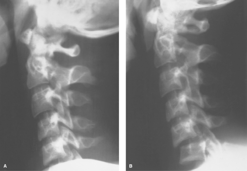
Figure 42.1. Shoulders Obscuring C5–C6 Dislocation. This patient presented to the emergency department after an injury suffered while diving into a shallow swimming pool. He had neck pain but no neurologic deficits. A. The initial radiograph of the C-spine obtained was interpreted as within normal limits. Only five cervical vertebrae are visible, however, because of high-riding shoulders. B. A repeat examination with the shoulders lowered reveals a dislocation of C5 on C6. To visualize C7, the shoulders were lowered even further. The C7 vertebral body must be visualized on every lateral C-spine examination in a trauma setting.
Line 4 connects the posterior junction of the lamina with the spinous processes and is called the spinolaminar line. The spinal cord lies between lines 3 and 4; therefore, any offset of either of these lines could mean a bony structure is impinging the cord. It takes very little force against the cord to cause severe neurologic deficits, and any bony structure lying on the cord must be recognized as soon as possible.
Line 5 is not really a line so much as a collection of points—the tips of the spinous processes. They are quite variable in their size and appearance, although C7 is consistently the largest. A fracture of one of the spinous processes, by itself, is not a serious injury, but it occasionally heralds other, more serious injuries.
After visually inspecting these five lines on the lateral C-spine, then inspect the C1–C2 area a little more closely. Make certain that the anterior arch of C1 is no greater than 2.5 mm from the dens (Fig. 42.3). Any greater separation than this (except in children, for whom up to 5.0 mm can be normal) is suspicious for disruption of the transverse ligament between C1 and C2 (Fig. 42.4).
The disc spaces are examined next to see that there is no inordinate widening or narrowing, either of which could indicate an acute traumatic injury. If a disc space is narrowed, it will usually be secondary to degenerative disease, but make certain that associated osteophytosis and sclerosis are present before diagnosing degenerative disease.
The examination of the lateral C-spine as described here can be done in less than 1 minute. If it is normal, then the remainder of the examination can be completed, including flexion and extension views. It is imperative that the patient initiate the flexion and extension without help from the technician or anyone else. A patient, if conscious and alert, will not injure himself or herself with voluntary flexion and extension and will have muscle guarding preventing motion if there is an injury present. Even gentle pressure to aid in flexion or extension can cause severe injury if a fracture or dislocation is present.
A few examples of fractures, dislocations, and other abnormalities are illustrated in the following paragraphs.
Jefferson Fracture. A blow to the top of the head, such as when an object falls directly on the apex of the skull, can cause the lateral masses of C1 to slide apart, splitting the bony ring of C1. This is called a Jefferson fracture (Fig. 42.5). It nicely illustrates how a bony ring will not break in just one place, but must break in several places. This is a rule that is seldom violated. All the vertebral rings, when fractured, must fracture in two or more places. The bony rings of the pelvis behave similarly.
CT is excellent at demonstrating the complete bony ring of C1 and shows the fractures as well as any associated soft tissue mass, much better than plain films do. In diagnosing a Jefferson fracture on plain film, the lateral masses of C1 must extend beyond the margins of the C2 body (Fig. 42.5A). Just seeing asymmetry of the spaces on either side of the dens is not enough to make the diagnosis, as this can be normally asymmetrical with rotation or with rotatory fixation of the atlantoaxial joint.
Rotatory fixation of the atlantoaxial joint is a somewhat controversial, little understood process in which the atlantoaxial joint becomes fixed and the C1–C2 bodies move en masse instead of rotating on one another. It is easily diagnosed with open-mouth odontoid views. In the normal odontoid view, the spaces lateral to the dens (odontoid) are equal. With rotation
of the head to the left, the space on the left widens, and with rotation to the right, the space on the right widens. With rotatory fixation, one of the spaces is wider than the other and stays wider even with rotation of the head to the opposite side (Fig. 42.6). This is a relatively innocuous malady that by itself is usually treated with a soft cervical collar, gentle traction, or both. Rarely it is associated with disruption of the transverse ligaments at C1–C2 (diagnosed by an increase of >2.5 mm in the space between the anterior arch of C1 and the dens); however, and when it is, it is then a serious problem. It usually
presents spontaneously or after very mild trauma such as an unusual sleeping position.
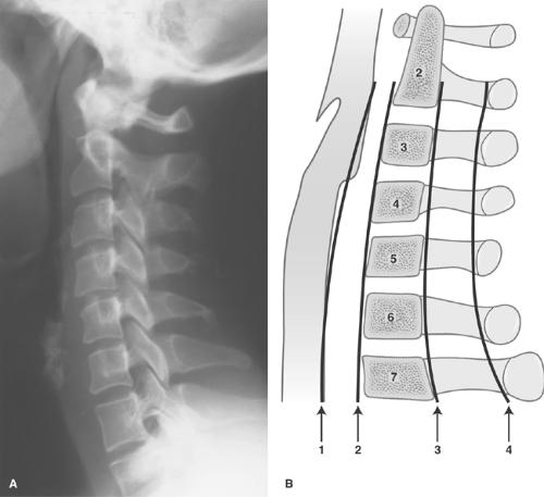 Figure 42.2. Normal Lateral Cervical Spine. A. Lateral radiograph of a normal cervical spine. B. Diagrammatic representation of a lateral C-spine showing four parallel lines that should be observed in every lateral C-spine examination. Line 1 is the soft tissue line that is closely applied to the posterior border of the airway through the first four or five vertebral body segments and then widens around the laryngeal cartilage and runs parallel to the remainder of the cervical vertebrae. Line 2 demarcates the anterior border of the cervical vertebral bodies. Line 3 is the posterior border of the cervical vertebral bodies. Line 4 is drawn by connecting the junction of the lamina at the spinous process, which is called the spinolaminar line. It represents the posterior extent of the central canal that contains the spinal cord itself. These lines should be generally smooth and parallel with no abrupt step-offs. |
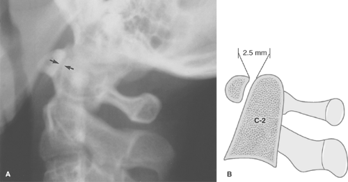 Figure 42.3. Normal C1 and C2. A lateral radiograph (A) and drawing (B) of the upper cervical spine showing the normal distance of the anteri or arch of C1 less than 2.5 mm in distance from the odontoid process (dens) of C2 (arrows). |
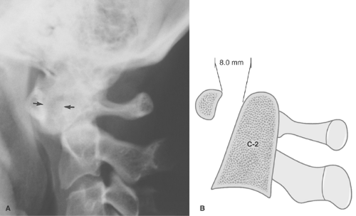 Figure 42.4. C1–C2 Dislocation. A lateral radiograph (A) and drawing (B) of the upper cervical spine in a patient who suffered trauma to the neck shows the anterior arch of C1 is 8 mm anterior to the odontoid process of C2 (arrows). This is diagnostic of a dislocation of C1 on C2 and indicates rupture of the transverse ligaments that normally hold these vertebral segments together. |
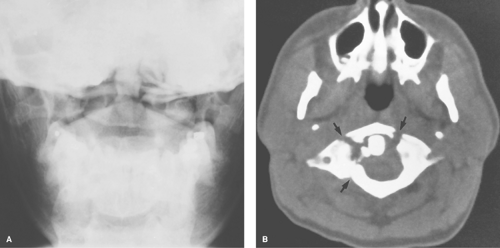 Figure 42.5. Jefferson Fracture. A. An AP open-mouth odontoid view is suspicious for the lateral masses of C1 being laterally displaced on the body of C2. Because of overlying structures, however, this is difficult to appreciate. B. A CT examination was obtained and shows multiple fracture sites in the C1 ring (arrows). This is called a Jefferson fracture. CT should be routinely used in spinal trauma because of frequent shortcomings of plain films. |
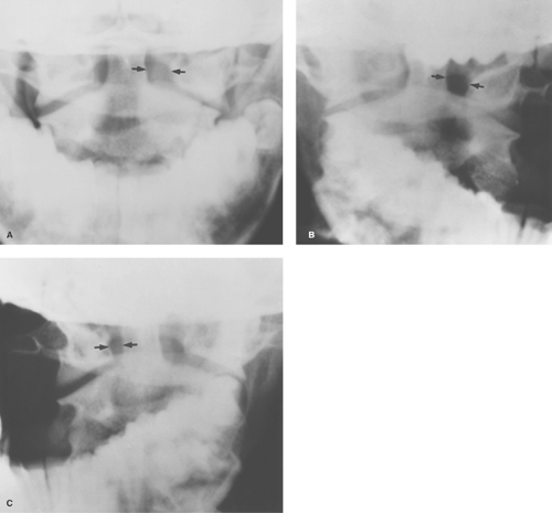 Figure 42.6. Rotary Fixation of the Atlantoaxial Joint. This patient presented to the emergency department with pain and decreased motion in the cervical spine. A. An AP open-mouth odontoid view shows the space on the left side of the odontoid between the odontoid and the lateral mass of C1 (arrows) is wider than the corresponding space on the right side. This is often the result of rotation. Therefore, open-mouth odontoid views with right and left obliquities were obtained. B. This view shows rotation of the patient’s head to the left, which causes the space on the left side of the odontoid process (arrows) to be wider than that on the right, which is appropriate. C. This view, however, shows that when the patient turns the head to the right, the space on the right (arrows) does not get wider than the space on the left. This is diagnostic of rotary fixation of the atlantoaxial joint. |
“Clay-Shoveler” Fracture. Another relatively innocuous injury is a fracture of the C6 or C7 spinous process called a “clay-shoveler” fracture. Supposedly, workers shoveling sticky clay would toss the shovel full of clay over their shoulders; once in a while, the clay would stick to the shovel, causing the ligaments attached to the spinous processes (supraspinous ligaments) to undergo a tremendous force, pulling on the spinous process and avulsing it. This can occur at any of the lower cervical spinous processes (Fig. 42.7).
“Hangman” Fracture. A “hangman” fracture is an unstable, serious fracture of the upper cervical spine that is caused by hyperextension and distraction (such as hitting one’s head on a dashboard). This is a fracture of the posterior elements of C2 and, usually, displacement of the C2 body anterior to C3 (Fig. 42.8). These patients actually do better than one might think. They often escape neurologic impairment because of the fractured posterior elements of C2 that, in effect, causes a decompression and takes pressure off the injured area.
Flexion Teardrop Fracture. Severe flexion of the cervical spine can cause a disruption of the posterior ligaments with anterior compression of a vertebral body. This is called a flexion “teardrop” fracture (Fig. 42.9). A teardrop fracture is usually associated with spinal cord injury, often from the posterior portion of the vertebral body being displaced into the central canal.
Unilateral Locked Facets. Severe flexion associated with some rotation can result in rupture of the apophyseal joint ligaments and facet joint dislocation. This can result in locking of the facets in an overriding position that, in effect, causes some stabilization to protect against further injury. This is called unilateral locked facets (Fig. 42.10). It occasionally occurs bilaterally.
“Seatbelt Injury.” “Seatbelt injury” is seen secondary to hyperflexion at the waist (as occurs in an automobile accident while restrained by a lap belt). This causes distraction of the posterior elements and ligaments and anterior compression of the vertebral body. It usually involves the T12, Ll, or L2 level. Several variations of this injury can occur: a fracture
of the posterior body is called a Smith fracture and a fracture through the spinous process is called a Chance fracture. Horizontal fractures of the pedicles, laminae, and transverse processes can also occur (Fig. 42.11).
of the posterior body is called a Smith fracture and a fracture through the spinous process is called a Chance fracture. Horizontal fractures of the pedicles, laminae, and transverse processes can also occur (Fig. 42.11).
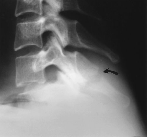 Figure 42.7. Clay-Shoveler Fracture. A nondisplaced fracture of the C7 spinous process (arrow) is noted, which is diagnostic of a clay-shoveler fracture. |
Spondylolysis. A somewhat controversial spinal abnormality that may or may not be caused by trauma is spondylolysis. Spondylolysis is a break or defect in the pars interarticularis portion of the lamina (Fig. 42.12). On oblique views, the posterior elements form the figure of a “Scottie dog,” with the transverse process being the nose, the pedicle forming the eye, the inferior articular facet being the front leg, the superior articular facet representing the ear, and the pars interarticularis
(the portion of the lamina that lies between the facets) equivalent to the neck of the dog. If a spondylolysis is present, the pars interarticularis, or the neck of the dog, will have a defect or break. It often looks as if the Scottie dog has a collar around the neck.
(the portion of the lamina that lies between the facets) equivalent to the neck of the dog. If a spondylolysis is present, the pars interarticularis, or the neck of the dog, will have a defect or break. It often looks as if the Scottie dog has a collar around the neck.
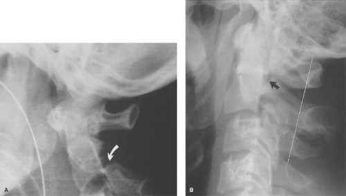 Figure 42.8. Hangman Fracture. A. Lateral films of a patient with a hangman fracture shows an obvious example of the posterior elements of the CT vertebral body fractured and displaced inferiorly (arrow). B. This view shows a very subtle fracture through the posterior elements of C2 (arrow) in another patient. A line drawn through the spinolaminar lines of the posterior elements shows the C2 spinolaminar line to be offset posteriorly in this example. |
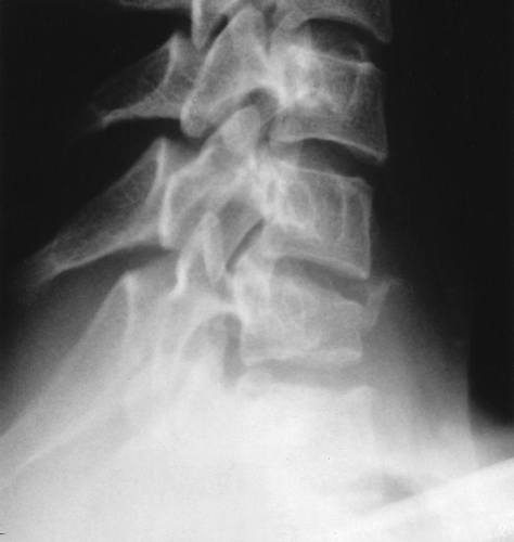 Figure 42.9. Flexion Teardrop Fracture. This patient suffered a hyperflexion injury in an automobile accident and presented to the emergency department with severe neurologic deficits. A lateral radiograph of the lower cervical spine shows wedging anteriorly of the C7 vertebral body with some displacement of the posterior vertebral line at C7 into the central canal. A small avulsion fracture off the anterior body is also noted. |
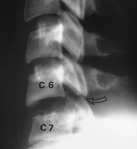 Figure 42.10. Unilateral Locked Facets. The C6-C7 disc space is abnormally widened, and the C7 vertebra is posteriorly located in relation to C6. Also note the C7 facets, which are dislocated and locked on the C6 facets (arrow). When the facets are perched in this manner, it is termed locked facets, which are unilateral in this example. |
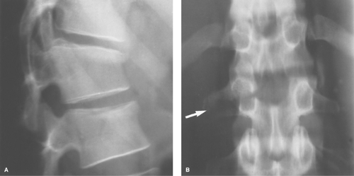 Figure 42.11. Seatbelt Fracture. Hyperflexion at the waist can cause anterior wedging of the vertebral body in the lower thoracic or upper lumbar region as shown in (A). By itself, although painful, it is somewhat innocuous; however, (B) shows a horizontal fracture through the right transverse process and pedicle (arrow) because of extreme traction during the flexion injury. When fracture of the posterior elements occurs, this injury is considered to be unstable and potentially debilitating. Any anterior wedging injury to a vertebral body should have the posterior elements of that level closely inspected. |
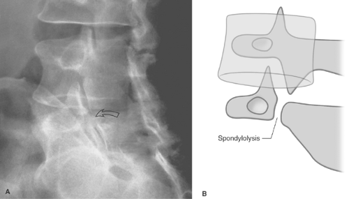 Figure 42.12. Spondylolysis. A. An oblique plain film of the lumbar spine shows a defect in the neck of the “Scottie dog” at L5 (arrow), which is diagnostic of a spondylolysis. B. A drawing of an oblique view of the lumbar spine shows how a spondylolysis appears as a “collar” around the Scottie dog’s neck. |
The cause of a spondylolysis is controversial but thought to be congenital and/or posttraumatic. Many believe this is a stress-related injury from infancy that develops when toddlers try to walk and repeatedly fall on their buttocks, sending stress to their lower lumbar spine. The significance of spondylolysis is just as controversial as its etiology. More and more clinicians are coming to the viewpoint that a spondylolysis is an incidental finding with no clinical significance in most cases. It has been reported in up to 10% of the asymptomatic population. Certainly, some patients have pain related to a spondylolysis and get relief after rest or immobilization and some with surgical stabilization. It is important to identify spondylolysis preoperatively in patients undergoing lumbar discectomy so that the possibility of clinical symptoms from the spondylolysis that can mimic disc symptoms can be evaluated. Although plain films can usually show spondylolysis, CT will show it to better advantage as well as demonstrate any associated disc
disease. Magnetic resonance will show spondylolysis, but it can be difficult to see and is easily overlooked.
disease. Magnetic resonance will show spondylolysis, but it can be difficult to see and is easily overlooked.
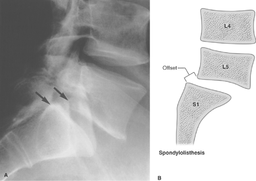 Figure 42.13. Spondylolisthesis. A. A lateral plain film of the lumbar spine shows that the L5 vertebral body is slightly anteriorly offset on the S1 body as noted by the posterior margins (arrows). B. The drawing illustrates this more clearly. Because this offset is less than 25% as measured by the length of the S1 end plate, it is termed a grade 1 spondylolisthesis. A grade 2 offset is more than 25% but less than 50% of the length of the S1 end plate. |
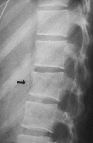 Figure 42.14. Anterior Wedge Compression Fracture. Anterior compression of this lower T-spine vertebral body (arrow) is present, which may or may not be acute. If the patient has pain in this area, it is most likely acute and must be protected with a back brace until the symptoms abate. |
If spondylolysis is bilateral and the vertebral body in the more cephalad position slips forward on the more caudal body, spondylolisthesis is said to be present (Fig. 42.13). Spondylolisthesis may or may not be symptomatic. If severe, it can cause neuroforaminal stenosis and can impinge on the nerve roots in the central spinal canal. If it is symptomatic, it can be stabilized surgically.
Anterior wedge compression fractures of the spine are commonly seen (Fig. 42.14), especially at the thoraco-lumbar junction, due to an old injury; they are passed off by the radiologist, if they are mentioned at all, as incidental findings. The problem with this is you cannot tell from a plain film if the fracture is old or new, even if degenerative changes are present (which are often not related to the fracture). If acute and left unprotected, a wedge compression fracture can proceed to delayed further collapse with resulting severe neurologic deficits (Fig. 42.15). This is called Kummell disease and typically occurs 1 to 2 weeks after the initial trauma. Multiple lawsuits have been filed against radiologists who failed to mention minor anterior wedging of a vertebral body, which went on to further collapse with associated paraplegia. All that needs to be mentioned is that a fracture is present, which is of indeterminate age and
requires clinical correlation. If the patient has pain in that location, a back brace needs to be worn until they are pain-free. Old films can help determine if it is an old fracture. If no pain is present on physical exam, it can be safely assumed to be an old fracture. It is not necessary to obtain a CT or MRI even if pain is present, because the treatment will be the same regardless of what the CT or MRI reveal. No spine surgeon will operate on a stable spine fracture without kyphosis or neurologic deficits, so the CT or MRI adds nothing but time and expense.
requires clinical correlation. If the patient has pain in that location, a back brace needs to be worn until they are pain-free. Old films can help determine if it is an old fracture. If no pain is present on physical exam, it can be safely assumed to be an old fracture. It is not necessary to obtain a CT or MRI even if pain is present, because the treatment will be the same regardless of what the CT or MRI reveal. No spine surgeon will operate on a stable spine fracture without kyphosis or neurologic deficits, so the CT or MRI adds nothing but time and expense.
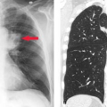
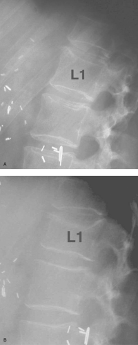 Figure 42.15. Kummel Disease. A. Very minimal anterior wedging of the L1 vertebral body is noted by comparing the height of the anterior body versus the posterior height. This patient had been in an auto accident and complained of back pain. No treatment for his back was given. B. After several weeks of continuing pain, he presents with leg weakness, which proceeded to paraplegia. A spine film now shows progression of the vertebral body collapse of L1. This almost certainly could have been avoided with simple bracing of the spine after the initial injury. |
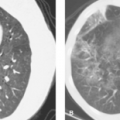
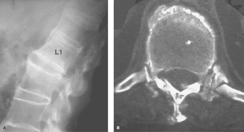 Figure 42.16. Spine Fracture in Ankylosing Spondylitis. A. A lateral spine plain film following trauma shows fusion of the spine anteriorly, which was secondary to ankylosing spondylitis. Minimal anterior wedging of the L1 vertebral body is present, which was overlooked. B. Two weeks later, a CT of the spine was performed because of the sudden onset of paralysis. This axial image through L1 shows a fracture of the posterior elements, which was undoubtedly present on the initial visit to the emergency room. Patients with ankylosing spondylitis need to be examined closely for any back pain following trauma and imaged with CT or MRI if any pain is present. |
Patients who have fusion of their spine from ankylosing spondylitis and, to a lesser extent, from DISH (diffuse idiopathic skeletal hyperostosis) are at a very high risk of spinal fractures from even relatively minor trauma. Patients with ankylosing spondylitis typically have marked osteoporosis that further magnifies their risk of fracture. A fused spine is more likely to fracture than a normal spine in a manner similar to a long glass pipette breaking more easily than a short one because it has a long lever arm. A small force at one end is greatly magnified further down the lever arm. For that reason, a patient with ankylosing spondylitis should be treated as though a spinal fracture is present if they have back pain following trauma. CT and/or MRI are mandatory if plain films are negative (Fig. 42.16).
Hand and Wrist
Several seemingly innocuous fractures in the hand require surgical fixation rather than just casting and, therefore, should be recognized by the radiologist as serious injuries.
Bennett Fracture. One such fracture is a fracture at the base of the thumb into the carpometacarpal joint, a Bennett fracture (Fig. 42.17). Because of the insertion of the strong thumb
adductors at the base of the thumb, it is almost impossible to keep the metacarpal from sliding off its proper alignment. It almost always requires internal fixation. The radiologist occasionally has to remind a nonorthopedic practitioner of this, as well as closely examine the alignment of a Bennett fracture in plaster that has not been internally fixed with wires.
adductors at the base of the thumb, it is almost impossible to keep the metacarpal from sliding off its proper alignment. It almost always requires internal fixation. The radiologist occasionally has to remind a nonorthopedic practitioner of this, as well as closely examine the alignment of a Bennett fracture in plaster that has not been internally fixed with wires.
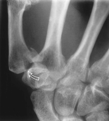 Figure 42.17. Bennett Fracture. A small corner fracture of the base of the thumb is noted, which involves the articular surface of the base of the thumb (arrow); this is a serious injury that almost always requires internal fixation. |
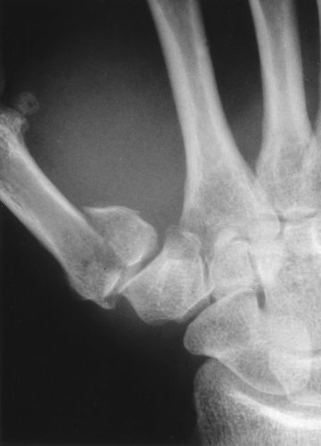 Figure 42.18. Rolando Fracture. A comminuted fracture of the base of the thumb that extends into the articular surface is a more serious type of Bennett fracture, which has been termed a Rolando fracture. |
A comminuted fracture of the base of the thumb that extends into the joint has been termed a Rolando fracture (Fig. 42.18), and a fracture of the base of the thumb that does not involve the joint has been called a pseudo-Bennett fracture.
Related posts:
Stay updated, free articles. Join our Telegram channel

Full access? Get Clinical Tree


