
History and Clinical Findings
A 23-year-old man sustained a serious head injury in a motor vehicle accident. Radiographs taken on admission (Fig. 5.1) were considered to exclude bony injuries of the cervical spine.
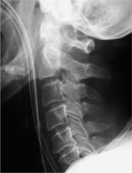
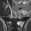
Fig. 5.1 Radiographic examination of the cervical spine in the intubated patient did not reveal any bony injuries.
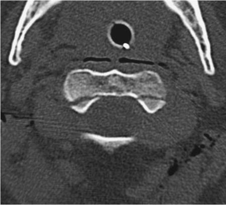
Fig. 5.2 Axial CT of the upper cervical spine on the same day shows an essentially nondisplaced fracture running through the base of the dens in the coronal plane.
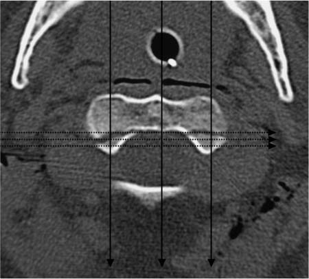
Fig. 5.3 Axial CT of the upper cervical spine. The fracture was not detected on radiographs because the beam passed through roughly equal portions of the cortex, cancellous bone, and fracture line in both the frontal projection (solid arrows) and lateral projection (dotted arrows). Consequently, the absorption differences were inadequate to permit visual detection of the fracture.
Further Case Summary
Given the severity of the cranial injuries, it was decided to include the upper cervical spine in a subsequent CT examination of the skull (Fig. 5.2). The scans revealed a fracture line running through the base of C2 in the coronal plane.
Error Analysis and Strategy for Error Prevention
Even when the CT findings were known, the dens fracture could not be identified on the cervical radiographs. This is due to the characteristics of the fracture (thin fracture line, coronal orientation, nondisplaced fragments) and the limitations of projection radiographs (Fig. 5.3). Radio-graphs are two-dimensional images that reflect the summation of x-ray absorption that occurs in a series of tissues having different densities. The fracture cannot be detected in the frontal projection because the x-rays pass equally through all portions of the vertebral body—the cortex, cancellous bone, and fracture. This summation effect does not yield a perceptible density or absorption difference between the fracture and vertebral body. The fracture was undetectable in the lateral projection for the same reason. The fracture line was thin, the fragments were minimally displaced, and the coronal orientation of the fracture resulted in insufficient image contrast for detection.
Because injuries of the upper cervical spine are not clinically apparent in up to 50% of serious-accident victims and are often missed on admission, cranial CT in all patients with serious head injuries should include scanning of the upper cervical spine. Disability resulting from a missed cervical fracture (e.g., cord impingement and paralysis caused by moving the patient before stabilizing the fracture) could have significant medicolegal consequences.
References and Further Reading
Berne JD, Velmahos GC, El-Tawil Q, et al. Value of complete cervical helical computed tomographic scanning in identifying cervical spine injury in the unevaluable blunt trauma patient with multiple injuries: a prospective study. J Trauma 1999; 47: 896–902
Davids JW, Phreaner DL, Hoyt DB, Mackersie RC. The etiology of missed cervical spine injuries. J Trauma 1993; 34: 342–345
Deliganis AV, Baxter AB, Hanson JA, et al. Radiologic spectrum of craniocervical distraction injuries. Radiographics 2000; 20: 237–250
Jelly LME, Evans DR, Easty MJ, Coats TJ, Chan O. Radiography versus spiral CT in the evaluation of cervicothoracic junction injuries in polytrauma patients who have undergone intubation. Radiographics 2000; 20: 251–259
History and Clinical Findings
A 6-year-old boy fell approximately 2 meters to the ground from a window. Afterward he complained of posterior neck pain. No other clinical abnormalities were found. Radiographs of the cervical spine in two planes showed an anterior offset of C2 relative to C3. The patient was hospitalized in the pediatric unit with a suspected ligamentous injury and dislocation at the C2–C3 level. The pediatrician requested a CT examination of the cervical spine. Because plain films taken elsewhere did not accompany the patient, the radiographic examination was repeated in pediatric radiology (Fig. 5.4). When the radio-graphs confirmed anterior displacement of the C2 vertebral body relative to C3 (approximately 2 mm on the film), CT scans were obtained of the craniovertebral junction and upper cervical spine, confirming the x-ray findings (Fig. 5.5).

Fig. 5.4a–e Radiographic examination shows a slight anterior offset of C2 relative to C3 in the neutral position (a). The vertebra occupies a normal position when the head is tilted back (b). Tilting the head forward increases the relative offset of C2 (c). There is no evidence of bony injuries.
a Lateral view in the neutral position.
b Lateral view in retroflexion.
c Lateral view in anteflexion.
d Oblique view of the right intervertebral foramina.
e Oblique view of the left intervertebral foramina.
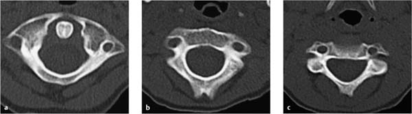
Fig. 5.5a–c Noncontrast CT scans of the cervical spine show no evidence of bony injuries.
a Axial scan at the level of C1 and the dens of C2.
b Axial scan at the C2 level.
c Axial scan at the C3 level.
Further Case Summary
A pseudodislocation at the C2–C3 level was diagnosed from the radiographs (Fig. 5.4) based on a normal position of the posterior cervical line (Fig. 5.6). There was no evidence of bony injuries or ligament instability (Fig. 5.7). When a neck brace was applied, the complaints improved within a few days and the patient was able to return to school.
Error Analysis and Strategy for Error Prevention
When an anterior offset of the posterior border of C2 relative to the posterior border of C3 is found in the neutral position in children and adolescents, it may represent a physiologic pseudodislocation or a pathologic dislocation associated with a C2 fracture (hangman’s fracture = fracture through the pedicles of the C2 vertebra). A pseudodis-location is a relatively common condition resulting from the natural compliance of pediatric ligaments. Differentiation from a true dislocation is based on the alignment of the anterior surfaces of the C1 through C3 spinous processes in the lateral radiographic view (posterior cervical line). With a pseudodislocation, the anterior surface of the C2 spinous process may deviate up to 2 mm from a line tangent to the anterior surfaces of the C1 and C3 spinous processes. If the deviation is greater than 2 mm, a true dislocation should be diagnosed (Fig. 5.6).
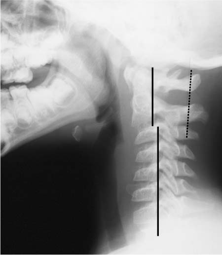
Fig. 5.6 Pseudodislocation at the C2–C3 level is evidenced by a discontinuity in the posterior vertebral body line (solid line) and a normal position of the posterior cervical line (dotted line).
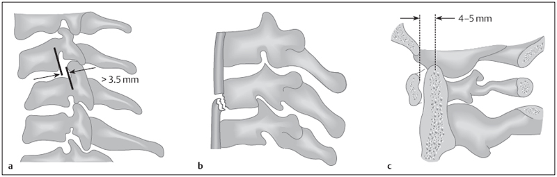
Fig. 5.7a–c Signs of instability in the upper cervical spine following trauma in adults (after Bücheler et al. 2006).
a Posterior borders of the vertebral bodies displaced by more than 3.5 mm.
b Anterior corner fracture of the vertebral body end plate.
c Increased distance between the anterior surface of the dens and the posterior border of the anterior arch of the atlas.
From a radiation safety standpoint, it would have been preferable to obtain the cervical spine radiographs taken elsewhere and merely supplement them with functional and oblique views. Based on the guidelines of the American College of Radiology, sagittal and coronal reformatted CT images and/or MRI are indicated in children and adolescents with a suspected bony and/or ligamentous injury of the cervical spine (history, clinical examination, radio-graphs). The information from both imaging modalities is frequently combined to evaluate the skeleton (CT) and the soft tissues (MRI).
References and Further Reading
American College of Radiology ACR Appropriateness Criteria. Suspected Spine Trauma. http://www.acr.org/Secondary-MainMenuCategories/quality_safety/app_criteria/pdf/ExpertPanelonNeurologicImaging/HeadTraumaDoc5.aspx (accessed November 10, 2010)
Bücheler E, Lackner K-J, Thelen M. Einführung in die Radiologie. Diagnostik und Interventionen. Stuttgart: Thieme; 2006
Greenspan A. Orthopedic Imaging: A Practical Approach. 4th ed. Philadelphia: Lippincott Williams & Wilkins; 2005
Swischuk LE. Anterior displacement of C2 in children: physiologic or pathologic. Radiology 1977; 122: 759–763
History and Clinical Findings
A 16-year-old boy was injured in a motorcycle accident while wearing a helmet, sustaining head trauma with a subdural hematoma in the right occipital area. He complained of decreased vision in the right eye. When the patient was hospitalized, CT scans of the skull and upper cervical spine were taken because clinically occult fractures of that region are common in traffic accident victims (present in approximately 20% of fatal traffic accidents) and are missed in one-half of accident survivors unless a routine CT examination is performed. In the present case an oblique, nondisplaced fracture of the dens extending from the level of the anterior atlas arch to the base of the dens was diagnosed from the CT images (Fig. 5.8). The written report stated that the anterior cortex was disrupted and the fracture margins were not sclerotic.
Two days later the cervical spine was evaluated by MRI. These images were described as showing a physiologic growth plate between the dens and body of the axis (Fig. 5.9). Additionally, the fracture line in the dens was described as subtle because of the absence of visible bone-marrow edema. There was still no evidence of displacement. A hematoma was not visible. On the basis of these findings, the most likely diagnosis was felt to be a congenital normal variant or an old fracture that had undergone fibrous union. The findings were considered atypical of a recent fracture, and further evaluation by functional MRI was recommended.
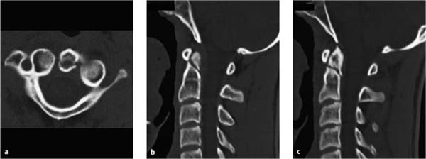
Fig. 5.8a–c CT examination of the cervical spine. The report described a fresh oblique fracture through the apex of the dens.
a Axial scan at the level of the dens.
b Sagittal reformatted image in the midline.
c Sagittal reformatted image 4 mm to the left of b.
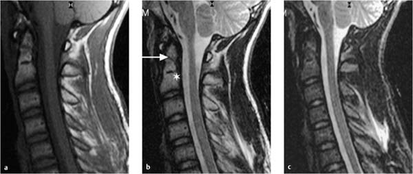
Fig. 5.9a–c MRI of the cervical spine. A physiologic growth plate was described between the dens and body of the axis (asterisk) along with a subtle fracture line (arrow). There is no evidence of displacement, bone bruising, or hematoma formation. Differential diagnosis: congenital normal variant or the fibrous consolidation of an old fracture. Edema or hemorrhagic areas are visible in the nuchal soft tissues (b, c).
a T1-weighted image without fat suppression.
b T2-weighted image without fat suppression.
c T2-weighted fat-suppressed image (STIR sequence).
Further Case Summary
The patient was treated conservatively with a cervical collar. MRI follow-up 6 weeks later showed a more conspicuous fracture line (Fig. 5.10). Even on the basis of MRI criteria, disruption of the cortex was apparent. Posterior displacement of the dens, bone-marrow edema, and hematoma formation at the fracture site had developed since the previous examination. CT scans 2 weeks later confirmed the increasing dehiscence of the fracture site and the posterior deviation of the longitudinal axis of the dens (Fig. 5.11). No signs of incipient bony consolidation were visible 8 weeks after the injury. The lesion was therefore classified as an Anderson–D’Alonzo type II fracture of the dens, subcategory B in the Eysel–Rosen classification, that was progressing to nonunion (Figs. 5.12, 5.13). Two months after the injury, the fracture was stabilized by minimally invasive internal fixation with screws and a single titanium compression plate. The surgery was uneventful. One day later the patient was feeling well and was released from the hospital.
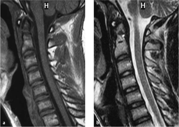
Fig. 5.10a, b MRI follow-up 6 weeks after the first examination shows slight displacement of the dens apex, gapping of the fracture line, and a new bone bruise close to the fracture site (hypointense in a, hyperintense in b).
a T1-weighted image.
b T2-weighted image.
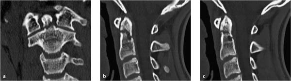
Fig. 5.11a–c CT of the cervical spine 8 weeks after the first examination shows increasing dehiscence of the fracture site and slight posterior angulation of the apical fragment.
a Coronal reformatted image.
b Sagittal reformatted image in the median plane.
c Sagittal reformatted image 4 mm to the left of b.
Error Analysis and Strategy for Error Prevention
Related posts:
Stay updated, free articles. Join our Telegram channel

Full access? Get Clinical Tree


