2 Spinal Diseases
Contents
Malformations and Developmental Abnormalities
General Pathology and Neurology
Imaging and Treatment Principles
General Pathology and Neurology
Injuries of the Cervical Spine
Injuries of the Thoracic and Lumbar Spine
Injuries of the Sacrum and Coccyx
Spinal Tumors and Tumor-like Diseases
General Pathology and Neurology
Extramedullary—lntramedullary Tumors
General Pathology and Neurology
General Pathology and Neurology
Intradural Infections and Inflammations
Extradural Infections and Inflammations
Rheumatic Diseases of the Spine
Demyelinating and Degenerative Diseases of the Spinal Cord
General Pathology and Neurology, Imaging Principles
Spinal Multiple Sclerosis and Acute Disseminated Encephalomyelitis
Other Demyelinating and Degenerative Diseases of the Spinal Cord Intradural Infektionen
Degenerative Diseases of the Spine
General Pathology and Neurology
Spondylogenic Diseases with Predominantly Radicular Symptoms
Spondylosis with Predominantly Medullary Symptoms
Disk Herniations Including Postoperative Changes and Recurrence
Other Diseases of the Spinal Column and Spinal Cord
Diseases of the Brachial Plexus
Plain Radiographs
 Basic Principles and Applications
Basically the same principles apply as in the plain radiography of craniocerebral disorders (see Chapter 1, p. 4). But compared with plain skull films, whose importance has declined markedly with the growing use of computed tomography (CT), plain radiographs of the spine have retained much of their importance as an initial imaging study, at least for the spinal column itself.

Plain radiographs of the spine are most rewarding in the diagnosis of congenital or developmental disorders, inflammatory bone diseases, extradural tumors, traumatic lesions, and degenerative diseases of the intervertebral disks and spinal joints. Plain films can also yield valuable findings in a number of polyostotic and systemic diseases.
On the other hand, it is unlikely that plain films will be rewarding in diseases that have primary or predominantly intraspinal manifestations. While biplane views (anteroposterior [AP] and lateral) are usually sufficient for the thoracic and lumbosacral regions, oblique projections and spot views are routinely obtained in the cervical spine.
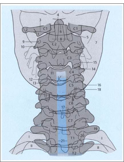
Fig. 2.1 a, b Plain films of the cervical spine (schematic): normal AP and lateral views (after Piepgras).
a AP projection.
1 Lateral mass of atlas
2 Transverse process of atlas
3 Posterior arch of atlas
4 Dens axis
5 Atlantoaxial joint
6 Anterior arch of atlas
7 Mandible
8 Maxillary teeth
9 Transverse foramen of axis
10 Right transverse process of axis
11 Superior border of C4 vertebral body
12 Inferior border of C4 vertebral body (posterior)
13 Inferior border of C4 vertebral body (anterior)
14 Inferior articular process of C3
15 Superior articular process of C4
16 Left transverse process of C5
17 Spinous process of C6 (bifid)
18 Thyroid cartilage
19 Left transverse process of T1
20 Head of first rib on left side
21 Trachea
 Survey Films, Special Views, and Tomograms
Standard views of the cervical spine. Standard radiographic views of the cervical spine start with an AP view that includes the craniovertebral and cervicothoracic junctions. If the upper cervical vertebrae cannot be clearly visualized by “blurring out” the mandible with rapid opening and closing motions of the jaw, an open-mouth view of the dens and axis should be obtained. The most important routine projection of the cervical spine is the lateral view, which should cover all of the cervical vertebrae and the craniovertebral junction (Fig. 2.1). Two oblique views are added, mainly for the purpose of demonstrating the intervertebral foramina and apophyseal joints. If necessary, the patient may be placed in a supine position for the oblique views.
Standard views of the thoracic spine. Standard projections of the thoracic spine consist of one AP view and one lateral view (Fig. 2.2). The closer a vertebra is located to the center of the image, the more accurately its shape is portrayed. The upper thoracic vertebrae are often difficult to evaluate on lateral views due to the superimposed shoulders. Oblique views seldom add useful information to the AP and lateral films.
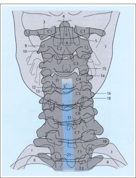
Fig. 2.1b Lateral projection.
1 Inferior border of C6 vertebral body
2 Inferior border of C6 vertebral body
3 Transverse process of C4 on one side
4 Transverse process of C4 on opposite side
5 Inferior vertebral notch of C4
6 Superior articular processes of C3, superimposed
7 Inferior articular processes of C3, superimposed
8 Spinous process of C4
9 Spinous process of C7 (vertebra prominens)
10 Sagittal diameter of spinal canal
11 C5–C6 apophyseal joint
12 Intervertebral disk
13 Dens axis
14 Anterior arch of atlas
15 Posterior arch of atlas
16 Arcuate foramen of atlas
17 Superior articular processes of atlas
18 Occipital condyles
19 Atlanto-occipital joint
20 Mastoid processes
21 Posterior borders of mandibular rami
22 Mandibular canal
23 Air column in epipharynx
24 Soft palate with uvula
25 Epiglottis
26 Hyoid bone
27 Larynx
28 Trachea
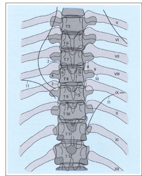
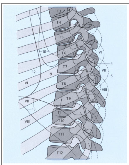
Fig. 2.2a, b Plain films of the thoracic spine (schematic): normal AP and lateral views (after Piepgras).
a AP projection.
1 Height of T8 vertebral body (between superior and inferior margins)
2 Superior articular process of T8
3 Inferior articular process of T9
4 Right transverse process of T8
5 Spinous process of T9
6 Pedicles of T8
7 T9-T10 intervertebral disk
8 Head of left eighth rib
9 Neck of left eighth rib
10 Tubercle of left eighth rib
11 Diaphragm
Fig. 2.2b Lateral projection.
1 Height of T9 vertebral body (between superior and inferior margins)
2 Superior articular processes of T9, superimposed
3 Inferior articular processes of T7
4 Transverse processes of T7
5 Spinous process of T7
6 Pedicle of T7
7 T6–T7 intervertebral disk
8 Head of eighth rib on both sides
9 T7–T8 intervertebral disk
10 Inferior borders of scapulae
11 Nutrient canal in T10
12 Posterior border of heart
13 Right and left hemidiaphragms
Standard views of the lumbar spine. Standard projections of the lumbar spine also consist of an AP and lateral view, which should include the sacrum and thoracolumbar junction (Fig. 2.3). Oblique views are usually omitted. Their main purpose is to demonstrate the posterior elements and confirm or exclude suspected spondylolysis (due to spondylolisthesis).
Special views. Special views should be obtained in cases where CT and conventional tomography are unavailable and it is important to scrutinize the posterior elements. Various special projections have been devised for the cervical and lumbar spine; they are rarely used today and are described in the specialized literature. Special views may include/unctiona/ views, which generally consist of lateral projections of the cervical or lumbar spine taken with the spinal region of interest in positions of maximum flexion and extension. These views can detect segmental and regional abnormalities of spinal alignment with hypomobility or hypermobility of vertebral segments. In principle, functional views can also be used to evaluate lateral bending. This study consists of AP projections taken with the patient bending to the right and left.
Conventional tomograms. Today there is less need for conventional tomography than before owing to the wide availability of CT. Its indications may decline further as spiral CT scanning becomes more widely utilized. Even long segments of the spinal column can be quickly analyzed with spiral CT, and three-dimensional (3-D) images can be reconstructed as needed. The use of complex tomographic motion patterns is not as critical in the spine as in cranial examinations, although linear streaking can often degrade the image quality. The examination should be done in two planes whenever possible; a slice thickness of 5mm is usually sufficient.
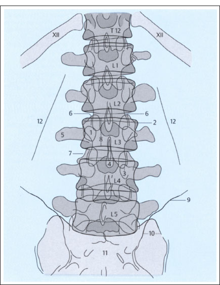
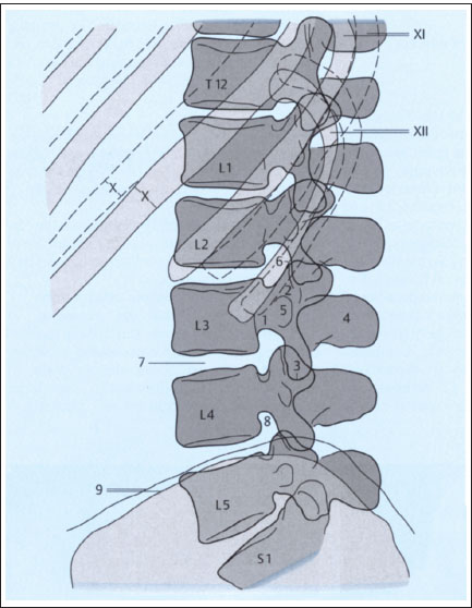
Fig. 2.3a, b Plain films of the lumbar spine (schematic): normal AP and lateral views (after Piepgras).
a AP projection.
1 Pedicle of L3
2 Superior articular process of L3 on left side
3 Inferior articular process of L3 on left side
4 Spinous process of L3
5 Transverse process of L3 on right side
6 L2–L3 apophyseal jointon right side
7 L3–L4 intervertebral disk
8 Height of L3 vertebral body (between superior and inferior margins)
8 Iliac creston left side
10 Left sacroiliac joint
11 Sacrum
12 Psoas margin
Computed Tomography
 Basic Principles and Applications
CT, which has been used increasingly for spinal examinations since 1980, is discussed more fully in the chapter on cranial imaging (see p. 8ff). Here we shall review only a few features that distinguish spinal CT from craniocerebral scanning. First, spinal CT is less suitable than cranial CT as a screening examination. If spinal magnetic resonance imaging (MRI) cannot be performed, CT is of greatest value in cases where radicular or cord symptoms are present, plain films have failed to show the cause of the symptoms, and myelography or angiography would be the next (invasive) step in the diagnostic workup. But if the level of the lesion is uncertain over a span of more than three or four segments, myelography is the more appropriate study due to the possibility of a mass lesion—particularly since negative plain and contrast-enhanced CT scans would not rule out an intraspinal lesion.
Fig. 2.3b Lateral projection.
1 Pedicle of L3
2 Superior articular processes of L3, superimposed
3 Inferior articular processes of L3, superimposed
4 Spinous process of L3
5 Transverse process of L3
6 Portion of L2–L3 apophyseal joint
7 L3–L4 intervertebral disk
8 L4–L5 intervertebral foramen (neural foramen)
9 Iliac crest on both sides
Spinal CT is most often rewarding in patients with congenital or developmental disorders, traumatic lesions, or degenerative diseases of the spine.

CT is particularly valuable in the initial assessment of spine-injured patients, as it provides a fast and reliable way to determine whether the posterior elements are intact and whether there is cord compression by bone fragments or hematoma.
It should be added that the misinterpretation of artifacts on spinal CT is a recurring problem that may prompt the use of more invasive diagnostic procedures.
 Standard and Special Techniques
Generally the patient is examined in the supine position, but a lateral or prone position can be used if needed. Scout views serve to locate the region of interest and determine the optimum scan angle; they can also provide baseline information on the spinal column.

The size of the scan field of view (FOV) or display field of view (DFOV) depends upon the desired degree of coverage of the paravertebral structures.
The choice of slice thickness is influenced by the following factors:
• Nature of the spinal region of interest,
• Presumptive diagnosis,
• Plain film findings.
It is important to realize that as the slice thickness is decreased, image contrast diminishes. At the same time, the tissues of the spine have good natural contrast, at least extradurally. A slice thickness of approximately 4mm is used for lumbosacral and thoracic scanning (Figs. 2.4,2.5) and 2mm for cervical scanning. Overlapping slices should be avoided to reduce radiation exposure.
Today spiral CT can cover long segments of the spinal column in a single pass. With proper selection of scan parameters, the acquired data can be used to reconstruct highly detailed 3-D images of the spinal column, which can be particularly advantageous in trauma diagnosis. Compared with cranial imaging, plain scans are of relatively greater importance in spinal CT. Although intravenous (i.v.) contrast administration can be used in principle for spinal scanning, the visualization of hypervascular extradural or intradural lesions (arteriovenous [AV] malformations, very vascular tumors, postdiscectomy scar, etc.) can be improved by the bolus injection of contrast medium.

It should be noted that lesions that cause disruption of the blood—spinal cord barrier, whether vascular or not, are detected with far less success intraspinally than intracranially.
Assuming adequate enhancement of the dura and the epidural venous plexus, i. v. contrast administration also improves the detection rate of cervical disk herniation.
With intrathecal contrast administration, CT can detect lesions that are missed by the methods described above. This applies mainly to extramedullary space-occupying lesions, however. With an intramedullary mass, the degree of cord expansion must be considerable before it can be recognized as pathologic. Intrathecal CT myelography is performed with a nonionic, water-soluble contrast material that has low neurotoxicity. Primary CT myelography is a procedure in which low doses of contrast medium are injected into the subarachnoid space (usually at the lumbar level), followed by CT examination of the spinal region of interest. CT following conventional myelography is known as postmyelographic CT or secondary CT myelography (Figs. 2.6, 2.7).
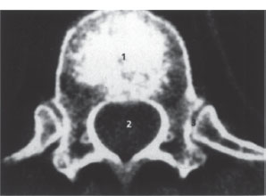
Fig. 2.4 Axial spinal CT. Scan through a thoracic vertebra; slice thickness 4mm; normal findings.
1 Vertebral body
2 Spinal canal
3 Costovertebral joints
4 Rib
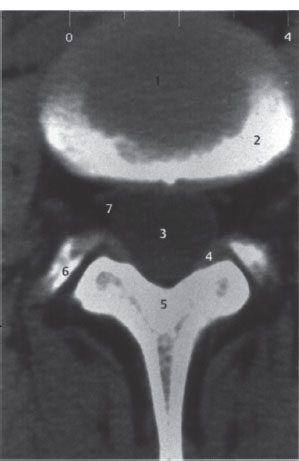
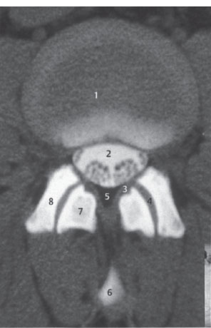
Fig. 2.5 Axial spinal CT. Scan through a lumbar intervertebral disk; slice thickness 4 mm; normal findings.
1 Intervertebral disk
2 Upper vertebral endplate, partially cut by the scan (partial volume effect)
3 Dural sac
4 Joint capsule, ligamentum flavum
5 Lamina of vertebral arch
6 Superior articular process of next lower vertebra
7 Epidural veins
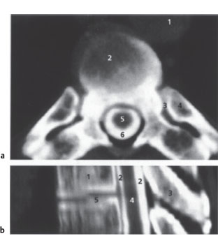
Fig. 2.6a,b CT myelography.
a Axial spinal CT after myelography (postmyelographic CT). Scan through a thoracic vertebra; slice thickness 4 mm; normal findings.
1 Aorta
2 Discovertebral junction
3 Costovertebral joint
4 Rib
5 Spinal cord
6 Contrast medium in subarachnoid space
b Postmyelographic CT of the upper thoracic region. 2-D sagittal reconstruction from axial scan data with a 2-mm slice thickness; normal findings.
1 Vertebral body
2 Contrast medium in subarachnoid space
3 Spinous process
4 Spinal cord
5 Intervertebral disk space
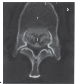
Fig. 2.7a,b CT myelography.
a Axial spinal CT after myelography (postmyelographic CT). Scan at the level of the tip of the conus medullaris. Slice thickness 4 mm; normal findings.
1 Vertebral body
2 Tip of conus with ventral and dorsal roots; contrast medium in subarachnoid space
3 Pedicle
4 Vertebral arch at base of spinous process
Fig. 2.7b Axial spinal CT after myelography (postmyelographic CT). Scan at the level of the cauda equina. Slice thickness 4mm; normal findings.
1 Intervertebral disk
2 Dural sac with nerve root; contrast medium in subarachnoid space
3 Ligamentum flavum
4 Joint space
5 Epidural fat
6 Spinous process (partial volume effect)
7 Inferior articular process of upper vertebra
8 Superior articular process of lower vertebra
 Magnetic Resonance Imaging
The basic physical principles of MRI are reviewed elsewhere in this book (see p. 13ff). Here it will be sufficient to discuss some essential methodologic aspects of spinal MRI. One is the availability of special coils designed for particular spinal segments. Only surface coils are used for imaging the lumbar and thoracic spine. Imaging of the cervical spine can use either surface coils or the volume coils that are familiar in cranial MRI.

One feature of surface coils is that the tissue is not homogeneously “illuminated,” as signal intensity decreases with distance from the coil. As a result, the subcutaneous fat layer appears disproportionately bright in all spinal images.
Phased array coils are being used increasingly in spinal MRI. Long segments of the spinal column, along with the enclosed and surrounding soft tissues, can be examined at one time with these coils with no loss of spatial resolution or image signal.
Another distinctive feature of spinal MRI is that, because of spinal anatomy, sagittal and transverse (axial) images are far more important than coronal views. In the cervical region, oblique images or corresponding reconstructions from 3-D data sets make it easier to evaluate the intervertebral foramina and their contents. Axial images directed parallel to the disk spaces can be acquired by proper selection of the imaging parameters.
Axial MR images of the spine may be degraded as a result of cerebrospinal fluid (CSF) flow and prevertebral arterial pulsations. This problem can be solved by using a special gradient pattern to suppress flow-related and pulsation artifacts [gradient moment nulling) or by applying presaturation pulses to suppress unwanted signals from structures outside the region of interest. Fat signals can be suppressed either by spectral fat saturation, which is based on the different resonant frequencies of water and fat, or by using the inversion recovery (IR) technique (short-T1 IR [STIR], see p. 17). Most of the methods for increasing image contrast mentioned on page 15 ff can also be used in the spine, especially i. v. contrast enhancement with paramagnetic contrast material (same dose). The standard slice thicknesses are in the range of 3–4mm to reduce partial volume effects and achieve adequate separation of the substructures.
Fast and ultrafast magnetic resonance (MR) sequences are of limited use in the spine. When rapid acquisition with relaxation enhancement (RARE) sequences (see p. 17) are used for axial imaging, signal voids often appear due to CSF pulsations, and flow- and pulsation-compensating sequences are not available on most MR imaging units. Echo-planar imaging (EPI) sequences (see p. 17) cannot be used for spinal imaging because the cancellous bone in the vertebral bodies causes magnetic field distortions resulting in severe image degradation.
MRI is the imaging modality of choice when cord symptoms are present, and this is also true in many patients with primary radicular symptoms. In the latter case, however, CT may be considered a more economical alternative, at least in patients with cervical or lumbar radiculopathy.

CT is always preferred in cases where information on bony structures is required (except in the medullary cavities of the spinal column), whereas MRI is superior for evaluating the intraspinal and extraspinal soft tissues.
Approaches have already been developed for spinal MRA. Fast, heavily T2-weighted sequences with fat suppression (RARE, gradient-echo [GRE] sequences) can also be used for MR myelography.
Myelography
 Basic Principles and Applications
With the more widespread use of MRI, radiographic visualization of the spinal subarachnoid space after the instillation of contrast material has become less important in the diagnosis of spinal disorders. Myelography is still an essential study in spinal emergencies (e.g., acute onset of complete cord paralysis) if an MR imaging unit is not available. Otherwise it is limited to a few specialized indications, such as standing flexion-extension views to evaluate function in patients with degenerative spinal and disk diseases. Vascular abnormalities, particularly the dilatation or increased tortuosity of medullary veins that may signify a spinal vascular malformation or dural fistula, are sometimes defined more clearly by myelography than MRI and are easier to classify as pathologic.
Another advantage of myelography is that it affords the opportunity to collect a CSF sample for laboratory analysis. The use of modern water-soluble nonionic contrast media and thin puncture needles has greatly reduced patient discomfort and complication rates.
Principal complications of myelography (extremely rare with proper technique)
 Allergies to contrast media Generalized seizures (in patients)
 Ascending meningitis
 predisposed
There is also a potential for cerebral herniation due to a rise in intracranial pressure. Spinal masses increase the risk of acute neurologic deterioration, and it may be wise in these cases to withhold myelography and rely entirely on MRI. Occasionally the puncture can cause acute spinal subdural hemorrhage with cord compression, especially in patients with coagulation disorders. Another potential problem is CSF leakage along the needle tract into the extradural tissue, upsetting the intracranial-intraspinal pressure balance and often leading to severe postmyelographic headache and autonomic dysfunction.

When proper technique is used, myelography is so well tolerated by most patients that it can be safely performed on an outpatient basis.
 Standard and Special Techniques
Three basic examination techniques are employed:
• Lumbar myelography,
• Thoracic myelography,
• Cervical myelography, which may be part of a full examination in which contrast material is instilled via lumbar puncture and allowed to flow up to the cervical region.
A recommended adjunct in many cases is postmyelographic CT, which may be combined with conventional tomography. Of the various techniques available for contrast administration, the lumbar approach is currently preferred. An 1822-gauge needle can be inserted in the sitting or prone position at low risk and with very little pain. The usual puncture site is the L2–L3 inter-space, but the L3–L4 level can also be used. Lateral puncture of the subarachnoid space between CI and C2 is recommended for selective cervical myelography. The advantage of this technique is that it requires a small amount of contrast material, resulting in fewer postprocedural complaints. The main disadvantage is the risk of injury to the spinal cord and blood vessels. In rare cases, the contrast material may have to be instilled through a suboccipital puncture site.
Lumbar myelography should be combined with standing functional views in flexion and extension whenever possible. Thoracic and cervical myelography usually employ an ascending technique, i.e., the contrast material is injected via lumbar puncture, the table is tilted to a head-down position, and the contrast is allowed to flow cephalad under fluoroscopic control. This technique will clearly demonstrate any flow obstruction within the spinal canal.

Contrast material should not be allowed to flow through the foramen magnum into the cranial vault, as generalized neurotoxic seizures may result.
The dose of contrast material depends on the nature of the examination and the iodine concentration (200—300 mg/mL) of the material used. As a general rule, more contrast material is needed for ascending thoracic and cervical myelography than for lumbar myelography. From 5–12 mL of contrast material is instilled, depending on the inquiry and the diagnostic situation. In patients susceptible to seizures, the prophylactic administration of benzodiazepine may be advised.
After standard biplane projections have been obtained (AP and lateral), oblique projections should be acquired at various angles to define the root sleeves and nerve roots. Functional views and spot views may be helpful adjuncts, depending on the clinical problem.
Cervical myelography should be supplemented by CT myelography, especially if there is major interest in defining the lower nerve roots. The shoulders can be pulled downward to eliminate artifacts and create more favorable imaging conditions. Myelography normally provides detailed views of the subarachnoid space, spinal cord, root sleeves, nerve roots, and dural sac, and the width of the spinal canal can usually be accurately determined (Fig. 2.8).

It should be noted that the lumbar roots, unlike the cervical roots, run below the pedicles of the associated vertebra.
Normal variants and anomalies should be taken into consideration, including:
• A short, stout or broadened lumbar dural sac,
• Nerve root cysts,
• Conjoined nerve roots,
• Atypical root origins,
• Bulging of the ligamenta flava.
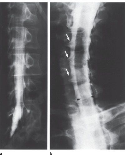
Fig. 2.8a,b Myelography.
a Lumbar myelogram. Obligue view to demonstrate the nerve roots and root sleeves. Normal findings.
b Cervical myelogram. Obligue view to demonstrate the nerve roots and root sleeves (arrows). Normal findings. The filling defect (arrowheads) is caused by the cervical cord.
Angiography
Spinal angiography requires experience with the special examination technique and a detailed knowledge of spinal vascular anatomy (Figs. 2.9, 2.10). It should be reserved for centers specializing in the technique.
Spinal angiography is generally limited to arteriography, due largely to the fact that the venous channels (the superficial veins of the spinal cord) are difficult to visualize without patients having to hold their breath. In rare cases, however, phlebography of the major veins (if necessary, with pressure measurements) or the epidural veins may be indicated.
The principal indications for spinal angiography are as follows:
• Detection or exclusion of a spinal dural AV fistula (dural fistula) or spinal AV malformation,
• Prelude to endovascular or surgical intervention for hypervascular tumors of the spinal cord or axial skeleton and before operative treatment to identify cord arteries located close to the tumor,
• Spinal angiography has no more than a “relative” indication in patients with a suspected spinal ischemic infarction, due to the difficulty of visualizing all segments of the anterior spinal artery.
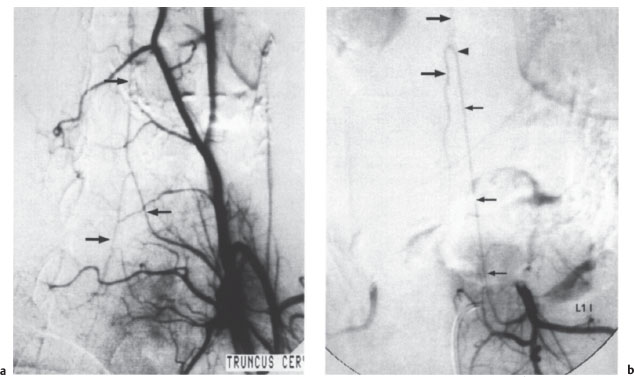
With selective angiography, radicular and spinal arteries with calibers larger than 0.2–0.4m m can be visualized. The artery of Adamkiewicz can almost always be identified at the thoracolumbar level, usually on the left side, and the anterior spinal artery can be identified in 80% of cases in the midcervical and lower cervical region (Fig. 2.11). The radicular arteries that supply the dorsal cord (posterior spinal arteries) are rarely visualized.
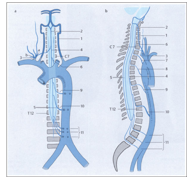
Fig. 2.9a-c Vascular supply of the spinal cord (after Piepgras).
a Anterior view.
b Lateral view.
1 Vertebral artery
2 Superior origin of anterior spinal artery
3 Thyrocervical trunk, costocervical trunk (a, b)
4 Anterior spinal artery
5 Posterior spinal arteries
6–11 Radicular arteries
10 Artery of Adamkiewicz
The current standard technique for spinal angiography is as follows:
• Selective bilateral injections of the intercostal and lumbar arteries, vertebral arteries, costocervical and thyrocervical trunk, and lumbosacral branches of the internal iliac artery using specially shaped catheters.

Catheterization should preferably be done without a guidewire, especially in the segmental arteries, to prevent vascular obstruction.
After the trial injection of 1 mL of a nonionic contrast material, 3–5 mL of contrast is administered by manual injection. Film sequences of 5–10s duration (sometimes considerably longer) are then taken to evaluate venous drainage. Survey aortography is generally not an acceptable substitute for spinal angiography.
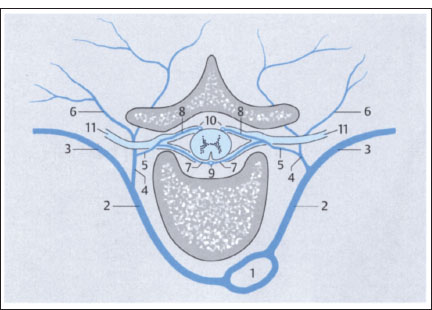
Fig. 2.9c Axial view (thoracic level).
1 Aorta
2 Intercostal artery
3 Branch of intercostal artery to chest wall
4,5 Radicular arteries (radiculomedullary arteries)
6 Muscular branches
7 Anterior branch of radiculomedullary artery
8 Posterior branch of radiculomedullary artery
9 Anterior spinal artery
10 Posterior spinal arteries
11 Spinal nerve
While lesion-centered filming of the segmental arteries is sufficient for the preoperative evaluation of tumors of the spinal cord and axial skeleton, evaluation for a dural fistula or AV malformation often requires visualizing all of the spinal arteries and their homologues in addition to the pelvic arteries.

With proper examination technique, modern spinal angiography is associated with a very low risk of complications.

Fig. 2.10 Microradiography of the arteries of the thoracolumbar cord. The cord derives most of its blood supply from the large-caliber artery of Adamkiewicz (arrow at center), which can be traced to the conus arcade (curved arrow). The arrowheads mark the anterior spinal artery, which receives an additional branch at the high thoracic level (small arrow). AP projection.
Fig. 2.11 a, b Selective spinal angiography.
a This film demonstrates the left costocervical trunk with the anterior spinal artery (arrows mark the ascending and descending branches). Normal findings; AP projection.
b This film shows the first lumbar artery on the left side and the typical hairpin configuration of the artery of Adamkiewicz (small arrows). Arrowhead marks the junction of the straight ascending branch with the tortuous descending branch (large arrows). Normal findings; AP projection.
Discography
Discography has grown in importance over recent years due to the introduction of percutaneous nucleotomy as it can determine whether the anulus fibrosus is intact or torn (a break in the anulus would contraindicate percutaneous treatment). But percutaneous nucleotomy has fallen out of favor (see p. 385), and discography has very few indications today.
Discography is an essential study prior to chemonucleolysis. It can be performed under CT as an fluoroscopic control. Discography presents few technical problems as a rule. An 18–22-gauge spinal needle is used. A posterolateral approach under continuous fluoroscopic guidance is preferred for lumbar discography.
Discography may be directly combined with lumbar myelography or a percutaneous therapeutic procedure, so that only a single puncture is needed. Cervical discography requires an anterior approach. After the needle placement has been checked radiographically, 0.5–1.5 mL of a standard myelographic contrast material is injected into the disk. Normally the contrast will not run out of the disk at the posterior vertebral margin. Contrast leakage into the epidural space confirms a sequestrum or a tear in the anulus fibrosus. Epidural contrast is best seen fluoroscopically in the lateral projection, and it can be confirmed by CT.

A rare complication is secondary discitis. Injuries to nerve roots or blood vessels are extremely rare.
Sonography
B-mode imaging is used almost exclusively for ultrasound examinations of the spinal canal.
In newborns and small children, the spinal canal and its surroundings are accessible to transcutaneous scanning since the vertebral arches are still cartilaginous.

An important indication for sonography in this age group is to identify the cause of scoliosis (neuroblastoma?).
Another clinically important indication for spinal ultrasound is a suspected tethered cord syndrome with a low position of the conus medullaris (see p. 282). Normally the conus reaches its definitive position at L1–L2 by 8–10 weeks after birth.
Ultrasound can also be used in Chiari malformation and other craniocervical junction abnormalities to determine whether the cervical cord is fixed or freely mobile. If the cord is fixed, surgical release may be indicated, and ultrasound can again be used for postoperative follow-up. Another recent application is intraoperative ultrasound used in spinal trauma cases to check the reduction of posterior marginal fragments of vertebral bodies (Fig. 2.12).
Nuclear Medicine Imaging
Basic principles, tracers, and examination technique are discussed in more detail in the chapter on cranial imaging (see p. 35).
 Planar Imaging
The following tests still employ planar technique for standard imaging protocols. The examination can be continued if necessary using the single photon emission CT (SPECT) technique.
Bone Scans
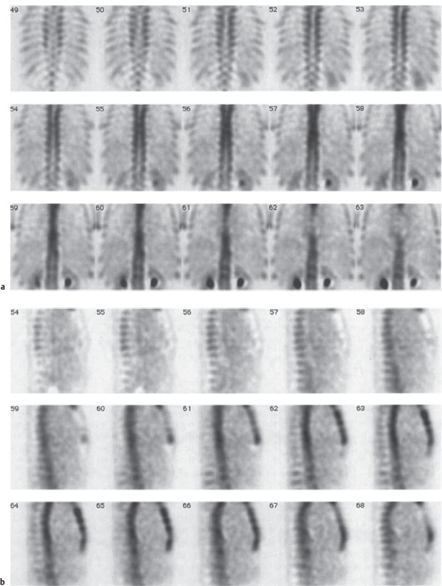
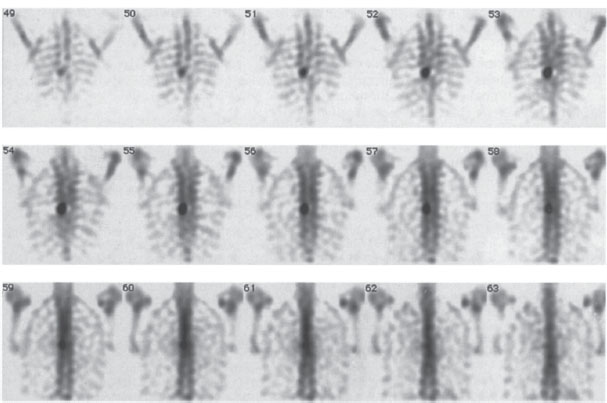
The tracer most commonly used for bone scans is 99mTc methylene diphosphonate (99mTc-MDP). The accumulation of Tc phosphates on the bone surface occurs at sites of increased osteoblastic activity. Because this activity is increased in most bone diseases, 99mTc-MDP scans have high sensitivity but low specificity (Fig. 2.13). The threephase bone scan, consisting of an early angiographic phase, a blood pool phase, and a late mineralization phase, can distinguish between acute inflammatory processes and chronic degenerative changes in bones and joints, resulting in increased specificity. Bone scans are used mainly in screening for metastases, establishing the identity of bone tumors, assessing tumor viability after chemotherapy, and locating foci of osteomyelitis and determining their activity. Bone scans are also obtained after trauma, in rheumatoid or degenerative diseases, in suspected cases of pseudoarthrosis following spondylodesis, and in patients with generalized metabolic bone disorders such as osteoporosis or hyperparathyroidism.
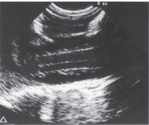
Fig. 2.12 Intraoperative spinal sonography. Longitudinal scan of the lumbar spinal canal. Normal appearance.
Inflammation Scans
Osteomyelitic conditions of the spine are imaged primarily with 67Ga-citrate. In contrast to other body regions, scans with 99mTc-labeled antibodies against peripheral granulocytes or 99mTc hexamethyl-propyleneamineoxime (99mTc-HMPAO)-labeled autologous leukocytes have low sensitivity for spinal osteomyelitis.
Bone Marrow Scans
Bone marrow scanning is done with 99mTc nanocolloid particles, which accumulate in the mononuclear phagocyte sytem (MPS) of the bone marrow, liver, and spleen, or with 99mTc-labeled antibodies against granulocyte precursors in the hematopoietic marrow, which show less uptake in the liver. The scans can define the extent of bone marrow destruction due to disseminated skeletal metastasis, plasmacytoma, or osteomyelofibrosis.
Fig. 2.13a-c Radionuclide bone scans.
a, b Normal global uptake in the spinal column with normal variations of uptake among the different vertebral elements. SPECT with 99mTc-MDP). Coronal (a) and sagittal scans (b).
Fig. 2.13c Abnormal uptake in the pedicles of a thoracic vertebral body due to metastasis from thyroid carcinoma. 99mTc-MDP SPECT; coronal scans.
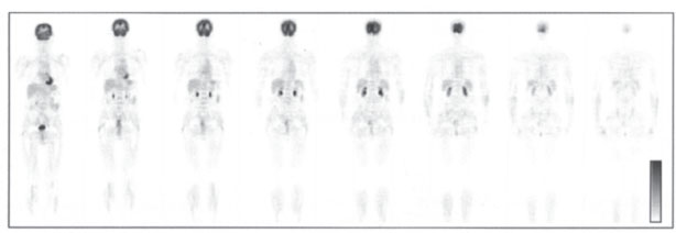
Fig. 2.14 18F-FDG whole-body PET. Coronal scans demonstrate (from anterior to posterior) normal glucose metabolism with high physiologic tracer uptake in the neurocranium, myocardium, liver, kidneys, and bladder.
 Single Photon Emission Computed Tomography
In cases where planar scans have detected abnormalities, SPECT images are often added to more accurately define location and extent. This can be done without administering additional radionuclide. SPECT provides 3-D, nonsuperimposed views of the changes.
 Positron Emission Tomography
Vertebral bodies are a frequent site of involvement by metastases from malignant tumors. Wholeor partial-body positron emission tomography (PET) scanning with 18F-deoxyglucose (18FDG) (Fig. 2.14) is a sensitive method for the detection of vertebral and extravertebral skeletal metastases. It also permits comprehensive tumor staging, including the detection of spread to parenchymal organs and soft tissues, and is useful in the diagnosis of spinal osteomyelitis. In primary bone tumors, the value of FDG-PET is still unclear.
PET scanning with 18F-sodium fluoride demonstrates abnormalities of bone mineralization, analogous to 99mTc-methylene diphosphonate (MDP) bone scans (see above). It is more sensitive and more specific than classic MDP bone scans in the detection of metastases. Disadvantages are its higher cost and its still-limited availability.
References
Amundsen, P.: Cervical myelography with Amipaque: seven years experience. Radiologe 21 (1981) 282–287
Brecht-Krauss, D. C., C. A. Guhlmann, G. Suger et al.: F-18-FDG-PET in osteitis: Comparison with immunoscitigraphy with Tc-99m-labelled monoclonal antigranulocyte antibodies. Eur. J. Nucl. Med. 23 (1996) 1067
Bury, T, A. Barreto, F. Daenen et al.: 18F-FDG PET for detection of bone metastases in patients with non-small cell lung cancer. Eur. J. Nucl. Med. 25 (1998) 1244–1247
Dublin, A. B., J. P. McGahan, M.H. Reid: The value of computed tomographic metrizamide myelography in the neuroradiologie evaluation of the spine. Radiology 146 (1983) 79–83
Eberhardt, E., H. P. Hollenbach, W. J. Huk: 3D-MR-Myelographie (3D-MRM) zur Diagnose von lumbalen Nervenwurzelkompressionssyndromen. Vergleichsstudie zur konventionellen Myelograhie. Akt. Radiol. 4 (1994) 313–317
Flannigan, B. D., R. B. Lufkin, C. McGlade, J. Winter, U. Batzdorf, G. Wilson et al.: MR imaging of the cervical spine: neurovascular antomy. Amer. J. Neuroradiol. 11 (1987) 27–32
Gratz, S., H. G. Braun, T. Behr et al.: Photopenia in chronic vertebral osteomyelitis with 99m-Tc-antigranulocyte antibody (BW250/183). J. Nucl. Med. 38 (1997) 211–216
Hammer, B.: Meningeale Spätfolgen nach lumbosakraler Myelographie mit verschiedenen wasserlöslichen Kontrastmitteln. Akt. Neurol. 4 (1977) 201–206
Höh, C. K., R. A. Hawkins, M. Dahlbom, J. A. Glaspy, L. L. Seeger, Y. Choi et al.: Whole body skeletal imaging with [18F] fluoride ion and PET. J. Comput. assist. Tomogr. 17 (1993) 34–41
Khan, A., J. A. Marc, M. Chen, J. A. Epstein: Total myelography with metrizamide through the lumbar route. Amer. J. Neuroradiol. 2 (1981) 85–90
Langlotz, M.: Lumbale Myelographie mit wasserlöslichen Kontrastmitteln. Thieme, Stuttgart 1981
Sartor, K.: Aszendierende und deszendierende Myelographie mit wasserlöslichem Kontrastmittel. Röntgen Bl. 32 (1979) 251–265
Sartor, K: Radiologische Diagnostik. In Schliack H., H. C. Hopf: Diagnostik in der Neurologie. Thieme. Stuttgart 1988
Schirrmeister, H., A. Guhlmann, J. Kotzerke et al.: Early detection and accurate description of extent of metastatic bone disease in breast cancer with fluoride ion and positron emission tomography. J. Clin. Oncol. 17 (1999) 2381–2389
Sherman, J. L., P. Y. Nassaux, C. M. Citrin: Measurements of the normal cervical spinal cord on MR imaging. Amer. J. Neuroradiol. 11 (1990) 369–372
Thron, A. K.: Vascular anatomy of the spinal cord. Springer, Berlin 1988
Malformations and Developmental Abnormalities
General Pathology and Neurology
Formation of the central nervous system (CNS) begins in the human embryo at the start of the third week of gestation with neurulation, which concludes with closure of the neural tube on day 28. Canalization and regression are important subsequent phases in the development of the spinal cord (conus medullaris and cauda equina).

Most congenital malformations occur during these three phases. The same rule applies as in other areas of embryogenesis: the earlier the defect occurs, the more severe the resulting malformation.
As a general rule, the nature of a congenital abnormality reflects the stage of development in which the abnormality occurred. In the case of an individual malformation, however, one can often postulate a variety of possible mechanisms and times of occurrence. This explains why there are several theories on the pathogenesis of spinal malformations. All are supported by experimental evidence, but none is sufficient to give a full explanation.
Classification of congenital anomalies
 Dysraphic anomalies (e.g., spina bifida)
— Open forms (spina bifida aperta)
— Closed forms (spina bifida occulta)
 Nondysraphic anomalies (e.g., Chiari malformation, sacral agenesis, congenital tumors)
The neurologic symptoms are variable. Some malformations and developmental abnormalities present with early and severe deficits, while others are often asymptomatic and are detected incidentally (lipomas, cysts, epidermoids). Some malformations, such as tethered cord syndrome, become symptomatic later in life.
The clinical manifestations of these anomalies cover the whole spectrum of spinal neurologic impairment, ranging from mild dorsal column symptoms to severe paraparesis. Spinal anomalies are commonly associated with anomalies of the axial skeleton such as scoliosis, block vertebrae, and vertebral arch defects.
Imaging and Treatment Principles
Open dysraphic anomalies are usually detected and surgically treated immediately after birth, with no need for preliminary imaging. The indication for neuroradiologie examination often arises secondarily, especially in patients who show postoperative clinical deterioration due, for example, to retethering, arachnopathy, or (secondary) syrinx formation. In all other cases the diagnostic approach is based on the nature of the clinical problem.
Magnetic resonance imaging (MRI) is the imaging modality of choice in most cases, although plain radiographs of the spine continue to play an important role. Myelography can also be a valuable adjunct in selected cases, as in patients with arachnopathy or to determine whether a spinal cyst communicates with the subarachnoid space. MRI is superior to all other modalities in its ability to delineate spinal morphology, including the intraspinal soft tissues and the internal structure of the cord. The multiplanar capabilities of MRI are particularly valuable in this regard. Recently, increased use has been made of three-dimensional (3-D) techniques in which reconstruction planes can be selected arbitrarily and tailored to the individual situation. These techniques permit an evaluation of the spinal canal that is adequate for diagnosis and treatment planning even when severe stenosis is present.
Dysraphic Anomalies
Classification of spinal malformations
 Open forms:
— Meningocele
— Myelomeningocele
— Myelomeningocystocele
 Occult forms:
— Tethered cord syndrome
— Diastematomyelia
— Lipomeningocele
— Dermal sinus
— Neurenteric cyst
 Meningocele, Myelomeningocele, and Myelomeningocystocele
These open forms of spinal dysraphism are characterized by the protrusion of spinal canal contents through a dorsal defect in the spinal column.
Meningocele. Meningoceles are skin-covered protrusions that occur predominantly in the lumbar region. Usually there is no significant neurologic impairment. MRI is ordinarily used to exclude accompanying anomalies such as a syrinx or tethered cord syndrome.
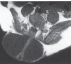
Myelomeningocele. Myelomeningoceles are usually associated with gross malformations of the spinal column and are most common in the thoracic and lumbosacral regions. Coexisting anomalies such as syrinx, dermoid, and lipoma are frequent (Fig. 2.15). In most cases there is no need to precede surgical treatment with imaging, as the risk of infection warrants immediate surgery shortly after birth. Imaging studies are often performed after the surgery, though not necessarily in the immediate postoperative period.
Myelomeningocystocele. Myelomeningocystoceles occur predominantly in the cervical and thoracic regions. They involve an enlargement of the central canal (hydromyelia) accompanied by the hernia-like outpouching of a communicating cyst. The primary neurologic deficits are mild. Myelomeningocystoceles have a high association with anomalies of the spinal column and urogenital malformations. The imaging procedure of choice is MRI.
Fig. 2.15 Lumbar myelomeningocele. The low, dysplastic spinal cord passes through a CSF-filled sac located outside the spinal canal. The cord is adherent posteriorly to the skin and subcutaneous tissue. T1-weighted axial MRI.
 Tethered Cord Syndrome
This condition is based on a failure of normal ascent of the spinal cord relative to the spine, resulting in a tethered cord (low position of the conus medullaris) with fixation of the cauda equina. The filum terminale is thickened and adherent at the lumbosacral level (Fig. 2.16).
Tethered cord can be difficult to diagnose clinically. Patients often describe subjective bladder dysfunction and leg weakness, but neurologic and urologic findings remain normal for some time, possibly leading to an erroneous psychiatric diagnosis between age 20 and 30.
MRI will usually establish the diagnosis, and myelography can be useful if doubt persists.
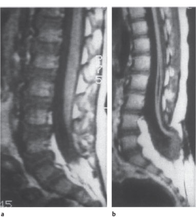
Fig. 2.16a,b Tethered cord syndrome.
a The otherwise normal-appearing conus medullaris is fixed posteriorly at the L4–L5 level. T1-weighted sagittal MRI.
b In another patient, the spinal cord and conus medullaris appear markedly narrowed. The conus terminates at the L4–L5 level in a dysraphic anomaly involving the bone and soft tissues. The lower part of the malformed, atrophic spinal cord contains a syrinx. Note also the expanded width of the lower lumbar canal and the lipoma-like increase in epidural fat.
Diastematomyelia refers to a generally sagittal division of the spinal cord into two hemicords separated by connective tissue or by a cartilaginous or bony spur. The spinal cord above and below the anomaly is normal.

Diastematomyeli a is distinguished from diplomyelia, which is a true congenital duplication of the spinal cord.
Each of the two hemicords in diastematomyelia has its own pia and arachnoid, arid each has dorsal and ventral roots on one side. The anomaly occurs predominantly in the thoracolumbar region and is associated with bony abnormalities such as scoliosis, block vertebrae, or butterfly vertebrae. Neurologic symptoms are often absent or are manifested relatively late.
The diagnostic method of choice is MRI, with coronal and axial imagesyielding more information than sagittal images. If the spinal canal is partitioned by a bony spur, the bone may contain a medullary cavity that shows fat signal intensity on T1-weighted images.
 Lipomeningocele
Spinal lipomas can occur in isolation (as hamartomas), but are more commonly associated with other malformations of the spinal cord and its coverings, especially tethered cord syndrome. Lipomeningoceles are lumbosacral dysplasias that are characterized by:
• Vertebral arch defects,
• Low conus medullaris,
• Spinal cord dysplasia.
There is local fixation of the cauda equina by an intraspinal lipoma, which communicates with a subcutaneous lipoma through the arch defect and is accompanied by a meningocele.
 Dermal Sinus
A dermal sinus is a fistula-like tract, usually epithelialized, between the skin surface and spinal canal that terminates at the epidural or subdural level and may communicate with the spinal cord. It is often associated with spinal malformative tumors such as dermoid cysts, which communicate with the body surface via the sinus tract. The most common site of occurrence is the lumbosacral region, followed by the craniovertebral region.

The sinus tract creates a potential portal for infection, with risk of meningitis.
The imaging procedure of choice is MRI.
 Neurenteric Cyst
Neurenteric cysts result from an error of embryogenesis in which a connection is established between the mesoderm and ectoderm. There is a combination of gastrointestinal and neural anomalies, including fistulae between the spinal canal and bowel or prevertebral and retrovertebral cysts and diverticula that are lined with intestinal epithelium. Other cysts may be entirely intraspinal. The most common location is the cervical region. Neurenteric cysts can be difficult to distinguish from arachnoid cysts by neuroimaging, but the latter are more commonly located in the thoracolumbar region.
Other spinal malformations can accompany neurenteric cysts:
• Wedged vertebrae,
• Butterfly vertebrae,
• Kyphoscoliosis.
MRI is the most informative study. Myelography and postmyelographic computed tomography (CT) may also be necessary in some cases to demonstrate the connection with the subarachnoid space.
Nondysraphic Anomalies
Nondysraphic anomalies of the spine include the following:
• Malformations of the spinal column:
—Congenital spinal stenosis (almost always present in achondroplasia)
—Idiopathic scoliosis
—Sacral agenesis
• Other malformations of the axial skeleton:
—Klippel—Feil syndrome
True spondylolysis in spondylolisthesis is occasionally added to this list, although it is more an acquired disorder (stress fracture) than a congenital anomaly.
Intramedullary cavitation can have various causes. Hydromyelia refers to a congenital dilatation of the central canal. Syringomyelia can have various forms:
• A primary form of unknown cause,
• Secondary forms like those occurring with tumors or after trauma.
It is unclear whether primary syringomyelia, or syringohydromyelia, should be interpreted as an isolated anomaly or simply the result of another, unknown disorder. Efforts to resolve this question have been unsatisfactory. The frequent association of a syrinx with a type I or II Chiari malformation is striking. The cavitation may be limited to the cervical cord, sometimes extending into the medulla oblongata (syringobulbia), or it may involve the thoracic cord or even the entire spinal cord. The cavity may be open or septated in its upper and lower portions, and it may expand the spinal cord or cause no apparent change in the cord diameter.
Frequent clinical findings are:
• Disturbance of pain and temperature sensation,
• Muscular atrophy in the hands,
• Autonomic dysfunction,
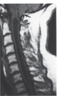
Fig. 2.17 Cervical syringohydromyelia with cavitation from C1-D1. There is a coexisting type I Chiari malformation (arrow). T1-weighted sagittal MRI.
• Spasticity,
• Osteolytic lesions,
• Neurogenic arthropathies.
A syrinx may also remain asymptomatic for some time. The diagnosis is readily established by MRI (Fig. 2.17). Today there is generally no need for other imaging studies, including myelography and postmyelographic CT.
During the examination, care should be taken to define the extent of the lesion, detect associated anomalies, and exclude a neoplasm (astrocytoma, hemangioblastoma).
 Congenital Tumors
The following are the most important congenital tumors that involve the spine:
• Dermoids
• Epidermoids
• Teratomas.
Association with other (dysraphic) disorders is relatively common.
The diagnosis is established by MRI. The signal characteristics of these tumors are very similar to those of congenital brain tumors (see p. 97). Dermoids are isointense on T2-weighted images and hyperintense on T1-weighted images (fat component) in relation to normal cord tissue. Epidermoids have a signal intensity similar to cerebrospinal fluid (CSF), and teratomas have a variable appearance due to their varying composition.
 Anomalies and Malformations in Neurofibromatosis
Besides tumors, consisting mainly of meningiomas and gliomas, neurofibromatosis may be associated with dysplastic bony changes in the spine including kyphoscoliosis and wedged vertebrae. Meningoceles can also occur; some are large and most extend into the posterior mediastinum on the right side.
Imaging studies consist of plain radiographs and especially MRI, which should be used with paramagnetic contrast enhancement to avoid missing small neurinomas.
Agnoli, A. L., A. Laun, R. Schönmayr: Enterogenous intraspinal cysts. J. Neurosurg. 61 (1984) 834–840
Barnes, P. D., P. D. Lester, W.S. Yamanashi, J. R. Prince: Magnetic resonance imaging in infants and children with spinal dysraphism. Amer. J. Neuroradiol. 7 (1986) 465–472
Davis, P., J. C. Hoffman, T. I. Ball, J. B. Wyly et al.: Spinal abnormalities in pediatric patients: MR imaging findings compared with clinical, myelographie, and surgical findings. Radiology 166 (1988) 679–685
Diebler, C., O. Dulac: Pediatric Neurology and Neuroradiology. Springer, Berlin 1987
Gerlach, J., H. P. Jensen: Mißbildungen des Rückenmarks. In Olivecrona H., W. Tönnis, W. Krenkel: Handbuch der Neurochirurgie, Bd. VII/1. Springer, Berlin 1969
Hilal, S. K., D. Marton, E. Pollack: Diastematomyelia in children: radiographic study of 34 cases. Radiology 112 (1974) 609–621
James, H. E., M. Oliff: Computed tomography in spinal dysraphism. J. Comput. assist. Tomogr. 1 (1977) 391–395
Langman, J.: Medizinische Embryologie. Thieme, Stuttgart 1980
Naidich, T. P., D. G. McLone, S. Mutluer: A new understanding of dorsal dysraphism with lipom a (lipomyeloschisis): radiologic evaluation and surgical considerations. Amer. J. Neuroradiol. 4 (1983) 103–116
Traumatic Lesions
General Pathology and Neurology
Fractures and dislocations account for a large percentage of spinal injuries that are associated with significant neuroradiologie findings. The most commonly affected vertebrae are C2, C5, C6, and C7 in the cervical spine, T12 in the thoracic spine, and L1 and L2 in the lumbar spine. Another, less frequent site of predilection is in the midthoracic spine. Males sustain two to three times more vertebral injuries than females, and persons between age 20 and 40 are at greatest risk.

Patients with strong suspicion of a cervical spine injury should be examined supine in a neutral head position.
Multiple injuries of the spinal column occur in at least 10% of cases and generally involve adjacent segments. Involvement of the spinal cord or nerve roots occurs in approximately 20% of serious spinal injuries, most commonly affecting the lower cervical and midthoracic regions and the thoracolumbar junction. Unfortunately, neural involvement sometimes results from faulty procedures during the retrieval, transport, and initial examination of trauma patients. Attention should be given to extraspinal associated injuries, including those that may require priority treatment.
The potential mechanisms of injury are complex and diverse. On the whole, indirect violence to the spine is far more common than direct violence. Hyperflexion is the most common mode of injury and may be combined with lateral flexion. This mechanism causes anterior compression and wedging of the vertebral body accompanied by posterior distraction, which may rupture the posterior ligaments. Hyperextension is usually important only in the cervical region, where it can cause tearing of anterior ligaments with avulsion fractures of vertebral bodies and possible vertebral arch fractures. Axial compression (impaction) rarely occurs in isolation and is generally one component of a hyperflexion injury. Moderate compression leads to a depressed fracture, particularly when bone strength is compromised as a result of systemic disease. Massive vertebral compression leads to burst fractures of the vertebral bodies, often with the displacement of fragments into the spinal canal. Following traumatic rupture of the anulus fibrosus, portions of the intervertebral disk can protrude into the spinal canal, creating an intraspinal mass (traumatic disk herniation). In some cervical and thoracolumbar injuries, distraction (tension) on the spinal column is the critical biomechanical factor. If the distraction is severe enough, it can cause ligament ruptures and transverse vertebral fractures. Hyperrotation is involved in many spinal injuries and is usually combined with hyperflexion. Common outcomes are injuries to posterior vertebral elements and unilateral dislocations. Shearing injuries, in which the traumatizing force is directed across the spinal column, lead to vertebral dislocations and ligamentous ruptures.
Impression of the spinal cord or cauda equina fibers is most likely to occur when vertebral fragments are displaced into the spinal canal or when the spinal canal is narrowed due to vertebral dislocation. Space-occupying hemorrhages are much less common in the spinal canal than in the cranial cavity. Radiculopathy is most likely to follow cervical spinal trauma when the neural foramen is already narrowed by degenerative osteophytes; a fracture need not be present. Other causes of cervical root compression are traumatic disk herniations and narrowing of intervertebral foramina by fragments or by dislocation with facet locking.
Imaging Principles
A selective imaging workup of presumed vertebral injuries should be undertaken only after the patient’s vital functions have been stabilized. The initial study generally consists of plain films. Repositioning should be avoided whenever possible, continuing the principles applied during transport, to avoid causing secondary vertebral or fragment displacement that might induce neurologic impairment or aggravate existing impairment.
If plain film findings look suspicious, if vertebral injuries are detected, or if root or cord symptoms are present, further evaluation by sectional imaging procedures is advised. If bony abnormalities have been detected, computed tomography (CT) is considered the best sectional modality at the present time. In many cases it offers additional advantages when used in the spiral mode, including the option for three-dimensional (3D)reconstructions. While 3-D images do not actually increase the amount of diagnostic information, they can provide a better visual impression of the pathology. The main advantage of CT is that it shows bone and soft tissues, although it is greatly limited in its ability to demonstrate intraspinal soft tissues. Conventional tomography has a role in the diagnosis of spinal trauma only if a CT scanner is not available.
Because of the low contrast resolution of CT within the spinal canal, magnetic resonance imaging (MRI) is also being used increasingly in the acute diagnosis of spinal injuries and especially to detect cord changes such as edema, hemorrhage, or transection. With vertebral dislocation or the displacement of bone fragments into the spinal canal, MRI can help determine whether the cord is compressed and define the degree of compression that has occurred. With meticulous technique, MRI can also detect injuries to the nerve roots and root sleeves.
The use of myelography and postmyelographic CT has dwindled to only a few indications, such as the investigation of radicular symptoms.
Angiography is indicated only if there is suspicion of a serious vascular injury (e.g., to the vertebral artery). It may then be necessary to proceed at once with an endovascular therapeutic procedure in selected cases.

From a clinical standpoint, it is important to distinguish stable
Stay updated, free articles. Join our Telegram channel

Full access? Get Clinical Tree


