Spinal Instrumentation
The goals of spinal instrumentation are to provide stability, reduce deformity by restoring and improving anatomic alignment, and reduce pain. Spinal instrumentation techniques have expanded dramatically over the last decade. Fixation devices are designed for the cervical, thoracic, and lumbosacral spine using a variety of surgical techniques involving anterior, posterior, transverse, and combined approaches. In most cases, bone grafting is also performed because instrument failure will eventually result if solid bony fusion is not obtained.
Imaging plays an important role in pre- and postoperative imaging of patients who may be candidates for surgical intervention. Postoperative imaging is particularly important to determine the position of the implants, follow bone graft incorporation or fusion, and to define potential complications. It is critical that radiologists be familiar with surgical techniques, the normal appearance of spinal instrumentation devices, and potential complications associated with the different procedures. Proper use of imaging techniques and knowledge of their advantages and limitations are essential for optimal patient care.
This chapter will focus on spinal instrumentation, including diagnosis, basic clinical data, and imaging of common conditions including scoliosis, trauma, degenerative disease, and spondylolisthesis. Treatment of malignant conditions will be included in Chapter 14.
Suggested Reading
Berquist TH. Imaging of the postoperative spine. Radiol Clin North Am. 2006;44:407–418.
Scoliosis
Scoliosis is a spinal deformity that can result in complex rotational and lateral curvature of the spine. Deformities may involve isolated or multiple segments. Scoliosis may be congenital (usually vertebral anomalies from birth), idiopathic (infantile, juvenile, or adolescent) or occur in adults following skeletal maturity. Idiopathic adolescent scoliosis is the most common form and is felt to be inherited with incomplete penetrance. Table 3-1 summarizes the etiologies of scoliosis.
Table 3-1 ETIOLOGY OF SCOLIOSIS | |||||||
|---|---|---|---|---|---|---|---|
|
Idiopathic Scoliosis
Infantile scoliosis
Aged 3 years or younger
More common in males
Left curve most common
Curve <30 degrees usually resolve
Curves with the progressive form have >70-degree curve by age 10
Significant curves may cause cardiorespiratory compromise
Juvenile scoliosis
More common in females
Right curve is more common
Curve progression more common than infantile
Adolescent scoliosis
Occurs at or near onset of puberty
Includes idiopathic scoliosis diagnosed after age 10
Curve must be >10 degrees
Occurs in 2% to 3% of children in the age-group of 10 to 16 years
Family history in 15% to 20% of cases
Curves <30 degrees at maturity usually do not progress
Treatment more often required in females
Adult scoliosis
Scoliosis occurring after maturity
Multiple etiologies (Table 3-1)
Thoracic curves most often treated
Curve progression and pain are indications for surgery
Congenital scoliosis
Commonly caused by vertebral anomalies (Table 3-1)
Unilateral bars progress most rapidly
Prognosis also less favorable for multiple hemivertebrae
Other organ anomalies are not uncommon
Lumbar curves more commonly associated with genitourinary and lower extremity anomalies
Thoracic curves more often associated with cardiac anomalies
Clinical Features
Scoliosis is relatively common and 70% to 80% of cases are idiopathic. Therefore, school screening has been performed across the country for quite some time. On examination, there is back asymmetry and there may be a noticeable deformity of the ribs. There may also be tilt of the shoulders and/or pelvis. Clinical curve measurements of >10 degrees are considered significant.
Measured on radiographs, curves of <10 degrees are not considered scoliosis. Two percent to 3% of children in the age-group of 10 to 16 will have scoliotic curves >10 degrees. The male to female ratio is approximately equal with smaller curves. However, measurements of >30 degrees are much more common in females. Whether curves progress depends on growth potential and specific curve patterns to be discussed later. Curve changes tend to be most significant during growth spurts. Curves ≤30 degrees typically do not progress after skeletal maturity. However, larger curves frequently progress into adulthood. Curves from 10 to 30 degrees should be followed approximately every 6 months as progression tends to occur at approximately 1 degree per month. Radiographic measurements may normally vary by 4 degrees due to human error. Therefore, the 6-month rule was established to more accurately evaluate curve progression.
Progressive curvature may result in significant cosmetic deformity and secondary effects on other organ systems such as the heart and lungs. Current treatment options include observation for small curves, electrical stimulation, braces, and surgical intervention. Curves of 30 to 50 degrees are initially treated conservatively with braces to reduce progression. Curves >50 degrees generally require surgical intervention.
Suggested Reading
Berquist TH, Currier BL, Broderick DF. The spine. In: Berquist TH, ed. Imaging atlas of orthopaedic appliances and prostheses. New York: Raven Press; 1995:109–215.
Connolly PJ, Von Schroeder HP, Johnson GE, et al. Adolescent scoliosis. J Bone Joint Surg. 1995;77A:1210–1215.
Jarvis JG, Greene RN. Adolescent idiopathic scoliosis. J Bone Joint Surg. 1996;78A:1707–1713.
Lonstein JE. Scoliosis: Surgical versus nonsurgical treatment. Clin Orthop. 2006;443:248–259.
Oestreich AE, Young LW, Poussaint TY. Scoliosis circa 2000: Radiologic imaging perspective. I. Diagnosis and pretreatment evaluation. Skeletal Radiol. 1998;27:591–605.
Scoliosis Terminology
Compensatory curve: A secondary curve located above or below the structural curve; develops to maintain body alignment
Decompensation: Loss of the spinal balance when the thoracic cage is not centered over the pelvis
Dextroscoliosis: Curve convexity is to the right
Double curve: Two curves in the same spine
Functional curve: Nonstructural or correctable by active or passive lateral bending or corrects when in the supine position
Kyphoscoliosis: Structural scoliosis associated with round back deformity
Kyphosis: Posterior convex angle of the spine seen in the sagittal plane
Levoscoliosis: Scoliosis with curve convex to the left
Lordoscoliosis: Lateral curvature of the spine associated with swayback
Lordosis: Anterior curvature of the spine in the saggital plane
Lumbar curve: Spinal curve with the apex between L1 and L4
Lumbosacral curve: Lateral curve with the apex at L5 or below
Major curve: Structural
Minor curve: Nonstructural curve
Nonstructural curve: Curve that is not fixed
Primary curve: First or earliest curve to appear
Scoliosis: Lateral curvature of the spine >10 degrees on radiographs
Structural curve: Lateral curve that is fixed
Thoracic curve: Lateral curve with apex between T2 and T11
Thoracolumbar curve: Lateral curve with the apex at T12 or L1
Suggested Reading
Dangerfield PH. The classification of spinal deformities. Pediatr Rehabil. 2003;6:133–136.
Oestreich AE, Young LW, Poussaint TY. Scoliosis circa 2000: radiologic imaging perspective. I. Diagnosis and pretreatment evaluation. Skeletal Radiol. 1998;27:591–605.
Scoliosis Research Society. Definition of Scoliosis Terms. 2007.
Classification/Curve Measurements
Scoliosis may be classified by age of onset, underlying pathology, anatomic involvement, or curve patterns. For the purpose of this discussion, the focus will be on classifications systems and measurements. There are multiple measurement approaches to include curve and rotational deformities. The Cobb method is most commonly used to measure curves and can be applied to single, double, or triple curves.
Cobb Measurement Method
Select upper and lower end vertebrae; vertebrae directed maximally to the concavity of the curve
Vertebrae included have widened disc spaces on the convex side
Lines are drawn along the most superior and inferior endplates or pedicles of the selected end vertebrae (see Fig. 3-1)
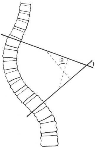
Fig. 3-1 Cobb method for measuring spinal curves. Lines are drawn along the upper vertebral margin or pedicles of the superior end vertebra and lower margin or pedicle of the inferior end vertebra. For larger curves the lines may cross giving the angle (1), for smaller curves lines are drawn perpendicular to the end vertebral lines to provide the angle (2).
For large angles the lines may cross; for smaller angles, lines are drawn perpendicular to the end vertebral lines to form the angle
Rotational Measurements
Use apex vertebra in the curve and determine the position of the pedicles or spinous process (see Fig. 3-2)
Pedicle method is preferred
Kyphosis Measurements
The end vertebrae that are maximally directed to the convexity are selected
Lines are drawn along the superior end plate of the upper end vertebrae and inferior endplate of the lower end vertebrae (see Fig. 3-3)
For large curves the lines will cross
For smaller kyphotic deformities lines are drawn perpendicular to the end vertebral lines resulting in the measurement
King Classification
Useful for predicting extent of spinal fusion; it is two dimensional and ignores sagittal profile. There are five curve categories, which are as follows.
Type I: “S” shaped with both thoracic and lumbar curves crossing midline; lumbar more severe and thoracic more flexible (see Fig. 3-4A)
Type II: Similar to type I except that thoracic curve is larger (Fig. 3-4B)
Type III: Lumbar curve does not cross the midline and is centered over the sacrum (Fig. 3-4C)
Type IV: Long thoracic curve with L5 centered over the sacrum and L4 tilted to the thoracic curve (Fig. 3-4D)
Type V: Double thoracic curve with T1 tilted to the concavity of the upper curve, which is structural (Fig. 3-4E)
Lenke Classification
Defines six curve types with modifiers for the lumbar spine in the frontal plane and thoracic spine in the sagittal plane
Lumbar modifier: Based on relationship of apex of the curve to central vertical sacral line (CVSL) (see Fig. 3-5) A-minimal lumbar curve, B-moderate lumbar curve, C-large lumbar curve
Thoracic modifier: Based on the sagittal curve measurement from T5-12 minus curve of <+10 degrees, neutral curve of 10 to 40 degrees, positive curve of >+40 degrees (see Fig. 3-6)
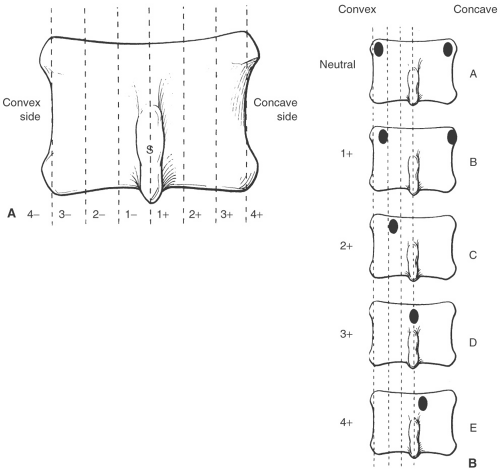
Fig. 3-2 Rotational measurements. A: Spinous process method. The vertebral body is divided into six segments (vertical broken lines). Neutral is used when the spinous process is midline. Positive is used for rotation toward the concavity and negative toward the convexity of the curve with grading from 1 to 4. B: Pedicle method. A—pedicles in normal position, B—right pedicle moves toward the midline and left at vertebral margin, C—right pedicle moves closer to midline and left not seen, D—right pedicle at midline and left not seen, E—right pedicle beyond the midline and left not seen.
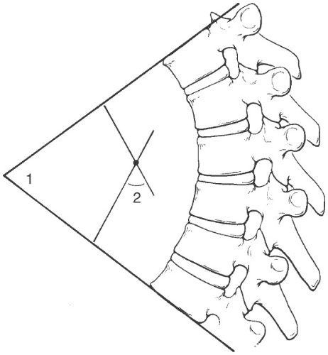
Fig. 3-3 Kyphosis measurement. The upper and lower end vertebrae are selected in a manner similar to scoliosis measurements. Lines are drawn along the endplates. For larger angles the line may cross (1), for smaller angles perpendicular lines are drawn to the end vertebral lines resulting in the measurement (2).
Type 1: Main thoracic—main thoracic curve is the major curve and proximal thoracic and thoracolumbar curves are minor or nonstructural
Type 2: Double thoracic—main thoracic curve is major curve, the proximal thoracic curve is minor and structural, and the thoracolumbar curve is minor and nonstructural
Type 3: Double major—main thoracic and thoracolumbar curves are structural, whereas the proximal thoracic curve is nonstructural
Type 4: Triple major—proximal, main thoracic, and thoracolumbar are all structural; either of the latter two may be the major curve
Type 5: Thoracolumbar/lumbar—thoracolumbar/lumbar curve is the major curve and structural; proximal thoracic and main thoracic are nonstructural
Type 6: Thoracolumbar/lumbar-main thoracic; thoracolumbar/lumbar curve is the major curve and measures ≥5 degrees more than the main thoracic curve that is structural; proximal thoracic curve is nonstructural
Three Dimensional Classification
It includes scoliosis, kyphosis, and sagittal and curve profiles plus rotational component
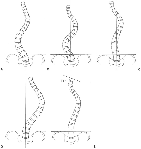 Fig. 3-4 King classification of curve patterns. A: Type I—“S” shaped pattern with both the thoracic and lumbar curves crossing the midline. The lumbar curve is larger and less flexible. B: Type II—“S” shaped curve with more severe and less flexible thoracic component. C: Type III—lumbar curve does not cross the midline and is centered over the sacrum. D: Type IV—long thoracic curve with L4 directed to the thoracic curve. E: Type V—double thoracic curve with T1 directed to the concavity of the upper curve. The upper curve is the structural curve. |
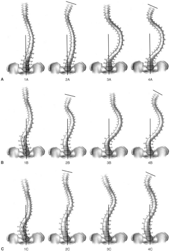 Fig. 3-5 Lumbar modifiers. A: Type A—minimal lumbar curve: 1A—major thoracic curve, 2A—double thoracic, 3A—double major curves, 4A—triple major. B: Type B—moderate lumbar curve: 1B—major thoracic curve, 2B—double thoracic curve, 3B—double major curves, 4B—triple major. C: Type C—large lumbar curve: 1C—major thoracic curve, 2C—double thoracic, 3C—double major curves, 4C—triple major curves. |
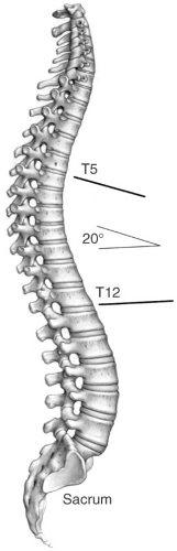 Fig. 3-6 Sagittal thoracic modifiers. Measurements from T5 to T12. Minus curve <10 degrees, neutral curve 10 to 40 degrees, positive curve >40 degrees. In this example the curve is 20 degrees therefore falls in the neutral curve range. |
Suggested Reading
Dangerfield PH. The classification of spinal deformities. Pediatr Rehabil. 2003;6:133–136.
King HA, Moe JH, Bradford DS, et al. The selection and fusion levels in thoracic idiopathic scoliosis. J Bone Joint Surg. 1983;65A:1302–1313.
Lenke LG, Betz RR, Harms J, et al. Adolescent idiopathic scoliosis: A new classification to determine the extent of spinal arthrodesis. J Bone Joint Surg. 2001;83A:1169–1181.
Poncet P, Dansereau J, Labelle H. Geometric torsion in idiopathic scoliosis: Three-dimensional analysis and proposal for a new classification. Spine. 2001;26:2235–2243.
Imaging of Scoliosis
Imaging of scoliosis begins with quality full-length standing radiographs of the entire spine. Radiographs are essential for curve measurement, classification, and treatment planning. Detection of congenital anomalies can also be accomplished radiographically. The number and type of views may vary with the patient’s age, clinical status, and type of curve detected clinically. Orthopaedic surgeons rely on the standing anteroposterior (PA), lateral, and lateral bending views. The latter allow assessment of curves to determine if they are fixed (structural) in which case they do not change, or nonstructural in which case they correct when bending to the convex side.
Posteroanterior (PA) radiograph: Should include the occiput to the sacrum (see Fig. 3-7)
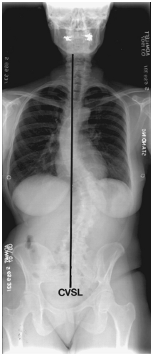
Fig. 3-7 Standing posteroanterior (PA) radiograph with thoracic and lumbar curves. The central vertical sacral line (CVSL) extends vertically through the mid-sacrum. Both curves cross the midline with the lumbar curve being more exaggerated.
Use central vertical sacral line to evaluate curves
Cobb method to measure curves (Fig. 3-1)
Pedicle or spinous process method to measure rotation (Fig. 3-2)
Lateral bending radiographs: Same field of view as PA radiographs
Measure changes in curves using same end vertebrae
With multiple curves, the degree of correction is important
If lumbar correction exceeds thoracic, only the thoracic is fused
When lumbar correction is less than thoracic both are fused
Lateral radiograph: Should include occiput to hips (see Fig. 3-8)
Evaluate lumbar lordosis using L1-5
Evaluate thoracic kyphosis T4-12
T9 offset using vertical line from the hip
Sacral slope
Pelvic tilt
Vertebral height T9-S1
Disc space height and symmetry
Special studies: In certain cases computed tomography (CT) or magnetic resonance imaging (MRI)
may be required to fully evaluate the curves, spinal canal, or associated congenital anomalies. Thin-section CT with reformatting in the sagittal, coronal, and oblique planes or three-dimensional reconstructions may be required. On occasion, discograms and facet injections may be required to confirm symptomatic levels.
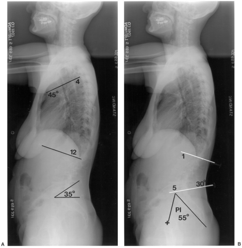 Fig. 3-8 Standing lateral radiograph of the spine. A: Sacral slope is the angle formed by a horizontal line and the end plate of S1 (range 17 to 63 degrees, mean 42 degrees); in this case it is 35 degrees. Thoracic kyphosis measured from the endplates of T12 and T4 (mean 41 degrees, range 0 to 69 degrees); in this case 45 degrees. B: Lumbar lordosis measured from the endplates of L1 and L5 (14 to 69 degrees, mean 43 degrees); in this case 30 degrees. The pelvic incidence (PI) is a key parameter for spinal balance and is measured by a line perpendicular to the center of the sacral end plate and a second line from the central femoral axis (+) to the center of the sacral end plate (range 33 to 82 degrees, mean 55 degrees) in this case 55 degrees. |
Suggested Reading
Berquist TH. Imaging of the postoperative spine. Radiol Clin North Am. 2006;44:407–418.
Lenke LG, Betz RR, Harms J, et al. Adolescent idiopathic scoliosis: A new classification to determine the extent of spinal arthrodesis. J Bone Joint Surg. 2001;83A:1169–1181.
Oestreich AE, Young LW, Poussaint TY. Scoliosis circa 2000: Radiologic imaging perspective. I. Diagnosis and pretreatment evaluation. Skeletal Radiol. 1998;27:591–605.
Vialle R, Levassor N, Rillardon L, et al. Radiographic analysis of the sagittal alignment and balance of the spine in asymptomatic subjects. J Bone Joint Surg. 2005;87A:260–267.
Treatment of Scoliosis
Management of scoliosis may be complex requiring multiple or combined approaches depending on the degree of involvement and the likelihood of curve progression. Treatment options include simple observation and follow-up, bracing, and surgical intervention with spinal arthrodesis. The most important initial decision is whether or not the curve will progress if not treated. The risk of progression is increased with larger curves and in females. In children and adolescents, curves up to 30 degrees tend not to progress. Curves of 30 to 39 degrees in a child are a good indication for bracing as 68% progress. Curves >45 to 50 degrees usually progress and are an indication for surgical arthrodesis. A brace treated curve that progresses 45 to 50 degrees is also an indication for surgical intervention. In adults, there is often associated degenerative disease and concern regarding cosmetic appearance and pain. For purposes of this text the focus will be on options for operative instrumentation. Instrumentation may include short or long segments and anterior, posterior, or combined approaches.
Anterior Instrumentation
Usually used for short-segment scoliosis or in combination with other systems. Examples include the following:
Dwyer instrumentation (see Fig. 3-9)
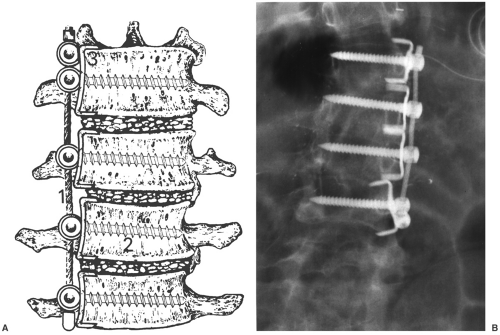 Fig. 3-9 Dwyer instrumentation. A: Illustration of Dwyer fixation with flexible cable (1), cancellous screw with central hole in the head for cable (2), vertebral staple (3). (Courtesy of Zimmer, Warsaw, Indiana.) B: Anteroposterior (AP) radiograph on a patient with Dwyer instrumentation. |
Indications
Lumbar and thoracic idiopathic scoliosis
Neurogenic scoliosis
Lordotic spinal deformities
Instrumentation: Flexible titanium cable; cancellous screws cannulated for the cable and staples
Advantages: Excellent correction of primary curve
Disadvantages: Cable rupture; kyphotic affect; not effective for multiple curves
Zielke instrumentation
Indications: Idiopathic and degenerative lumbar or thoracic scoliosis
Instrumentation: Similar to Dwyer except that cable replaced with stainless steel rod
Advantages: Improved derotation capability; avoids excess kyphosis
Disadvantages: More difficult procedure; solid fusion more difficult to obtain with larger curves
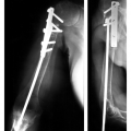
Texas Scottish Rite Hospital Instrumentation (see Fig. 3-10)
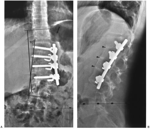 Fig. 3-10 Texas Scottish Rite Hospital (TSRH) instrumentation. Anteroposterior (AP) (A) and lateral (B) radiographs after anterior TSRH instrumentation. Note the rod replaces the cable used in the Dwyer system. The twelfth rib (arrow in A) has been resected and used for interbody fusion (arrowheads). |
Similar to the description in the preceding text; uses a single rod, screws, staples, and washers
Posterior Instrumentation
Usually used for longer segment scoliosis procedures; multiple systems available
Harrington instrumentation (see Fig. 3-11)
Indications: Longer segment thoracic and lumbar scoliosis
Instrumentation: Two rod systems, one for distraction and one for compression; distraction has collar on one end and ratches on the other; compression rod is threaded; hooks are attached to create compression or distraction
Moe instrumentation
Indications: Long-segment thoracic or lumbar scoliosis
Instrumentation: Similar to Harrington except that the rod is square distal to the collar and hooks have square holes to reduce rotation
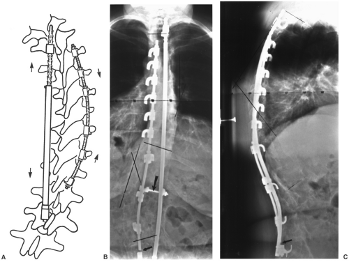 Fig. 3-11 Harrington instrumentation. A: Illustration of Harrington instrumentation with a threaded compression rod on the right (arrows) and a distraction rod on the left (arrows) with ratchets superiorly. Anteroposterior (AP) (B) and lateral (C) radiographs with compression rod on the right and distraction rod on the left. There is a cross-link for stability (arrow) and a fracture in the distal compression rod (small black arrow). |
Luque Instrumentation (see Fig. 3-12)
Indications: Scoliosis and congenital deformities
Instrumentation: Smooth straight or “L” shaped rods with sublaminar wires instead of hooks
Advantages: Corrective forces applied at each vertebral level
Disadvantages: Sublaminar wires may cause neurologic damage
Wisconsin Instrumentation
Similar to Luque instrumentation except that wires pass through the base of the spinous process with paired buttons to protect the bone
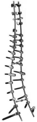
Corel-Dubousset Instrumentation (see Fig. 3-13)
Indications: Long-segment scoliosis
Instrumentation: Diamond knurled coated rods to improve hook fixation; hooks similar to Harrington system but have set screws to improve fixation to rod and designed for lamina, pedicle, or transverse process placement; transverse crosslinks for three-dimensional stability
Advantages: Improved frontal plane correction and kyphosis; maintains lumbar lordosis; postoperative bracing not needed
Disadvantages: Rigid fixation may stress the spine to be shielded; increased instrumentation decreases space for bone graft
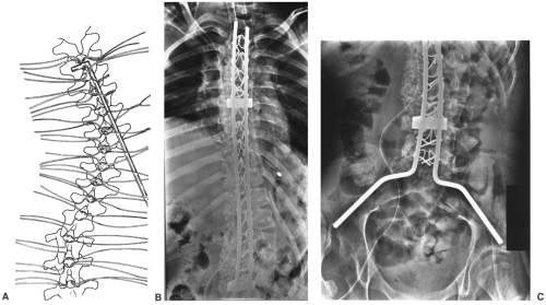 Fig. 3-12 Luque instrumentation. A: Illustration of sublaminar wires and rod placement. The rod is smooth with no ratchets or hooks. Anteroposterior (AP) radiographs (B and C) after Luque rod and sublaminar wire placement for scoliosis. Note the extensive bone grafting on the right. |
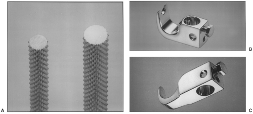 Fig. 3-13 Cotrel-Dubousset instrumentation. Diamond-pointed rod surface (A), various hook configurations with set screws to secure the hook to the rod (B and C), sacral screws (D) and crosslinks (E), and system attached to bone model (F). (Courtesy of Stuart Specialty, Spine Division, Greensburg, Pennsylvania.) Anteroposterior (AP) (G) and lateral (H) radiographs after Cotrel-Duboussett instrumentation with transverse stabilizers proximally and distally. |
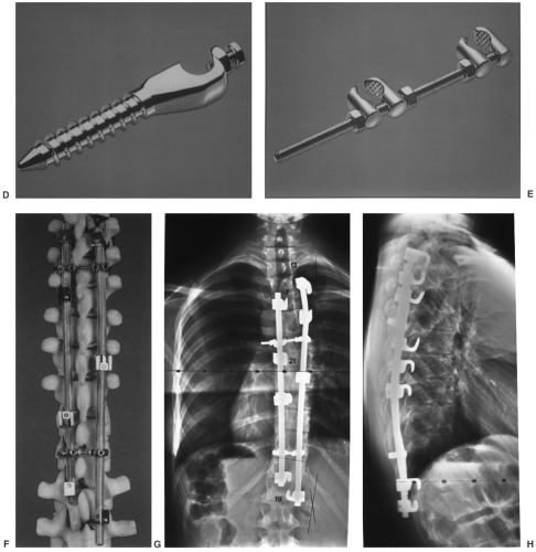 Fig. 3-13 (Continued). |
Texas Scottish Rite Hospital Instrumentation
Indications: Long- or short-segment scoliosis; may be used anteriorly or posteriorly
Instrumentation: Rods smooth with hexagonal ends, hooks, eye bolt connectors for crosslinks, cancellous screws
ISOLA Instrumentation (see Fig. 3-14)
Designed to simplify the number of implants and improve sacral fixation
Instrumentation: Multiple rod configurations, hooks, cancellous screws, rod connectors, crosslinks, spacers, and washers
Advantages: Three-dimensional stability and minimal postoperative support required
Minimally Invasive Spine Instrumentation System: Similar to the description in the preceding text with ability to use rods, hooks, and pedicle screws. Instruments inserted through small incisions with screws placed percutaneously over guide wires (see Fig. 3-15)
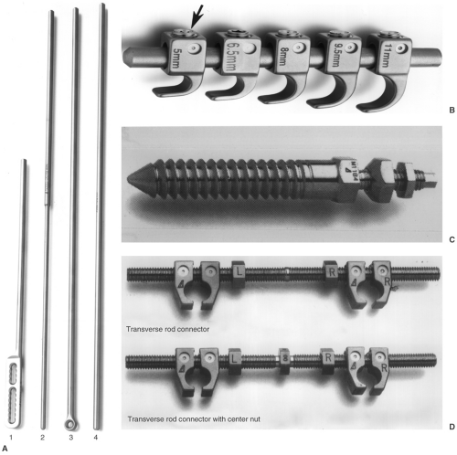 Fig. 3-14 ISOLA instrumentation. A: Rods: (1) plate rod, (2) dual diameter rod, (3) eye rod, (4) smooth rod. B: Hooks with end tightening screw (arrow). C: Cancellous sacral screw. D: Transverse connector rods. (Courtesy of Acromed, Cleveland, Ohio.) Posteroanterior (PA) (E) and lateral (F) radiographs after ISOLA instrumentation for scoliosis. |
 Fig. 3-14 (Continued). |
 |
Suggested Reading
Asher M, Lai SM, Burton D, et al. Safety and efficacy of ISOLA instrumentation and arthrodesis for adolescent idiopathic scoliosis: Two-12-year follow-up. Spine. 2004;29:2013–2023.
Berquist TH. Imaging of the postoperative spine. Radiol Clin North Am. 2006;44:407–418.
Kim YJ, Lenke LG, Cho SK, et al. Comparative analysis of pedicle screw versus hook instrumentation in posterior spinal fusion of adolescent idiopathic scoliosis. Spine. 2004;29:2040–2048.
Lonstein JE. Scoliosis: Surgical versus nonsurgical treatment. Clin Orthop. 2006;443:248–259.
Remes V, Helenius I, Schlenzka D, et al. Cotrel-Dubousset (CD) or Universal Spine System (USS) instrumentation in adolescent idiopathic scoliosis (AIS): Comparison of midterm clinical, functional and radiologic outcomes. Spine. 2004;29:2024–2030.
Imaging of Postoperative Complications
Complications associated with scoliosis instrumentation vary with the type of procedure and patient status. Complications may be directly related to the procedure and occur intraoperatively, perioperatively, or later in the course of follow-up. Complications may also be related to other organ systems. Certain complications may be increased if postoperative immobilization or casting is required. Fortunately, new techniques have reduced the need for long-term postoperative support.
Intraoperative complications include the following:
Laminar fracture
Nerve injury (sublaminar wires, pedicle screws)
Improper screw placement
Sensory loss at hook sites
Dural tears
Immediate postoperative complications include the following:
Pneumonia and pleural effusion or hemothorax
Pneumothorax
Gastrointestinal-adynamic ileus, duodenal ulcer, superior mesenteric artery syndrome (midline compression due to supporting devices such as body casts)
Deep infection
Deep venous thrombosis
Reoperation due to suboptimal instrument placement
Delayed complications include the following:
Loss of correction
Instrument failure
Rod fracture (see Figs. 3-16, 3-11B and C)
Hook displacement (Fig. 3-16)
Screw pullout
Cable rupture
Deep infection
Pseudarthrosis
Chronic pain
Neurologic
Imaging of complications requires appropriate selection of techniques. Serial radiographs are most useful to evaluate correction of curves and changes in deformity. Evaluation of bone graft may require CT, radionuclide scans, or MRI.
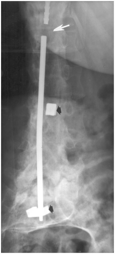 Fig. 3-16 Anteroposterior (AP) radiograph demonstrating fracture of the Harrington rod (arrow) and displaced hooks (black arrows). |
Typically graft fusion requires 6 to 9 months. Pseudarthrosis is the most feared complication and is reported in 5% to 32% of patients depending on the extent of the procedure. Deep infection is reported in 1% to 3% of cases. Table 3-2 summarizes complications and imaging approaches.
Table 3-2 SCOLIOSIS INSTRUMENTATION COMPLICATIONS | ||||||||||||||||||||||||||||||||
|---|---|---|---|---|---|---|---|---|---|---|---|---|---|---|---|---|---|---|---|---|---|---|---|---|---|---|---|---|---|---|---|---|
| ||||||||||||||||||||||||||||||||
Suggested Reading
Ali RM, Boachie-Adjei O, Rawlins BA. Functional and radiographic outcomes after surgery for adult scoliosis using third generation instrumentation techniques. Spine. 2003;28:1163–1169.
Asher M, Lai SM, Burton D, et al. Safety and efficacy of Isola instrumentation and arthrodesis for adolescent idiopathic scoliosis: Two to 12 year follow-up. Spine. 2004;29:1013–2023.
Hedequist DJ, Hall JE, Emans JB. The safety and efficacy of spinal instrumentation in children with congenital spine deformities. Spine. 2004;29:2081–2086.
Kim YJ, Lenke LG, Samuel K, et al. Comparative analysis of pedicle screw versus hook instrumentation in posterior spinal fusion of adolescent idiopathic scoliosis. Spine. 2004;29:2040–2048.
Oestreich AE, Young LW, Poussaint TY. Scoliosis circa 2000: Radiologic imaging perspective. II. Treatment and follow-up. Skeletal Radiol. 1998;27:651–656.
Remes V, Helenius I, Schlenzka D, et al. Cotrel-Dubousset (CD) or Universal Spine System (USS) instrumentation in adolescent idiopathic scoliosis (AIS): Comparison of midterm clinical, functional and radiologic outcomes. Spine. 2004;29:2024–2030.
Spondylolisthesis and Degenerative Disease
Surgical techniques for treatment of cervical and lumbar degenerative changes have changed dramatically over the last decades. Clinical features, treatment options, and the role of pre- and postoperative imaging and complications will be reviewed in this section.
Lumbar Spondylolisthesis and Degenerative Disease
Spondylolisthesis may occur at any level. Subluxation at L5-S1 is commonly associated with an L5 pars defect (spondylolisis). Spondylolisis is bilateral in 74% of patients and occurs in 5% to 7.2% of the general population. Degenerative spondylolisthesis occurs most commonly (80%) at L4-5. Multiple levels are involved in more than 5% of patients. The etiology of spondylolisthesis has been debated for years. Most feel that both acquired and congenital causes are implicated. A recent classification is summarized in Table 3-3.
Table 3-3 MARCHETTI-BARTOLOZZI CLASSIFICATION OF SPONDYLOLISTHESIS | ||||||||||
|---|---|---|---|---|---|---|---|---|---|---|
|
The high dysphasic type refers to disorders at L5-S1, which usually become symptomatic during adolescence. There is frequently a dome-shaped articular surface or vertical sacral angle. Low dysplastic spondylolisthesis is frequently associated with spinal bifida occulta and becomes symptomatic in the young adult years. Subluxation in the low dysplastic form occurs without kyphotic angulation at L5-S1.
Degenerative disease may be associated with spondylolisthesis. The spine can be anatomically divided into two or three columns. For purposes of degenerative disease two columns may be preferred. The anterior column consists of the vertebral body, intervertebral discs, and longitudinal ligaments. The posterior column consists of the posterior bony structures, including the transverse processes and the attaching ligaments and muscles. Degenerative disease may affect one or both columns and typically involves multiple levels. This section will focus on the lumbar and cervical degenerative disease and surgical treatment approaches.
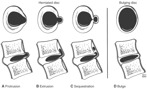 Fig. 3-17 Disc bulge, protrusion, extrusion, and sequestration based on consensus terminology. (From Witte RJ, Lane JI, Miller GM, et al. Spine. In: Berquist TH, ed. MRI of the musculoskeletal system, 5th ed. Philadelphia: Lippincott Williams & Wilkins; 2006:121–202.) |
Common Terminology
Ankylosis: Nonsurgical joint fusion seen with several arthropathies including ankylosing spondylitis
Arthrodesis: Surgical immobilization of a joint or disc space
Disc disorders (see Fig. 3-17)
Disc bulge—broad-based expansion of the circumference of the disc due to loss of interspace height with extension beyond the confines of the adjacent vertebral body secondary to laxity of the annular fibers without evidence of concentric tear (see Figs. 3-17D and 3-18).
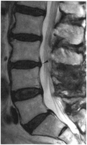
Fig. 3-18 Disc bulges. Sagittal magnetic resonance (MR) image demonstrating a disc bulge at L3-4 (arrowhead).
Disc protrusion—focal broad-based expansion of disc material that is confined by the outer annular layers. On axial and sagittal MR images it is seen only at the disc level (see Figs. 3-17A and 3-19).
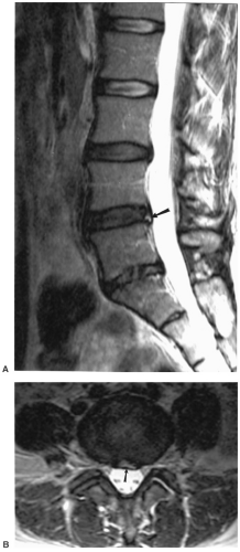
Fig. 3-19 Disc protrusion. Sagittal (A) and axial (B) magnetic resonance (MR) images demonstrating a disc protrusion at L4-5. On the sagittal T2-weighted image (A) there is increased signal intensity in the posterior annulus (arrow) compatible with an annular tear. The axial image (B) demonstrates a focal defect (arrow) with flattening of the ventral thecal sac.
Disc extrusion—herniation of nucleus pulposus through all layers of the annulus. A small extrusion is difficult to differentiate from a disc protrusion. The disc extrusion appears as a focal soft tissue mass that may displace the thecal sac or adjacent nerve roots (see Figs. 3-17B and 3-20).
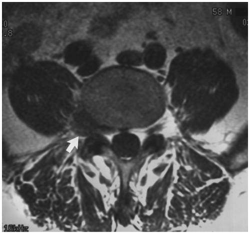
Fig. 3-20 Disc extrusion. Axial magnetic resonance (MR) image demonstrating a lateral fragment (arrow) displacing the L4 nerve root.
Disc sequestration—disc material that has herniated through all layers of the annulus and is no longer connected to the parent disc. The sequestered fragment may migrate several disc levels superiorly or inferiorly (see Figs. 3-17C and 3-21).
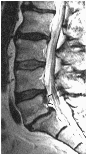
Fig. 3-21 Disc sequestration. Sagittal magnetic resonance (MR) image demonstrating a posterior disc fragment posterior to the L5 vertebral body (arrows) and displaced from the parent disc.
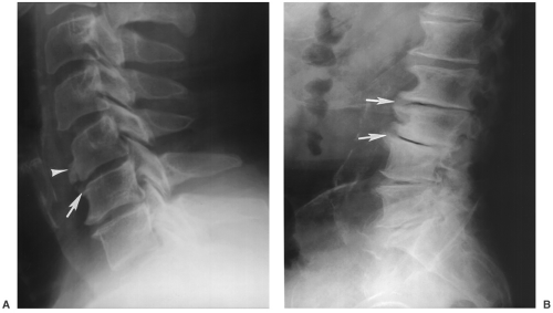
Fig. 3-22 Osteophytes. Lateral radiographs of the cervical (A) and lumbar spine (B) demonstrating marginal (arrows in A and B) and nonmarginal (arrowhead in A) osteophytes. There is also vacuum disc phenomenon and advance degenerative change in the lumbar spine (B).
Osteophytes: Pathologic bony outgrowth
Marginal osteophyte—horizontal bony projection from the vertebral end plate seen in degenerative spine disease (see Fig. 3-22)
Nonmarginal osteophyte—bone projection several millimeters away from the vertebral end plate (Fig. 3-22A)
Paraspinal osteophyte—paraspinal ossification in the soft tissues surrounding the vertebra seen in diffuse idiopathic skeletal hyperostosis (DISH) (see Fig. 3-23)
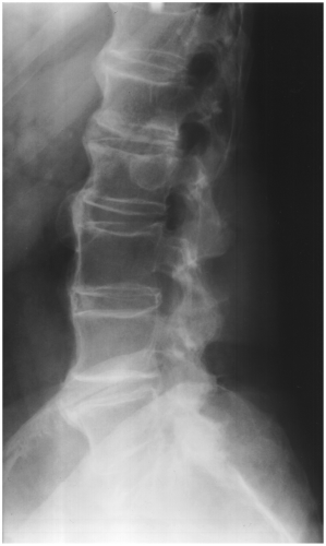
Fig. 3-23 Diffuse idiopathic skeletal hyperostosis (DISH). Lateral radiograph of the lumbar spine demonstrating ossification of the paraspinal soft tissues with normal disc spaces.
Retrolisthesis: Posterior displacement or subluxation of a vertebral body on the inferior adjacent vertebra (see Fig. 3-24)
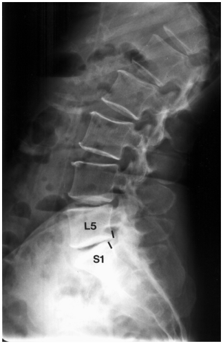
Fig. 3-24 Lateral radiograph of the lumbar spine demonstrating posterior displacement of L5 on S1 (lines).
Spondylolisthesis: Anterior displacement of a vertebral body on the adjacent body below (see Fig. 3-25)
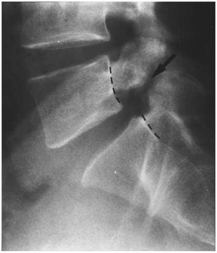
Fig. 3-25 Spondylolisthesis. Lateral radiograph of the spine demonstrating anterior displacement of L5 on S1 (broken lines) due to pars defect (arrow) at L5.
Spondylolisis: Used to describe disruption of the pars (Fig. 3-25)
Spondylosis: Used to describe any of a variety of degenerative changes in the spine
Syndesmophyte: Vertically oriented ossification bridging the vertebral bodies seen with ankylosing spondylitis and other spondyloarthropathies (see Fig. 3-26)
Fig. 3-26 Syndesmophyte. Anteroposterior (AP) radiograph of the lower lumbar spine and sacroiliac joints (A) demonstrating ankylosis of the sacroiliac joints and smooth vertical syndesmophytes along the vertebral margins. Lateral radiograph of the cervical spine (B) demonstrating uniform smooth ossification of the anterior longitudinal ligament.
Suggested Reading
Hammerberg KW. New concepts in pathogenesis and classification of spondylolisthesis. Spine. 2005;30(S6):S4–S11.
Milette P. The proper terminology for reporting lumbar intervertebral disk disorders. AJNR Am J Neuroradiol. 1997;18:1859–1866.
Witte RJ, Lane JI, Miller GM, et al. Spine. In: Berquist TH, ed. MRI of the musculoskeletal system, 5th ed. Philadelphia: Lippincott Williams & Wilkins; 2006:121–202.
Preoperative Imaging
Radiographic imaging of the spine provides valuable information on stability and levels of involvement. In addition to radiographs, CT, MRI, or diagnostic injections in the facets or discs may be required for operative planning
Lumbar radiographs: AP, lateral, coned down lateral lower lumbar spine, obliques, flexion-extension and lateral bending views
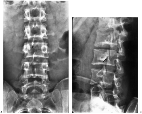
Fig. 3-27 Pedicle sclerosis. Anteroposterior (AP) radiograph of the lumbar spine demonstrates a sclerotic pedicle at L3 on the right (arrow) due to a pars defect on the left demonstrated on the oblique view (arrow in B).
AP view—sclerotic pedicle may be seen with contralateral pars defect (see Fig. 3-27)
Angled AP view (30 degrees to the head) may assist in defining pars defects
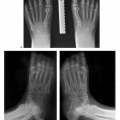
Lateral view—classify spondylolisthesis (Meyerding) (see Fig. 3-28)
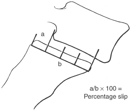
Fig. 3-28 Meyerding classifiction for spondylolisthesis. The vertebral end plate is divided into four equal segments and graded I to IV depending on the degree of slip. Illustration of the Meyerding system at L5-S1. In this case the degree of slip is 25% or grade I.
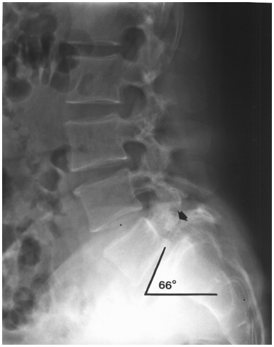
Fig. 3-29 Sacral angle (slope). Lateral radiograph measuring the sacral angle by drawing a line along the upper end plate of S1 and the horizontal (range 17 to 63 degrees, mean 42 degrees). In this case the sacral angle is 66 degrees. Note the pars defect and sclerosis (arrow) and grade I anterior subluxation of L5 on S1.
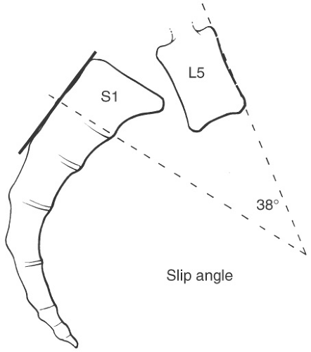
Fig. 3-30 Slip angle. The slip angle is measured by a line along the upper endplate of L5 and the second line perpendicular to the posterior aspect of the sacrum. A high slip angle indicates greater risk for instability, progression of slip, and reduced healing potential.
Oblique views—facet arthrosis and pars defects (see Fig. 3-31)
Motion studies—evaluate stability, disc space, and curve changes (see Fig. 3-32)
CT: Clarify pars defects (see Fig. 3-33), spinal stenosis
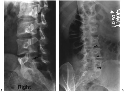
Fig. 3-31 Oblique views. A: Right oblique radiograph demonstrating a pars defect at L5 (arrow). B: Oblique radiograph demonstrating advanced facet arthropathy with sclerosis, joint space narrowing, and marginal osteophytes (arrowheads) at multiple levels.
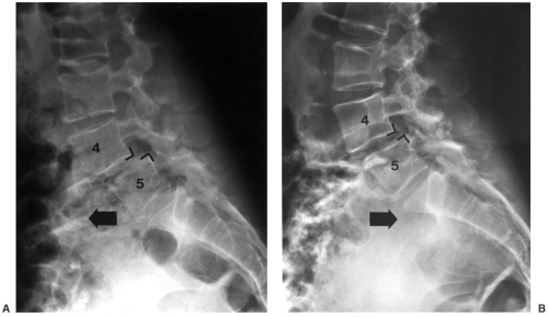
Fig. 3-32 Motion studies. Flexion (A) and extension (B) radiographs in a patient with grade I degenerative subluxation of L4 on L5 that increases with flexion.Related posts:

Stay updated, free articles. Join our Telegram channel

Full access? Get Clinical Tree

 Get Clinical Tree app for offline access