Stereotactic Radiotherapy and Radiosurgery
21.1. INTRODUCTION
Stereotactic radiosurgery (SRS) is a single-fraction radiation therapy procedure for treating intracranial lesions using a combination of a stereotactic apparatus and narrow multiple beams delivered through noncoplanar isocentric arcs. The same procedure when used for delivering multiple dose fractions is called stereotactic radiotherapy (SRT). Both techniques involve three-dimensional imaging to localize the lesion and delivering treatment that concentrates the dose in the target volume and spares as much as possible the normal brain. A high degree of dose conformity is a hallmark of SRS, which is generally achieved by using appropriate circular beams to fit the lesion, optimizing arc angles and weights, and using multiple isocenters or dynamically shaping the field during arc rotations with mini (or micro) multileaf collimators (MLCs).
Accuracy of beam delivery is another hallmark of SRS. It is strictly controlled by a specially designed stereotactic apparatus, which is used through all steps of the process: imaging, target localization, head immobilization, and treatment setup. Because of the critical nature of brain tissue, elaborate quality assurance (QA) procedures are observed. The best achievable mechanical accuracy in terms of isocenter displacement from the defined center of target image is 0.2 mm ± 0.1 mm, although a maximum error of ±1.0 mm is commonly accepted in view of the unavoidable uncertainties in target localization.
The term radiosurgery was coined by a neurosurgeon Lars Leksell in 1951 (1). He developed the procedure in the late 1940s to destroy dysfunctional loci in the brain using orthovoltage x-rays and particle accelerators. His later work involved the use of a specially designed cobalt unit, called the gamma knife (or γ-knife). Currently there are three types of radiation used in SRS and SRT: heavily charged particles, cobalt-60 γ rays, and megavoltage x-rays. Of these, the most commonly used modality is the x-rays produced by a linear accelerator. In analogy to the γ-knife, the linac-based SRS unit may be called the x-ray knife. The γ-knife has better mechanical accuracy, although there is no significant clinical difference between the γ-knife and x-ray knife. The γ-knife also costs more than the x-ray knife; however, both are substantially cheaper than a heavy particle accelerator. Of course, most of the radiation generators used for SRS are also used for other radiotherapy procedures with the exception of the γ-knife, which is dedicated solely for intracranial SRS or SRT.
21.2. STEREOTACTIC RADIOSURGERY TECHNIQUES
Two SRS techniques are described in this chapter: the linac-based x-ray knife and the γ-knife. Greater details are provided on the most frequently used system, the x-ray knife, while a brief review is given on the γ-knife for general information.
A. X-RAY KNIFE
The linac-based SRS technique consists of using multiple noncoplanar arcs of circular (or dynamically shaped) beams converging on to the machine isocenter, which is stereotactically placed at the center of imaged target volume. A spherical dose distribution obtained in this case can be shaped to fit the lesion more closely by manipulating several parameters: selectively blocking parts of the circular field, shaping the beam’s-eye aperture dynamically with a MLC, changing arc angles and weights, using more than one isocenter, and combining stationary beams with
arcing beams. Optimization of some of these parameters is carried out automatically by the treatment-planning software.
arcing beams. Optimization of some of these parameters is carried out automatically by the treatment-planning software.
A.1. Stereotactic Frame
There are basically two linac-based SRS systems: pedestal-mounted frame and couch-mounted frame. The frame in this case refers to an apparatus called the stereotactic frame, which is attachable to the patient’s skull as well as to the couch or pedestal. This provides a rigidly fixed frame of coordinates for relating the center of imaged target to isocenter of treatment. Several frames have been developed for general stereotactic applications and some of these have been adopted for SRS. The most noteworthy of the SRS frames are Leksell, Riechert-Mundinger, Todd-Wells, and Brown-Robert-Wells (BRW). These have been described in detail by Galloway and Maciunas (2). Only the BRW frame will be discussed in this chapter.
Figure 21.1 shows the basic stereotactic system with the BRW frame, computed tomography (CT) localizer, angiographic localizer, and a device for fixing the frame to the patient support table. The BRW frame has three orthogonal axes: anterior, lateral, and axial (Fig. 21.2). The three axes intersect at the center of the circular frame and the origin is defined 80 mm from the top surface of the ring.
The CT localizer frame is equipped with nine fiducial rods, which appear as dots in the transaxial slice image. Since the location of these points in the frame space is precisely known, any point in the image can be defined in terms of the frame coordinates. A patient docking device couples the frame to the accelerator through the patient support system (pedestal or couch-mount bracket). The origin of the frame is aligned with the linac isocenter to within 0.2 to 1.0 mm, depending on the system (pedestal-mounted systems tend to be more accurate than the couch-mounted ones). The angiographic localizer frame consists of four plates and attaches to the BRW head ring. Each plate is embedded with four lead markers, which act as fiducial markers for the angiographic images.
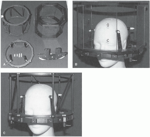 Figure 21.1. Basic stereotactic system showing A: (starting clockwise from upper right) computed tomography (CT) localizer, angiographic localizer, patient-positioning mount, and head ring with posts and pins; B: angiographic localizer; and C: CT localizer. (From Bova FJ, Meeks SL, Friedman WA. Linac radiosurgery: system requirements, procedures, and testing. In: Khan FM, Potish RA, eds. Treatment Planning in Radiation Oncology. Baltimore, MD: Williams & Wilkins; 1998:215-241, with permission.) |
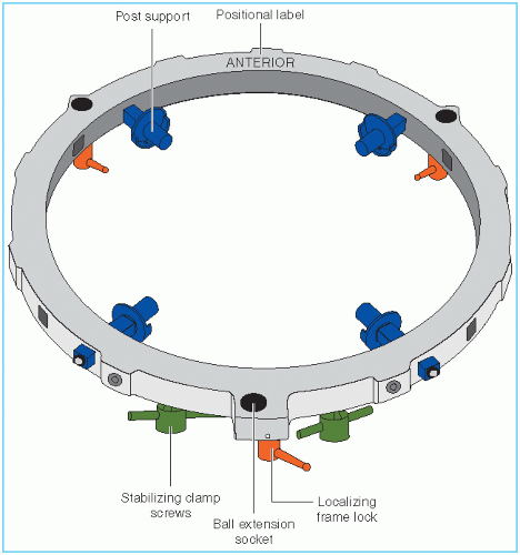 Figure 21.2. Schematic drawing of Brown-Robert-Wells frame. (From Cho KH, Gerbi BJ, Hall WA. Stereotactic radiosurgery and radiotherapy. In: Levitt SH, Khan FM, Potish RA, et al., eds. Technological Basis of Radiation Therapy. Philadelphia, PA: Lippincott Williams & Wilkins; 1999:147-172, with permission.) |
The magnetic resonance imaging (MRI) localizer is a slightly modified version of the CT localizer and is compatible with MRI. It has fiducial rods whose locations are precisely known with respect to the BRW frame, thus allowing the localization of any point within the MRI image.
A special relocatable head ring, called the Gill-Thomas-Cosman (GTC), has been designed for fractionated SRT (Fig. 21.3). It uses a bite block system, headrest bracket, and Velcro straps attached to the BRW frame.
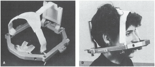 Figure 21.3. A: The Gill-Thomas-Cosman (GTC) relocatable head ring with bite block and Velcro straps. B: The GTC head ring worn by the patient. (From Cho KH, Gerbi BJ, Hall WA. Stereotactic radiosurgery and radiotherapy. In: Levitt SH, Khan FM, Potish RA, et al., eds. Technological Basis of Radiation Therapy. Philadelphia, PA: Lippincott Williams & Wilkins; 1999:147-172, with permission.) |
A.2. Linac Isocentric Accuracy
An essential element of the SRS procedure is the alignment of stereotactic frame coordinates with the linac isocenter (point of intersection of the axes of rotation of the gantry, collimator, and couch). Acceptable specification of linac isocentric accuracy requires that the isocenter (mechanical as well as radiation isocenter) remain within a sphere of radius 1 mm with any combination of gantry, collimator, and couch rotation. The same specification holds good for a linac used for SRS, with an added stipulation that the stereotactically determined target isocenter is coincident with the linac isocenter within ±1 mm (3). Tests required to check the linac specifications and its isocentric accuracy are described in the AAPM Reports 54 and 40 (3,4). These recommendations, which are also discussed in Chapter 17, form the basis of linac QA required for SRS.
A.3. Stereotactic Accuracy
The BRW frame system includes a verification device called the phantom base (Fig. 21.4). It has identical coordinates (anteroposterior, lateral, and vertical) to those of the BRW frame. As a standalone device, it provides an absolute frame of reference for stereotactic coordinates of the entire system: BRW frame, patient support system, and the localizer systems for CT, MRI, and angiography. The accuracy of the phantom base should be carefully maintained because it serves as a reference standard for all other steps in the stereotactic localization process. Gerbi et al. (5) have constructed a simple and mechanically rugged device to routinely test the accuracy of the phantom base.
Lutz et al. (6) have described a procedure of using the phantom base to check the alignment of radiation isocenter with the target point defined by the coordinates set on the BRW pedestal. This test is performed by setting the target point (treatment isocenter) coordinates on the phantom base. The tip of the phantom base pointer is matched to the tip of the transfer pointer. The tapered tip of the transfer pointer is then replaced with a tungsten ball, thus ensuring that its center is located exactly at the tapered tip position (Fig. 21.5A). The transfer pointer [also known as the target simulator) is then attached to the pedestal (also known as the independent support stand (ISS)], whose coordinates are set to the same BRW coordinates as those set on the phantom base. A series of port films of the tungsten ball is taken at a number of gantry- and couch-angle combinations (Fig. 21.5B). Figure 21.5C shows the results for eight gantry-table combinations.
Concentricity of the ball image within the circular field is analyzed with a special magnifying eyepiece containing a fine scale. This test can indicate alignment to within ±0.1 mm.
Concentricity of the ball image within the circular field is analyzed with a special magnifying eyepiece containing a fine scale. This test can indicate alignment to within ±0.1 mm.
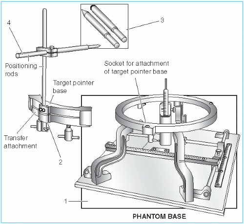 Figure 21.4. Schematic of the phantom base (1), transfer attachment (2), interchangeable pointer and target ball devices (3), and transfer pointer assembly (4). (From Cho KH, Gerbi BJ, Hall WA. Stereotactic radiosurgery and radiotherapy. In: Levitt SH, Khan FM, Potish RA, et al., eds. Technological Basis of Radiation Therapy. Philadelphia, PA: Lippincott Williams & Wilkins; 1999:147-172, with permission.) |
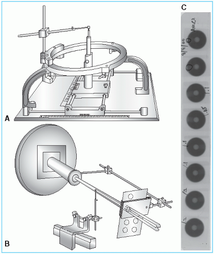 Figure 21.5. A: Schematic of target simulator (steel ball) attached to the Brown-Robert-Wells phantom base. B: Target simulator mounted on the pedestal to verify target alignment with radiation isocenter as a function of table and gantry angles. C: Port films of the tungsten ball for eight gantry-ball combinations. (Figure 21.5A,B is reproduced from Lutz W, Winston KR, Maleki N. A system for stereotactic radiosurgery with a linear accelerator. Int J Radiat Oncol Biol Phys. 1988;14:373, with permission.) |
In the couch-mounted system, the tip of the phantom pointer is aligned with the intersection point of the wall-mounted lasers. After a precise alignment, the tapered tip is replaced with the tungsten ball. The center of this sphere simulates the target point within the patient. Verification films are then taken for a number of gantry- and couch-angle combinations. This test ensures that the target point, the radiation isocenter, and the intersection point of the wall-mounted lasers are aligned regardless of the gantry or table position.
A.4. Overall Accuracy
Related posts:


Stay updated, free articles. Join our Telegram channel

Full access? Get Clinical Tree


