Introduction
The subaxial cervical spine refers to cervical vertebrae located below the “axis” (C2) and is a critical distinction due to inherent biomechanical differences from vertebral levels more cephalad and caudad. Responsible for the majority of cervical range of motion, vertebrae ranging from C3 to C7 contribute roughly 70 of flexion, 40 of extension, 30 of lateral bending, and 45 of rotation to either side. Furthermore, in the native cervical spine, C3–C7 (specifically, the facet joints) is responsible for about two-thirds of the total axial load imposed by the cranium. The remaining load is then distributed among cervical intervertebral discs. These relationships are held in a close equilibrium that is ultimately dependent upon a precise sagittal alignment, where the global cervical lordosis (i.e., C2–C7 curvature), sagittal vertical axis (SVA), T1 slope (T1S), and various other radiographic parameters cohesively interact.
However, in the setting of various pathologies, these biomechanical relationships are frequently disrupted, often resulting in a redistribution of axial loading and diminished capacity to maintain native range of motion. Ultimately, these findings stress the importance of making appropriate radiographic measurements in the cervical spine, as the magnitude of radiographic disturbance is associated with disease prognosis and may help guide surgical management. As such, the present chapter will discuss the importance of critical subaxial radiographic measures, with particular emphasis placed on the clinical relevance and technique required to accurately perform these assessments.
Specific Radiographic Parameters
While indications for specific radiographic measures may differ based upon the presenting situation, certain assessments can be made routinely in a clinical evaluation of the cervical spine. Broadly speaking, these measures assess the overall alignment and sagittal balance of the cervical spine in relation to adjacent vertebrae, intervertebral discs, and neighboring soft tissues. In select situations, such as those seen in traumatic cervical spine injuries, supplementation of these general measures may require assessments of overall stability, as this information may help guide subsequent surgical planning. Moreover, postoperatively, radiographic assessment is particularly important, as this allows adequate visualization of osseous fusion and inspection of instrumentation and may help the practitioner assess for known complications after a cervical procedure. Overall, a collective understanding of the radiographic techniques involved in the evaluation of the cervical spine is an invaluable asset to the spine surgeońs armamentarium and is necessary for proper patient management. All measures are made using standing lateral views of the cervical spine unless otherwise specified.
General Cervical Spine
Contour lines
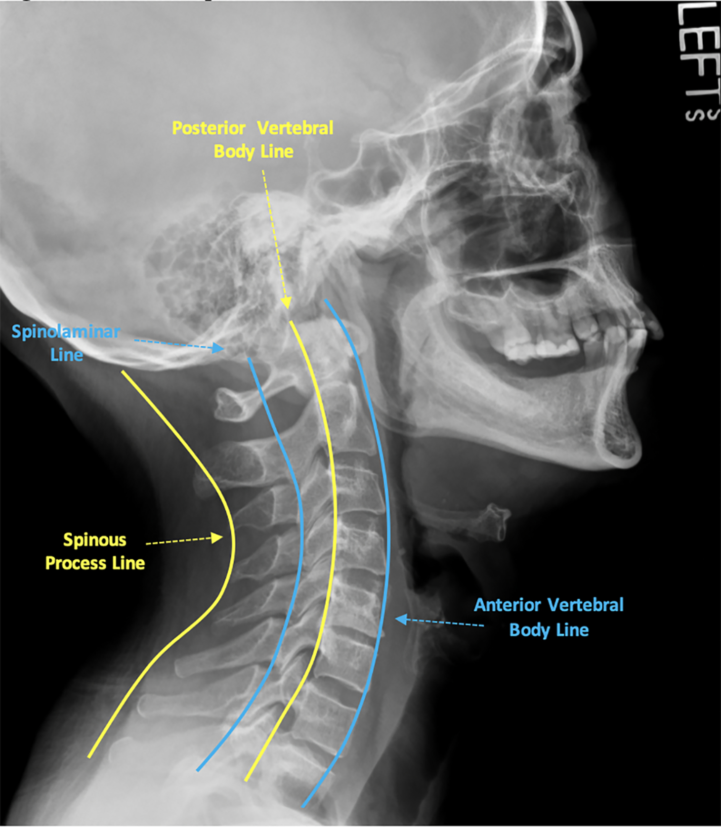
Contour lines for the cervical spine are simple drawings that roughly outline the path of the anterior/posterior vertebral bodies, orientation of the lamina, and the spinous processes. As such, these lines are named the anterior vertebral line, posterior vertebral line, spinolaminar line, and posterior spinal line, respectively. They are frequently used to make quick assessments of overall cervical alignment, where disruption in a given line (defined as ≥ 3 mm translation in adults, ≥ 5 mm in children) raises suspicion of bony or ligamentous injury. To make these measurements ( Fig. 1 ):
- •
Anterior vertebral line
- •
Start at the anterior border of the dens
- •
Draw a line following the anterior edge of each vertebral body from C2 to C7, passing through the corners of the corresponding anterior endplates
- •
- •
Posterior vertebral line
- •
Start at the posterior border of the dens
- •
Draw a line following the posterior edge of each vertebral body from C2 to C7, passing through the corners of the corresponding posterior endplates
- •
This will roughly map the anterior border of the spinal canal
- •
- •
Spinolaminar line
- •
Start at the anterior border of the C2 spinous process base (or the anterior edge of the posterior arch of C1, if visible)
- •
Draw a line following the anterior margin of the base of each spinous process, extending to C7
- •
This will roughly map the posterior border of the spinal canal
- •
- •
Posterior spinal line
- •
Start at the tip of the C2 spinous process
- •
Draw a line caudally, connecting the tips of spinous processes from C2 to C7
- •
Some common pitfalls or issues that arise when interpreting and measuring contour lines include pseudosubluxation and concurrence of diffuse degenerative pathology (e.g., osteophytes). Pseudosubluxation is defined as the physiologic translation of one cervical vertebra relative to another, possibly causing a disruption in contour lines. This is traditionally seen in pediatric patients under the age of 7 at C2–C3 or C3–C4 due to underdeveloped cervical paraspinal muscles. Similarly, degenerative cervical spine pathology may make tracing contours difficult, as there may be structural changes that obstruct natural anatomy. In these situations, care should be taken to pass through the approximate location of the native endplate corners, and avoid incorporation of osteophytes or other degenerative changes that may obscure native structures.
In general, contour lines serve as a relatively simple assessment tool that has the greatest utility in trauma settings. Disruptions or step-offs of contour lines may suggest the presence of a fracture or malalignment of the vertebral column. Specifically, step-offs observed upon inspection of anterior or posterior vertebral lines may suggest spondylolisthesis, while disruptions of the spinolaminar or posterior spinal lines may indicate a spinous process fracture (i.e., “Clay Shoveler’s” fracture). However, as these conditions are often diagnosed without the need for such measures, contour line assessment is perhaps best reserved for occult injuries with supplementation with more advanced imaging modalities. Despite this, some studies have suggested further utility for such measures. In 1999, Seybold et al. noted that the posterior vertebral line may be used to assess the integrity of the odontoid, noting that step-offs ≥ 3 mm should be used as a threshold for subsequent computed tomography (CT) evaluation to rule out occult fractures. More recently, in 2016, Oshima et al. demonstrated that the spinolaminar line at the level of C2–C3 can be used in reference to axis (C1) to screen for C1 spinal stenosis. However, with the increased use of CT and magnetic resonance imaging (MRI) studies, contour lines currently see limited clinical use and are often less sensitive than other radiographic assessments.
C2–C7 lordosis
C2–C7 lordosis measures the overall curvature of the cervical spine and is a critical assessment in determining overall sagittal alignment. At present, there are four reliable metrics used to assess cervical lordosis: (1) Cobb angle, (2) Ishihara’s index, (3) Harrisońs C2–C7 posterior tangent method, and (4) the modified Toyama method. Note that the following methods are often simplified by modern radiographic annotation tools, and specific methods may vary between different software interfaces ( Fig. 2 ).
- •
Cobb angle
- •
Draw a line along the inferior endplate of C2
- •
Draw a perpendicular line intersecting this first line
- •
Draw a line along the inferior endplate of C7
- •
Draw a second perpendicular line intersecting this second line
- •
The angle formed by the intersection of the two perpendicular lines is the Cobb angle measurement for cervical lordosis
- •
By convention, lordotic angles are mathematically negative (−), while kyphotic measures are positive (+)
- •
Normal values: − 20 to − 40 degrees
- •
- •
Ishihara’s index
- •
Draw a straight line connecting the posterior inferior corner of C2 to the posterior inferior corner of C7
- •
Draw a perpendicular line connecting this first line to the posterior inferior corner of C3
- •
Repeat for C4–C6
- •
Take the sum of the length of the lines drawn from C3 to C6 and divide by the length of the line connecting C2 and C7
- •
Lines from C3 to C6 are considered positive (+) if they travel from anterior to posterior in order to intersect the line drawn from C2 to C7, while those traveling from posterior to anterior are negative (−)
- •
- •
Harrisońs posterior tangent
- •
Draw a line tangent to the posterior border of C2
- •
Repeat for C7
- •
The angle formed by the intersection of these two lines generates the C2–C7 lordosis
- •
By convention, lordotic angles are mathematically positive (+), while kyphotic measures are negative (−)
- •
- •
Modified Toyama method
- •
Draw a line from the posterior inferior corner of C2 to the posterior superior corner of C7
- •
Kyphotic curves are identified if the posterior walls of the vertebral bodies from C3 to C6 are posterior to this line
- •
Lordotic curves are present if the posterior walls of C3–C6 lie anterior to this line
- •
Straight curves are present if the posterior walls of C3–C6 lie on this line
- •

Currently, there is significant debate over which technique is the most appropriate for routine clinical use. While each method has demonstrated high intra- and interobserver reliability in various studies, the selection of a given approach is likely best dictated by the treating cliniciańs needs. In many instances, assessment of the precise angle of curvature helps guide surgical management, and as such, Cobb angle measurements or Harrisońs posterior tangent may be more useful. However, in 2017, Donk et al. highlighted some of the shortcomings of these angle measurement techniques, noting in particular that lordotic angles under Harrisońs posterior tangent method may present with grossly kyphotic alignments. Here, they suggest the modified Toyama approach may be a better assessment, though emphasize that this technique is limited due to lack of clear quantification techniques. This suggests that there may be some utility in combining multiple techniques to achieve the most accurate assessment of cervical lordosis.
Irrespective of the technique employed, lordosis measures are currently one of the most clinically significant metrics in the radiographic evaluation of the cervical spine. Both anterior and posterior cervical procedures have that tendency to drastically affect lordosis measures secondary to manipulation of intervertebral disc spaces through the use of various interbody implants and/or utilization of posterior decompression. These techniques may inherently be kyphogenic due to iatrogenic damage of various supporting structures and may lead to postoperative losses in lordosis. Studies have identified many patients treated with an isolated cervical decompression who develop eventual deterioration. Similarly, loss of cervical lordosis, whether iatrogenic or not, has been associated with worse health-related quality of life (HRQOL) scores. Such reports have made radiographic assessments of lordosis integral to cervical spine standard of care and are frequently used to guide sagittal corrections in operative management.
Sagittal vertical axis (SVA)
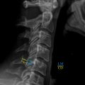
Like cervical lordosis, SVA is another key measure in assessing sagittal alignment of the cervical spine. However, rather than measuring overall curvature, SVA calculates the anterior or posterior translation of C2 relative to the base of the subaxial cervical spine ( Fig. 3 ). The cervical SVA (at times referred to as the “C2–C7 SVA”) is held in contrast to the SVA used for global sagittal alignment, a measure that uses the C7 vertebral body as a reference for larger spinal deformities ( Fig. 3 ).
- •
Sagittal vertical axis
- •
Draw an “X” over the body of C2 by connecting a line from the posterior inferior corner of C2 to the anterior superior border, and a second line from the posterior anterior corner of C2, to the posterior superior border
- •
Draw a vertical axis line through the center of this “X,” perpendicular to the inferior edge of the entire film
- •
Draw an orthogonal line from this axis line connecting the posterior superior corner of C7
- •
Normal values: ≤ 20 mm
- •

Clinically, the connection between SVA and C2–C7 lordosis has only been recently established, with studies suggesting these two measures interact harmoniously in determining sagittal balance. Specifically, with increasing cervical SVA, compensatory suboccipital hyperextension and subaxial cervical flexion are believed to ensue in order to preserve horizontal gaze. Moreover, the evidence surrounding large positive shifts in SVA is arguably greater than that of C2–C7 lordosis, with multiple studies suggesting measures over 40 mm are highly associated with worse disability and HRQOL scores. This understanding has subsequently been implemented in further studies, suggesting that large cervical SVA measures may be more or less amenable to certain approaches. For instance, Kato et al. demonstrated that cervical myelopathy patients with larger C2–C7 SVA measures (≥ 35 mm) had greater incidences of neck pain following decompression than those with smaller SVA values. Realizing this, Miyamoto et al. go on to suggest such patients may be better treated with a concurrent correction of sagittal malalignment through a posterior instrumented fusion. In any case, this illustrates the importance of taking regular SVA measures when making assessments of sagittal balance, and to consider their use in further clinical decision-making.
T1 slope (T1S)
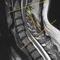
T1S serves as another measurement to assess sagittal balance of the cervical spine and has been associated with other parameters such as C2–C7 lordosis and SVA. While all three measures may not be routinely performed for all patients, in some circumstances, utilization of multiple sagittal assessments may provide the most holistic view of a patient’s cervical alignment and propensity for unfavorable radiographic change. While the T1 slope is thought to be relatively constant, age, posture, and degenerative change may lead to variations over time, ultimately leading to associated changes in sagittal alignment ( Fig. 4 ).
- •
T1 slope
- •
Draw a horizontal axis through the posterior superior corner of the T1 vertebral body
- •
Draw a line tangent to the superior endplate of T1
- •
The acute angle formed by the intersection of these lines represents the T1 slope
- •
Normal values: about 25 ± 5 degrees
- •

Acquisition of the T1 slope measures is dependent upon the obtained field of radiographic exposure. Frequently, radiographs may be positioned more cephalad than intended, leading to poor visualization of the T1 vertebral body. Moreover, variations in patient anatomy such as interference from shoulder contours and neck/truncal obesity may obscure clear boundaries. Though such factors less frequently prevent measurability of C2–C7 lordosis or SVA, clinicians aiming to collect the T1 slope should be aware of these common pitfalls.
However, much like SVA, the T1 slope is a third measurement that closely relates to other radiographic sagittal parameters. In a retrospective review of radiographic images, Park et al. demonstrated that as C2–C7 lordosis increases, the T1 slope also increases. They suggest that the T1 slope may indicate the maximal lordotic curvature a patient may obtain from surgical correction. In addition, some evidence suggests that the magnitude of the T1 slope may be a risk factor for the development of various cervical spine pathologies. Jun et al. noted that high T1 slope was significantly associated with the development of degenerative cervical spondylolisthesis when measured on CT images. Having a low T1 slope, however, has also been associated with increased risks of degenerative cervical spondylotic myelopathy. Collectively, these findings emphasize the clinical value of the T1 slope, though the full utility of this measure continues to evolve.
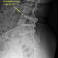
Disc height
Measurements of intervertebral disc height on radiographs face numerous logistical challenges, as degree of radiographic magnification and slight adjustments in patient positioning may prevent an accurate assessment. As such, there have been numerous attempts at techniques for accurate measures of disc height, though each is known to have distinct limitations ( Fig. 5 ).
- •
Endplate-to-endplate disc height
- •
Draw a line from the edge of one vertebral endplate to the adjacent endplate, spanning the intervertebral disc space
- •
The size of this line is the endplate-to-endplate disc height
- •
- •
Distortion-compensated Roentgen analysis (DCRA)
- •
Mark the four corners of two adjacent vertebral bodies
- •
Identify a plane bisecting each vertebral body between the marked points
- •
Identify a third plane lying equidistant from the first two planes bisecting the intervertebral disc space
- •
Draw a perpendicular line from a marked point on the cephalad vertebral body to the third plane
- •
Repeat for the caudal vertebral body
- •
The sum of the distances of these perpendicular lines is the disc height with reference to the marked points
- •
Note: Measured distances from anterior points measure the anterior disc height, and measured distances from posterior points measure the posterior disc height. Points may be placed in the middle of each endplate for a middle disc height as well.
- •
- •
Modified DCRA
- •
Mark the four corners of two adjacent vertebral bodies as above
- •
Draw a line connecting the anterior points
- •
Draw a second line connecting the posterior points
- •
Identify the midpoint of both lines and draw a third line connecting the two
- •
This line now serves as a plane to draw perpendicular lines to the marked points
- •
The sum of the distances measures the disc height, as above
- •

Due to inconsistencies with alignment on lateral radiographs of the cervical spine, a high degree of measurement error has been documented with disc height assessments. For example, when vertebral endplates are misaligned in the sagittal plane, measures from endplate-to-endplate may largely overestimate the actual disc height. Furthermore, when using the DCRA approach, changes in vertebral body morphology may drastically affect the placement of measurement planes, leading to poor estimates as well. The modified DCRA approach is a relatively recent adaptation by Allaire et al. and has demonstrated a high degree of inter- and intra-observer reliability within their study. However, this technique requires further validation in the clinical setting before its use can be effectively determined. As such, the clinical utility of disc height measurements is currently being investigated. At present, its use is largely being applied to radiographic assessments of outcomes after cervical total disc replacement.
Spondylolisthesis
Spondylolisthesis is defined as the anterior, posterior, or lateral translation (or “slip”) of one vertebral body relative to an adjacent level. While etiologies for spondylolisthesis vary, techniques for assessing this condition are consistent and are based upon simple measurement techniques. However, when spondylolisthesis is present, further assessment is warranted to determine the stability (or lack thereof) of a given slip. Such techniques will be discussed separately in this chapter ( Fig. 6 ).
- •
Distance technique
- •
Identify potential spondylolistheses by grossly examining the alignment of the vertebral bodies
- •
This can be assisted through the use of cervical contour lines
- •
- •
At a suspected level, identify the disc space and corresponding endplates
- •
Starting at the posterior edge of either endplate, draw a line parallel to this endplate toward the adjacent vertebral body’s endplate edge
- •
The measured size of this line defines the translation of one vertebra relative to the adjacent
- •
Normal values: < 2 mm
- •
- •
Meyerding classification technique
- •
As above, identify a potentially spondylolisthetic level through gross examination
- •
Measure the entire width of the caudal “normally aligned” vertebral endplate
- •
As with the distance technique, measure the magnitude of spondylolisthesis between the two adjacent vertebrae
- •
Divide this distance by the total distance of the “normal” endplate
- •
This value defines the percentage of translation relative to an adjacent normal level to generate Meyerding grades:
- •
Grade I: ≤ 25%
- •
Grade II: 25%–50%
- •
Grade III: 50%–75%
- •
Grade IV: 75%–100%
- •
Grade V: > 100%
- •
- •

Related posts:
 Full-Length Spine CT and MRI in Daily Practice
 Full-Length Spine—Plain Radiographs
 Upper Cervical Spine: Computed Tomography
 Clinical Correlations to Specific Phenotypes and Measurements With Classification Systems
 Magnetic Resonance Imaging Techniques for the Evaluation of the Subaxial Cervical Spine
 Lumbosacral Spine Plain Radiographs
Stay updated, free articles. Join our Telegram channel

Full access? Get Clinical Tree


