Synthetic and Physiological IVIM Complexity
Simplicity is complexity resolved.
—Constantin Brancusi
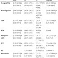
The mechanism underlying intravoxel incoherent motion (IVIM) (signal attenuation from microcirculation, indistinctionfrom thermal Brownian motion) has been demonstrated in an increasing number of scenarios within quantitative magnetic resonance imaging (MRI). As detailed elsewhere in this volume, the combination of improved hardware, software, and anatomic accessibility has (relatively recently) led to an explosion of activity for this approach throughout the body (see Fig 25.1).
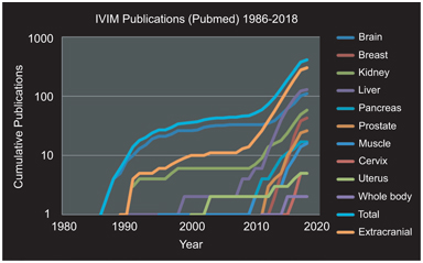
Figure 25.1 Cumulative IVIM-related publications by year overall and stratified by organ system. Three periods are evident: (i) initial discovery and investigation largely in brain tissue (1988–1998); (ii) pilot investigations in extracranial organs (1998–2008); and (iii) re-emergence and expansion of activity throughout the body (2008–present). Results were obtained via PubMed search “IVIM (or) intravoxel incoherent motion (and) (organ).” Total and extracranial categories were computed from results of the organ-specific searches.
Three periods are evident in this development: (i) an initial discovery and investigation phase, largely in brain tissue due to hardware/software availability (1988–1998), (ii) pilot investigations in extracranial organs and pathologies highly suited to vascular/ microstructural decomposition, such as hepatic and renal tissue (1998–2008), and (iii) following landmark studies in several organs [1–4] and commentary [5], rapid expansion of activity throughout the body (2008–present). The rapidly growing use of IVIM has been recognized in several recent review articles [6], for example, in the body [7, 8], in the liver [9], and in the breast [10].
As the evidence base grows, however, it has become clear that the manifestations of IVIM differentiate themselves in organ- and pathology-specific ways. The tissue fraction displaying pseudodiffusion varies greatly, necessitating adaptations of acquisition and analysis. In some cases, the microcirculation is isotropic, while in others, it shows directionality in the structure and/or flow within the flow compartment. The active processes captured in the IVIM effect are also affected by such stimuli as an exercise challenge, which has motivated protocols capturing binary or dynamic changes from the baseline. In short, the occurrences of IVIM have been recognized to require treatment beyond the static isotropic model. Just as the application of structure-based diffusion- weighted imaging contrast has evolved from isotropic to anisotropic to higher and higher levels of complexity—with associated higher biological specificity—so too can we expect that a refinement of the IVIM signature to reflect more complex scenarios will amplify diagnostic potential in those situations.
For clarity, the notation of the IVIM expressions in this chapter will be
(25.1)
where D t is tissue diffusivity, f p is perfusion fraction, and D p is pseudodiffusivity.
25.1 Phantoms
Imitation is the sincerest of flattery.
—Charles Caleb Colton
The translational pathway of successful imaging biomarkers typically involves ongoing input from synthetic phantoms to accompany experiences in vivo. Diffusion-weighted imaging biomarkers are no exception; ice-water baths have become a very reliable diffusion phantom for static isotropic diffusion [11], and polymer mixtures/ gels are also common [12–14]. A whole host of phantoms have been put forward simulating diffusion anisotropy (polymer fibers, capillaries, glass plates, and biologic phantoms) [15–22]. These systems allow controlled contrast variation, tests of reproducibility, and evaluation of new models. IVIM phantoms have also been demonstrated since the earliest uses of IVIM in clinical scanners and have grown in complexity over time (see Table 25.1 and Fig 25.2) [23–33].
Table 25.1 Summary of IVIM phantoms employed in clinical scanners
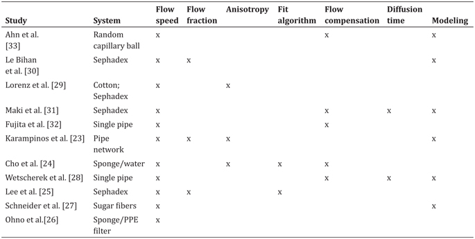
Note: Different systems were employed to generate an incoherent flow. Varying amounts of quantification, encoding, analysis algorithms, and modeling have been employed to generate and understand biomimetic flow patterns to accompany the use of IVIM within in vivo scanners.
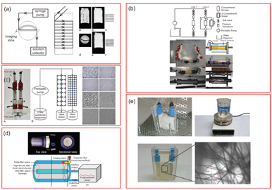
Figure 25.2 Example IVIM flow phantoms in the literature. (a) Anisotropic circumferential flow around static phantom. Reprinted from Ref. [23], with permission from John Wiley and Sons. (b) Incoherent flow through a cellulose sponge with an annular static water chamber. Reprinted from Ref. [24], with permission from John Wiley and Sons. (c) Driven flow through variable-sized Sephadex bead packs. Reprinted from Ref. [25], with permission from Wolters Kluwer Health, Inc. (d) Incoherent flow through a cellulose sponge and an annular static diffusion chamber. Reprinted from Ref. [26], with permission from John Wiley and Sons. (e) Flow through a disordered sucrose network [27].
All of these crucially employ a driven source of water motion with an incoherent flow distribution that presents a “pseudodiffusion” signal loss with diffusion-weighting magnetic field gradients. As with many fields of MRI, much inspiration for such synthetic systems was taken from nuclear magnetic resonance (NMR) research in materials science [34, 35] and adapted to the clinical MRI environment. An early synthetic IVIM phantom by Ahn et. al. [33] used a random capillary ball-shaped bundle to generate controlled incoherent flow. Another system, first demonstrated in Ref. [30] and later employed in various forms [25,29,31], was based on water flow through Sephadex microspheres. Alternatively, others [24, 26] employed cylindrical systems with a central flow compartment containing cellulose for flow dispersion and an annular space with water or gel. These systems allowed sampling of the flow or static spaces separately or in combination. Still other cases used single water pipes [28] or a network of water capillaries [23] to tease out higher-order features with a combination of advanced encoding and signal modeling. Another system [27] emulated microvasculature with a solidified sugarcane network of microcapillaries (diameters 2–25 mm). This system mimicked the interspersed microvascular and cellular volumes in real tissue and allowed the testing of higher- order quantification schemes.
This set of phantoms has simulated and tested the measurement of a variety of biological features (see Table 25.1). All of them allow control of flow rate with a corresponding change in pseudodiffusion markers, in some cases verifying a linear relationship between fluid flux and total IVIM flow (f p*D p). Another feature in some biological contexts is IVIM anisotropy, which several systems produce, given an overall flow direction in addition to transverse microcirculation [23,24,29]. In one case, a network of antiparallel flow segments produces clear anisotropy to test an “intravoxel partially coherent motion (IVPCM)” signal description, as might occur in muscle or renal tissue [23].
Another aspect of the IVIM analysis workflow is the choice of the fit algorithm, and synthetic phantoms allow the comparison of several methods (simultaneous fitting, segmented fitting, etc.) on the same data source [24, 25]. More generally, they allow testing of advanced encoding methods involving flow-compensated diffusion gradients [24,27,28,31,33] and diffusion time variation [27,28,31]. Even more broadly, complex signal models have been advanced incorporating anisotropy [36], estimating segment length or blood velocity [27, 28], or generalizing the displacement distribution [28, 37] beyond extremal cases of ballistic (short time, low velocity) and dispersive (long time, high velocity) limits.
The development of tissue-emulating (“biomimetic”) systems has practical uses not only for reproducibility and translation but also for more deep understanding of tissue contrast. The original discovery of the IVIM contrast was imagined largely as an alternative measure of tissue perfusion to contrast enhancement, which is valid, although the precise expression of the microvasculature differs between IVIM and other methods (arterial spin labeling [ASL], dynamic contrast– enhanced [DCE] MRI, and dynamic susceptibility contrast [DSC] MRI). However, the application of IVIM to many organs and contexts has revealed needs for description of microcirculation beyond perfusion (such as renal tubular flow). For all of these applications, the continued refinement of synthetic systems to accompany the in vivo assay will be vital.
25.2 Anisotropy
If you’re not sure where you’re going, you’ll probably end up somewhere else.
—Anonymous
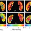
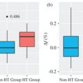
Numerous structures in the body possess anisotropic microcircula- tion, and the IVIM toolbox has progressively expanded to include this feature in clinical scanner data. One example is pseudodiffusion from vascular/tubular flow in renal (kidney) tissue, particularly in the medulla (see Fig 25.3). The “radial” pattern of tubule/duct ori- entation is well known in diffusion tensor imaging (DTI) [38–42], following an initial demonstration by Ries et. al. [43]. Intuitively, microscopic flow contributes to medullary anisotropy, as indirectly suggested by DTI studies showing elevated anisotropy when lower b values were employed [42]. Directly, several studies have now shown that the flow term shows a similar orientation pattern. One experimental demonstration employed multiple-b-value, multiple direction data to illustrate this collinear anisotropy of structural and pseudodiffusion tensors with projection plots (“peanut plot visualization”) in a combined IVIM/DTI scheme [44]. This empiri- cal view showed that pseudodiffusion anisotropy was comparable to that of the microstructure (see Fig 25.3). Another approach em- ployed an intravoxel-oriented flow (IVOF) model incorporating an apparent flow fraction tensor to capture the microcirculation and microstructural anisotropy in medullary tissue [45]. These studies have confirmed that the best representation of water transport in kidney should incorporate directionality in both flow and structural compartments. Indeed, this treatment has recently yielded diagnos- tic potential in the assessment of renal function in presurgical renal mass patients [46]. One of the measures most sensitive to asym- metric laterality in kidney diffusion—reflecting the compensatory redistribution of flow in response to the presence of a neoplasm and corresponding reduction in functioning nephrons—was axial medullary pseudodiffusion. This feature was only revealed in the com- bined IVIM-DTI analysis.
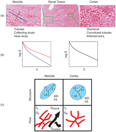
Figure 25.3 IVIM contrast in renal tissue. (a) Histological sections of the renal cortex and medulla (from Ref. [47]) show differing contributors to water trans- port; cortical tissue is an isotropic mixture of glomeruli, convoluted tubules, and vessels, while medullary tissue shows aligned tubules, vasculature, and ductal structures. (b) IVIM contrast as a function of b value shows a multicompartment response (microcirculation vs. restricted Brownian motion), with an additional component of anisotropy in medullary tissue. (c) Quantitative representations of renal DWI, with diffusion tensor indices showing structural compartments, perfusion fraction, and pseudodiffusivities (reflecting microcirculation), with the anisotropic components of D p prominent in medullary tissue.
Skeletal muscle is another organ whose microcirculation is anisotropic. Histology confirms that a large fraction of microvasculature in skeletal muscle surrounds and is aligned with each individual myofiber (see Fig 25.4). The IVIM signature in this organ is correspondingly anisotropic, as several studies have indicated [23,48,49]. One study quantified the response in an IVPCM scheme, since the perfusion component has a preferred orientation and some angular distribution around it [23]. This more complete description may aid in differentiating types of peripheral vascular disease.
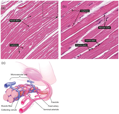
Figure 25.4 (a, b) Histologic examples from Human Protein Atlas [50] showing the alignment of capillaries with myofiber longitudinal axes in skeletal muscle. https://www.proteinatlas.org/learn/dictionary/normal/skeletal+muscle/ detail+1 (b) https://www.proteinatlas.org/learn/dictionary/normal/skeletal+ muscle/detail+1/magnification+1 (c) Diagram of skeletal muscle microvascula- ture showing close alignment of microvessels with myofibers. Reprinted from Ref. [51], with permission from Elsevier.
Related posts:
Stay updated, free articles. Join our Telegram channel

Full access? Get Clinical Tree


