TEMPORAL BONE, POSTERIOR SKULL BASE, POSTERIOR FOSSA, AND CRANIAL NERVES
TECHNICAL ASPECTS
In general, computed tomography (CT) and magnetic resonance imaging (MRI) in this anatomic region almost always require the highest possible spatial resolution, sometimes needing to balance that against required low-contrast resolution. These issues are discussed in detail in conjunction with general CT and MRI parameters in Chapters 1 through 3. General imaging parameters used in this region of interest are presented in Appendixes A and B. More refined protocols are presented when appropriate in the disease- and anatomy-specific discussions.
Ultrasound is essentially not used in this anatomic area of interest.
General applications of radionuclide and related techniques are discussed in Chapter 5.
Pros and Cons
Relative Indications for Computed Tomography and Magnetic Resonance Imaging
Patients with sensorineural and conductive hearing loss make up the bulk of temporal bone study referrals. Other common indications for CT and MRI of the temporal bone and related posterior fossa structures include facial nerve dysfunction, vertigo, tinnitus, otitis media, mass lesions in and about the temporal bone, and patients with unexplained otalgia. These general indications and others are outlined in Table 104.1, where they are keyed to the likely preferred primary study. Given different practice preferences or mitigating clinical circumstances, either CT or MRI can be an appropriate starting place for some of these indications.
CT should be the primary examination for indications that require bone detail. MRI becomes the adjunctive study where bone detail is of primary interest. As a secondary study, MRI may help characterize the nature or extent of a mass––for instance, petrous apex cholesterolosis versus phlegmon. MRI may also provide adjunctive information about the membranous labyrinth (Table 104.1).
MRI becomes the more likely primary examination when a complete evaluation of the brain stem, cerebellopontine angle (CPA), and intracanalicular course of cranial nerve (CN) VIII is necessary. The most common use of MRI is in patients with sensorineural hearing loss (SNHL) and vestibular signs and symptoms. Screening for lesions producing such dysfunction should include use of paramagnetic contrast and three-dimensional (3D) steady state images. Contrast enhancement is sometimes nonspecific. A combination of morphologic features, associated findings, and clinical settings needs to determine the next best course of action when abnormal enhancement of the membranous labyrinth, nerves, meninges, or a mass is present.
Facial nerve dysfunction may require clinical triage to determine whether CT and/or MRI are indicated at all. The clinical situation may also guide the sequencing of CT and MRI.
Patients with pulse synchronous tinnitus or a mass of possible vascular origin will often come to diagnostic imaging. These studies may establish the precise etiology of the mass or identify the cause of objective or subjective pulse synchronous tinnitus. More often, they are negative and therefore only exclusionary diagnostic efforts. However, such imaging triage can help avoid clinical misadventures––for instance, biopsy of a highly vascular mass such as a paraganglioma or injury to an important normal vessel such as the internal carotid. The primary study for this indication depends on whether there is a mass visible behind the tympanic membrane. If a mass is visible, then non–contrast-enhanced CT is done. If a mass is not visible, then a more complex contrast-enhanced CT with CT angiography and CT venography approach is necessary (Appendix A). MRI and magnetic resonance (MR) angiography are usually secondary studies for these indications as directed by non–contrast-enhanced CT or contrast-enhanced CT results and the clinical situation (Appendix B). If CT angiography and CT venography can be performed on multidetector CT, then only a single imaging study is necessary to depict middle ear, arterial, and venous causes of pulsatile tinnitus.1 Mistaking inner ear–related nonpulsatile tinnitus for pulse synchronous tinnitus is a common error in ordering of imaging studies on patients with tinnitus. The approach to these problems is very different, and this distinction must be made by the requesting physician to assure that the proper imaging approach is used.
The relative indications for CT and MRI in patients with parapharyngeal space and nasopharyngeal masses potentially involving the temporal bone is discussed in conjunction with those anatomic sites of origin of pathology.
Radionuclide studies are used primarily and sparingly for diagnosis and following treatment for skull base osteomyelitis and necrotizing otitis externa. They may also be used in the evaluation of cerebrospinal fluid (CSF) leaks (Chapter 5).
TABLE 104.1. GENERAL INDICATIONS FOR TEMPORAL BONE COMPUTED TOMOGRAPHY AND MAGNETIC RESONANCE IMAGINGa

There is essentially no role for ultrasound in these anatomic areas of interest.
Controversies
Computed Tomography Versus Magnetic Resonance for Precochlear Implant Evaluation––One Test or Both?
CT and MRI render complementary information in the preoperative assessment of cochlear implant candidates. The surgeon needs to be informed about the patency of the cochlea, cochlear and vestibular anomalies, bone dysplasias, retrocochlear disease, and anatomic variations, especially those of the facial nerve that might alter the surgical approach. CT provides information about the bony labyrinth, the vestibular aqueduct, and anatomic variants of the mastoid and vascular structures. MRI will identify cochlear and retrocochlear soft tissue abnormalities, such as cochlear fibrosis in labyrinthitis, absence or extreme atrophy of the cochlear nerve, and brain pathology along the auditory pathways. The abnormalities detected with MRI, such as cochlear patency and along the auditory neural pathway, are more likely to influence the selection of candidates and the selection of preferred side of surgery than the findings on CT.
CT and MRI should be considered especially for prelingual deafness or complex pathology. If a group prefers only CT, a routine MRI should at least be added in all cases of previously documented meningitis or prelingual deafness to establish the presence of a normal cochlear nerve. These relative values and roles of CT are currently under study, and the safest course of action seems to be doing both studies when there is a reasonable need for both.2–4
Can One Reasonably Screen SNHL Patients or those with other CN VIII Symptoms with Three-Dimensional Fourier Transform (3DFT) Steady State Sequences (CSF bright) such as CISS and FIESTA and not use Intravenous Gadolinium Enhancement?
In SNHL, the entire acoustic pathway should be carefully scrutinized to rule out cochlear and retrocochlear disease. T2-weighted imaging of the brain allows for evaluation of the brain stem, acoustic pathway, and auditory cortex. For evaluation of the CPA, the internal auditory canal (IAC), and the cochlea, both T1-weighted images before and after contrast and very thin fast spin echo T2-weighted images or a 3D gradient echo steady state sequence, such as CISS and FIESTA of the temporal bone, are mandatory.
The use of contrast will clearly increase the yield of MRI, albeit in a small but unpredictable number of cases, by demonstrating inflammatory and neoplastic labyrinthine lesions and meningeal pathology in the IAC and CPA. Although potentially visible on all sequences, contrast-enhanced T1-weighted imaging is considered the best sequence to detect CPA or IAC tumors. Middle ear and inner ear diseases such as complicated cholesteatoma and otosclerosis may cause enhancement. To diagnose acute labyrinthitis and exclude neoplastic disease, both sequences yield complementary information. In chronic labyrinthitis, fibrosis may only be depicted on T2-weighted images or 3DFT gradient echo sequences in the steady state.5
What is the Utility of Measurements Such as Bony Island Within the Lateral Semicircular Canal (LSCC) and Cochlear Height for Detecting Subtle Developmental Inner Ear Abnormalities?
Over the decades since the start (1960s and 1970s) of detailed sectional temporal bone imaging with multidimensional x-ray tomography, several measurements have been advocated in the evaluation of SNHL:
- The width of the IAC, measured on CT, is correlated with hearing loss. A narrow IAC (≤2 mm) reflects the risk of cochlear nerve aplasia. However, in cases of cochlear nerve hypoplasia, the development of the IAC is normal. MRI provides a means to visualize CN VIII directly.
- An enlarged vestibular aqueduct defines a population at risk for sudden or progressive hearing loss. The size of the vestibular aqueduct should not exceed 1.5 mm at its midportion. As a “screening” observation, the diameter should clearly appear to exceed the diameter of the adjacent semicircular canal, and any vestibular aqueduct exceeding that screening observation should be measured.
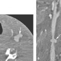
- Measurements of the cochlear and vestibular systems contribute to the detection of cochlear and/or vestibular dysplasia. Whereas gross inner ear abnormalities are detected by visual inspection only, milder dysplasias can be overlooked. Thus, the latter are often missed, although they are more prevalent. To increase sensitivity, radiographic measurements of the cochlear height on coronal images and of the LSCC bony island width should be performed. The height of a normal cochlea ranges from 4.4 to 5.9 mm. Cochlear hypoplasia (<4.4 mm) is associated with SNHL. Dimensions of the bony island of the LSCC <2.6 mm are consistent with dysplasia. There is no consistent correlation between LSCC abnormalities and SNHL (Fig. 104.1). Measurements above the range of normal for these structures may have no practical benefit in identifying inner ear dysplasias.6

FIGURE 104.1. A, B: Standardized measurements of the inner ear on temporal bone computed tomography. The cochlear height is measured in a coronal section at an oblique angle (line). The lateral semicircular bony island width is measured on an axial image on a line connecting the apex of the canal’s turn to the midpoint of the communication between the canal and the vestibule (line). C: Dysplasia of the lateral semicircular canal. The bony island measures 1.3 mm.
Modern imaging is constantly improving. Anatomic abnormalities such as incomplete cochlear partition, modiolar deficiency, and/or an abnormal cochlear nerve aperture to the cochlear base may be observed independent of an abnormal measurement such as the cochlear height. A small cochlear aperture at the base of the modiolus may identify a hypoplastic CN VIII. Normal measurements do not exclude dysplasia; they are only another tool in a multifactor risk assessment for dysplasia. A complete assessment for inner ear dysplasia should use a limited number of measurements in addition to observations for subtle dysmorphic features such as those just mentioned. With such a system, anatomic imaging will provide a reasonable but still imperfect means for such screening until better tools such as genetic screening take over or augment anatomic observations at some point.
Is There Any Real Value of MRI in Middle Ear Acquired Cholesteatoma Versus Other Erosive Disease?
The value of MRI in the evaluation of chronic ear disease, in particular cholesteatoma, is still a matter of debate. CT remains the first line technique in the pre- and postoperative assessment of suspected or residual/recurrent cholesteatomas. MRI has an additional role in the preoperative evaluation in cases of cholesteatoma-caused complications, such as labyrinthitis, encephalocele, facial palsy, sinus thrombosis, otitic hydrocephalus, brain abscess, and iatrogenic injuries. Reports on its role in uncomplicated cholesteatoma are sparse. Diffusion-weighted imaging (DWI) has been shown to be useful in the differentiation of acute otitis and cholesteatoma, but data on DWI in chronic otitis is not available.7
In the case of complete opacification of the tympanomastoid cavities on postoperative CT, it is not possible to differentiate residual/recurrent cholesteatoma from scar tissue. There is growing evidence in the literature that delayed contrast-enhanced T1-weighted imaging (30 to 45 minutes after contrast injection8) and echo planar imaging or fast spin echo DWI enable the depiction of residual/recurrent cholesteatoma. The high signal intensity on DWI and lack of enhancement differentiates cholesteatoma from granulomatous/noncholesteatomatous tissue. Disease <5 mm, however, may be missed.9–11
Is There a Useful and Reliable Correlation Between Vascular Loops in the ICA as Seen on Imaging and Unilateral Auditory Symptoms?
Unexplained unilateral hearing loss, tinnitus, vertigo, and Ménière disease have been attributed to neurovascular compression of CN VIII by a loop of the anterior inferior cerebellar artery (AICA) within the IAC. Anatomic studies12 and radiologic studies13 have not been able to confirm a correlation between the presence of an AICA loop within the IAC and auditory symptoms and have considered it a normal anatomic variation. On the other hand, several reports14,15 of successful surgical neurovascular decompressions support the existence of the AICA syndrome.
The reason for this discrepancy might be the variability of the depth of extension into the IAC. Loops may be identified on MRI and classified based on their depth into the IAC. A significant association has been found with AICA loops extending up to 50% and particularly beyond 50% of the IAC and unilateral hearing loss, whereas loops confined to the CPA showed no significant association.16 In case of unexplained unilateral hearing loss, attention should be paid to the course of the AICA; however, the diagnosis of a neurovascular causation of CN VIII symptoms should not be made on imaging alone (Fig. 104.2).

FIGURE 104.2. Possible neurovascular compression in a patient with unilateral sensorineural hearing loss. Axial magnetic resonance image (CISS) at the level of the internal auditory canal (IAC) shows the anterior inferior cerebellar artery extending deep into the IAC.
Is Imaging Necessary in Cases of Acute Facial Nerve Palsy?
The first step in evaluating patients with acute facial nerve paralysis is to determine whether the paralysis is central or peripheral. In case of central weakness, brain MRI is recommended to evaluate for ischemia and infectious or inflammatory disease. In most cases of peripheral weakness, no cause will be found; this is Bell palsy, and immediate imaging is not indicated unless other CN deficits develop indicating more widespread disease, a facial twitching or spasticity preceded or accompanying the palsy indicating continuous facial nerve irritation suggestive of a tumor, there is no recovery 3 to 6 weeks after the onset of symptoms, or the palsy recurs after partial or complete resolution. All of these atypical features suggest the possibility of a more serious cause, such as a benign or malignant neoplasm rather than the usual viral neuritis.
There are contradictory reports on the value of quantitative contrast-enhanced MR in an early phase as a predictive factor for the outcome.17,18 Although MRI can be performed earlier than electrodiagnostic studies, clinically the extent and rate of nerve degeneration measured by electroneurography are used as predictive factors.19
NORMAL ANATOMY
Parts of the Temporal Bone
The temporal bone is composed of several parts and one joint surface (Fig. 104.3A,B). The osseous parts include the mastoid portion, the petrous portion housing the inner ear, the tympanic portion forming much of the external auditory canal (EAC), the styloid process, and the squamous portion. The petrous forms the lateral floor/wall of the posterior fossa and together with the squamous forms the posterior inferior and lateral surfaces of the middle cranial fossa (Fig. 104.3C). Each petrous ridge serves as an attachment for the leaves of the tentorium cerebelli. The rigidity of the mastoid and petrous bones serves an important protective function for the senses of hearing and balance. Significant external and internal temporal bone anatomy and relevant spatial relationships will be discussed in the following sections. At the outset, it is useful to have a basic frame of reference for the temporal bone anatomy as suggested in Figures (140.3C–F).
Mastoid
The mastoid is a confluence of the petrous and squamous portions and as such is interposed between the petrous, tympanic, and squamous portions of the temporal bone and the occipital bone. Junctional sutures include the occipitomastoid and the tympanomastoid. The sutures are often asymmetrically fused, and wormian bones may be present in this location; these variations can simulate fractures of the skull base both on plain radiographs and CT. The posterolateral aspect of the mastoid abuts the sigmoid sinus; the bone separating the sigmoid sinus from mastoid air cells is called the sigmoid plate. Rarely, broad dehiscence of the sigmoid plate is seen as a normal anatomic variation (Fig. 104.4). Smaller focal dehiscence is also very uncommon as a normal variant. When imaged in a sagittal plane, the anteroposterior width or sagittal dimension of the mastoid is determined by the distance between the sigmoid plate posteriorly and either the tympanomastoid suture more superficially or the vertical portion of the facial canal more mesially. Normally, this sagittal mastoid dimension measures over 1 cm, unless there is underdevelopment of the mastoid air cells. This distance is used to define anterior displacement of the sigmoid sinus (Fig. 104.5A,B).
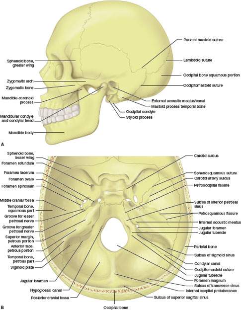


FIGURE 104.3. A, B: Gross osteology perspectives of perspectives of the temporal bone relative to the skull base and calvarium. C: Basic relationship of the temporal bone to the skull base considered schematically with an “X” drawn through the sella at the center and the temporal bone wedge basic relationship to the rest of the skull established as labeled. D–F: General schematic internal organization of the temporal bone to establish the basis of the relative positions of its major anatomic components, including the relationships of inner ear (D), facial nerve (E), and middle ear structures (F) to what is basically a triangular wedge of bone within the central and posterior skull base.
The superior surface of the mastoid partially forms the floor of the middle cranial fossa. Beneath this portion of the mastoid are the attic (epitympanic recess of the middle ear cavity) and the mastoid antrum (Fig. 104.6A,B). This bony roof covering the mastoid antrum and epitympanic recess is often very thin and frequently appears incomplete or dehiscent. The slope of the tegmen is variable. A low-lying tegmen–– defined as one that encroaches on or falls caudal to the tympanic ring, especially along the lateral aspect of the tegmen––will narrow the surgical field in mastoid approaches (Fig. 104.7A,B). The dura beneath the temporal lobe lies just above the thin roof of the middle ear or tegmen tympani and roof of the mastoid or tegmen mastoideum. The vein of Labbé is an important venous pathway that courses above the roof of the middle ear and mastoid as it drains toward the transverse sinus. This spatial relationship helps explain the possibility of temporal lobe venous infarction secondary to mastoid inflammatory disease in cases where thrombus in the transverse sinus propagates into the vein of Labbé.
Moving from lateral to medial, important landmarks along the inferior mastoid include the mastoid process or tip, the digastric groove, and the stylomastoid foramen. The sternocleidomastoid muscle attaches to the tip of the mastoid process. Medial to the mastoid tip is a groove where the posterior belly of the digastric muscle attaches. The stylomastoid foramen, the exit foramen for the facial nerve, lies just medial to the digastric groove. The posterior belly of the digastric muscle is one of the surgical landmarks for identifying the course of the facial nerve. There is a fat pad filling the space between the digastric muscle laterally and the petrous bone through which the CN VII will pass before entering the parotid gland. This stylomastoid fat pad is an excellent CT and MRI landmark for localizing the facial nerve following its exit from the skull base (Fig. 104.8A–I).

FIGURE 104.4. A: Computed tomography showing the close relationship between the mastoid and the sigmoid sinus. B: Rarely, dehiscence of the sigmoid plate can be seen as an anatomic variant.

FIGURE 104.5. Anterior position of the sigmoid sinus as examined on sagittal computed tomography images. The anteroposterior width between the sigmoid plate and either the tympanomastoid suture (A) or the descending portion of the facial nerve (B) is measured (white line). Normal values are $1 cm.
Mastoid air cell development and middle ear anatomy are discussed in a following section.
Petrous Bone
The petrous bone is pyramidal in shape with an anterior, posterior, and inferior surface. Its base converges with the squamous bone to form with the mastoid bone, and its apex abuts the sphenoid and the basiocciput at the petroclival fissure or junction. Because of these relationships, the petrous portion of the temporal bone may be considered part of the “central skull base”; such alternate designations reflect the particular focus of pathoanatomic discussion. The petrous bone joins the mastoid without an apparent fusion line. Air cells of the mastoid are confluent with those of the petrous apex. The anterosuperior surface of the petrous bone is supratentorial, while its posterior surface is infratentorial. The anterior petrous surface joins with the anterior surface of the mastoid and with the greater wing of the sphenoid to form the floor of the middle cranial fossa. The posterior petrous surface forms the anterolateral aspect of the posterior fossa (Figs. 104.3 and 104.4). At the junction between the petrous apex and the clivus, called the petroclival fissure, there is a groove formed by the inferior petrosal sinus as it drains from the posterior aspect of the cavernous sinus to the jugular vein (Fig. 104.9).
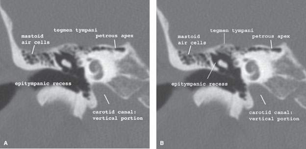
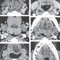
FIGURE 104.6. Coronal computed tomography images from anterior (A) to posterior (B). The bony roof of the mastoid consists of the tegmen tympani and the tegmen mastoideum. It is part of the middle cranial fossa and separates the middle ear and antrum from the temporal fossa.

FIGURE 104.7. Coronal computed tomography image (A) and T1-weighted magnetic resonance image (B) through the mastoid. A low-lying tegmen mastoideum causes overhanging temporal dura, making surgical access more difficult.


FIGURE 104.8. Anatomic drawing (A) and coronal (B–H) and axial (I–L) computed tomography images illustrating important landmarks identifying the course of the facial nerve related in part to how it is localized at surgery. Images (B) through (E) move posterior to the descending facial canal, while (G) and (H) are anterior. Images in (I) through (L) proceed from the stylomastoid foramen inferiorly. Cranial nerve VII (the asterisk shows its expected position as discussed in the text) runs through the stylomastoid fat pad, and its extracranial divisions show a close relationship to the mastoid tip and the attached muscles.
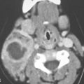
The inferior surface of the petrous bone contains a foramen for the internal carotid artery. Posterior and slightly more lateral to the carotid foramen is the jugular foramen, a cleft separating the petrous bone and the occipital bones. The jugular foramen or fossa actually has two parts separated incompletely by an osseous jugular spur or spine. The more medial and smaller of the two compartments contains the terminus of the inferior petrosal sinus and the glossopharyngeal nerve (CN IX). The more lateral of the two is larger and contains the jugular bulb, vagus nerve, and spinal accessory nerve. The tiny inferior tympanic canaliculus lies between the jugular fossa and vertical segment of the carotid canal; it contains the Jacobson nerve, which is a branch of the glossopharyngeal nerve. The internal carotid artery traverses the petrous bone within the carotid canal. This canal has a proximal vertical segment, a genu, and a distal horizontal segment. The internal carotid artery exits the petrous apex by turning superiorly as it passes above the cartilage that fills the foramen lacerum. The carotid canal lies just superior and medial to the proximal bony and cartilaginous portions of the auditory tube (Fig. 104.10).
The infratentorial surface of the petrous bone has several openings, the most prominent of which is the IAC. Others include openings for the cochlear and vestibular aqueducts and the subarcuate artery. The opening for the cochlear aqueduct lies just inferior to the IAC and that for the vestibular aqueduct is seen as a slitlike structure just lateral to the IAC.
The IAC contains neurovascular structures, CSF, and meninges. CSF within the IAC connects directly with fluid within the CPA cistern (Fig. 104.11). The cranial aspect of the IAC has a smooth wall. However, at the fundus (its more lateral aspect), the canal is partially subdivided by a curvilinear horizontal bone plate, the crista transversalis or falciformis, along its anterior wall. The anterosuperior compartment contains the facial nerve and nervus intermedius; the facial nerve then continues its course through the petrous bone by entering the labyrinthine segment of the facial canal. The Bill bar is a prominent ridge of bone and surgical landmark along the superolateral aspect of the IAC, identifying the transition of the facial nerve from its canalicular to labyrinthine segments (Fig. 104.12). The posterosuperior compartment of the IAC contains the superior vestibular nerve, while the inferior compartment contains both the cochlear nerve anteriorly, beneath the facial nerve and inferior vestibular nerve posteriorly, beneath the superior vestibular nerve. The facial nerve and the superior vestibular nerve show a parallel course within the IAC, whereas the cochlear nerve and inferior vestibular nerve are V shaped (Fig. 104.13). The cochlear nerve enters the cochlea and winds around the modiolus. The superior and inferior vestibular nerves continue on to the vestibule; a branch of the inferior vestibular nerve, the singular nerve, travels in a slitlike canal to reach the ampulla at the posterior semicircular canal. Details of the middle ear, the inner ear, and the course of the facial nerve will be presented in following sections. The shape and course of the IAC is variable without only uncommon relationships to hearing loss (Fig. 104.14).
There are other common variations of the anatomy of the petrous bone that can lead to interpretive difficulties, especially on MRI. These include the following:
- Variations in aeration, fatty marrow content, and venous lakes within the petrous apex. These variations can lead to a markedly asymmetric appearance of the petrous apices and mistaken diagnoses of mass lesions or other pathologies such as cholesterolosis, epidermoid tumors, and petrous “apicitis” (Figs. 104.15A–C and 104.16A,B).
- Arachnoid granulations that may produce areas of remodeling along the temporal bone surfaces that can be mistaken for erosive lesions (Fig. 104.17A–D). These can be a source of CSF leakage into adjacent aerated portions of the temporal bone.
- Variations in the size of the jugular fossa. The jugular fossae (Fig. 104.18A–G) are, as a rule, asymmetric and usually high, or large jugular fossa may be mistakenly interpreted as evidence of a jugular fossa tumor. A high jugular bulb is more frequently seen on the right side. This may possibly be related to the amount of blood flow difference due to drainage dominance between the right and left transverse sinuses and jugular veins.
In radiologic and anatomic studies, several definitions for a high jugular bulb are given. A jugular bulb has been referred to as high if it is lying above the level of the tympanic annulus,20 if it abuts the round window niche, or when it extends superior to the internal acoustic canal. Due to this, reported incidences of high jugular bulb vary considerably. Its importance depends on the chosen surgical approach. If the jugular bulb projects into the middle ear, the vein can be injured during middle ear surgery (e.g., cholesteatoma removal from hypotympanic retrofacial air cells) and during elevation of a tympanomeatal flap or myringotomy. As soon as the jugular bulb reaches the level of the internal acoustic canal, it will block the access to the IAC for translabyrinthine or suboccipital removal of vestibular schwannoma.
If the bony plate covering the jugular bulb is even partially absent, it is referred to as a dehiscent jugular bulb, posing more risk to preoperative injury. Rarely, a jugular diverticulum can be seen.
- Variations in signal intensity in the jugular bulb because of flow-related artifacts. This problem is compounded by the injection of paramagnetic contrast that emphasizes flow-related artifacts in these regions of complex, relatively slow flow (Fig. 104.19).

FIGURE 104.9. On the anatomic drawing (A), the venous drainage of the cavernous sinus by the superior and inferior petrosal veins to the jugular vein is shown. Both the superior and inferior petrosal veins can cause a groove in the roof of the petrous bone and at the petroclival fissure, the former seen on axial CT images (B) and (C).


FIGURE 104.10. A: Diagram showing the rather complex neurovascular relationships within and around the carotid canal and jugular fossa. B–I: Axial computed tomography images from inferior to superior (B–E) and coronal images from anterior to posterior (E–I) through the internal carotid artery and internal jugular vein and their respective canals.
Zygomatic and Squamous Bones
The zygomatic process of the temporal bone projects anteriorly from its base toward the zygomatic process. The two combine to form the zygomatic arch (Fig. 104.3). The soft tissue space between the zygomatic arch and the lateral skull/lateral orbit is the (superficial) temporal fossa. The relatively wide base of the zygomatic portion of the temporal bone forms the main buttress for the zygomatic arch. The temporomandibular joint (TMJ) is located along the base of the zygomatic part of the temporal bone. The details of TMJ anatomy are discussed in Chapter 4.
The squamous portion of the temporal bone forms much of the lateral wall of the middle cranial fossa. External to this bone is the superficial temporal fossa; the temporalis muscle and fat fill the superficial temporal fossa. A vertical linear groove in the outer table of the squamous part of the temporal bone is created by the course of the anterior deep temporal artery. This groove may be misinterpreted as a fracture on lateral skull radiographs. The inner table of the squamous portion of the temporal bone contains a groove for the posterior division of the middle meningeal artery.
Tympanic Bone and External Auditory Canal
The EAC is essentially a 2.5-cm–long cylinder formed by tympanic bone medially and cartilage laterally (Fig. 104.20). The cartilaginous anterior wall is normally pierced by two or three vertical fissures (of Santorini); these are a potential route for spread of pathology between the EAC and parotid gland but are not routinely visible on CT or MRI. The EAC joins the mastoid and petrous portions of the temporal bone at the tympanomastoid suture and petrotympanic fissure, respectively. The mesial aspect of the tympanic bone is separated from the middle ear cavity by the tympanic membrane. The forward angulation of the tympanic membrane results in the anterior EAC wall being about 6 mm longer than the posterior wall. The insertion of the tympanic membrane annulus around the mesial aspect of the tympanic bone is sometimes called the tympanic sulcus (Fig. 104.21). The pinna and cartilages of the external ear surround the ostium or meatus for the EAC. The central part of the external ear is formed by the tragal cartilage. On imaging studies, the deeper aspect of the tragal cartilage, at its junction with the cartilaginous part of the EAC, can be identified; this part has been nicknamed the “tragal pointer” by surgeons. The tragal pointer is a surgical landmark used to identify the main trunk of the facial nerve; the trunk is usually approximately 1 cm inferior and medial to the tragal pointer. On CT and MRI, the tragal pointer is seen as an angulated segment of the cartilaginous EAC about 1 cm from the bony cartilaginous junction (Fig. 104.8).
Slight irregularities of the tympanic bone are commonly seen on CT at the bony-cartilaginous junction of the EAC. In well-aerated temporal bones, the posterior wall of the canal may normally appear thin or dehiscent. A small gap in the anteroinferior portion of the tympanic bone is a common normal variant called the persistent foramen tympanicum or foramen of Huschke21 (Fig. 104.22). Fat and other portions of the TMJ capsule can rarely herniate into this and present as an external canal mass. A great variability in the configuration of the EAC is seen (Fig. 104.23).

FIGURE 104.11. Drawing showing contents of the internal auditory canal and their relationship to the inner ear and brain stem. The appreciation of the location of cranial nerve nuclei in the brain stem and then the peripheral course of the nerve through its related cistern and exit foramen to its end point of innervation is a fundamental concept in evaluating any cranial neuropathy.
Middle Ear or Tympanic Cavity
The tympanic cavity is divided, somewhat arbitrarily, into three intercommunicating parts: the epitympanum, the mesotympanum, and the hypotympanum, corresponding, respectively, to the superior, middle, and inferior levels of the middle ear cavity (Figs. 104.24 and 104.25).
The epitympanum communicates anteriorly and superiorly with the anterior epitympanic recess; the floor of the recess forms the roof of the epitympanum. More posteriorly, the roof of the middle ear cavity (tegmen tympani) is simply the roof of the epitympanum. The mesotympanum is bounded medially by the otic capsule and laterally by the tympanic membrane. The hypotympanum is bounded inferiorly by the floor of the tympanic cavity that overlies the jugular fossa posteriorly and the lateral aspect of the carotid canal anteriorly. The hypotympanum opens anteriorly, forming the bony portion of the auditory tube; the more distal, cartilaginous portion, of the tube eventually connects the middle ear to the nasopharynx. This portion is only visible if containing air (Figs. 104.25 and 104.26). The middle ear cavity is about 1.5 cm in its vertical and anteroposterior dimensions. From a central constriction of about 2 to 3 mm in the mesotympanum, it expands to a transverse dimension of 6 mm in the epitympanum and 4 mm in the hypotympanum.


FIGURE 104.12. Normal axial (A–L) and coronal (M–S) computed tomography anatomy of the internal auditory canal, vestibular aqueduct, cochlear aqueduct, subarcuate canal, and singular canal.
Related posts:
 Preseptal Compartment: Acute and Chronic Infections and Noninfectious Inflammatory Conditions
 Necrotizing (“Malignant”) Otitis Externa
 Cervicothoracic Junction: Brachial Plexus Trauma
 Oropharynx: Introduction
 Branchial Apparatus Developmental Anomalies
 Mandible and Maxilla: Odontogenic Tumors and Cysts
Stay updated, free articles. Join our Telegram channel

Full access? Get Clinical Tree


