Cervical Spine Checklists
 1
1
Radiographic examination
Minimum necessary views
Lateral cervical spine to include T1
AP cervical spine
AP open-mouth odontoid
CT examination: minimum necessary
Axial, sagittal, and coronal noncontrast images in bone algorithm
Extending through at least the level of T1
Axial and sagittal images in soft tissue algorithm
 2
2
Common sites of injury in adults
Craniocervical junction (Skull base – C2)
Fractures
Occipital condyle
Atlas – C1
Posterior arch
Jefferson fracture – fractures of ring anterior and posterior
Anterior arch
Axis – C2
Odontoid (dens)
Body
Extension of dens fracture
Teardrop fracture
C2 pars interarticularis fractures – hangman’s fracture
Dislocations/subluxation
Atlanto-occipital dissociation
Atlanto-axial dislocation
Lower cervical spine (C3-C7)
Fractures
Vertebral bodies
Compression, distraction, and translation/rotation injuries (SLIC)
Simple compression, anterior wedge
Teardrop
Vertical sagittal split of vertebral body
Burst
Lateral mass
Facets
Articular mass
Transverse process
Spinous process
Traumatic disc injuries
Dislocations/subluxations
Teardrop fracture dislocation
Distraction – ligament disruption
Intervertebral disc, joint capsules, and interspinous ligament
Anterior and posterior longitudinal ligaments
Facets – unilateral or bilateral – rotation, shearing injuries
Subluxed
Perched
Dislocated
 3
3
Special considerations in the elderly
Odontoid fractures common
Often combined with C1 arch fractures
Spinal cord injury in presence of significant degenerative arthritis and disc disease
Often with either subtle or even without overt radiographic abnormality (SCIWORA)
Hyperextension teardrop
Fracture of inferior or superior anterior margins of vertebral body
Fracture of osteophyte at superior or inferior anterior margin of vertebral body
Fractures in DISH (diffuse idiopathic skeletal hyperostosis)
 4
4
Common sites of injury in children and adolescents
Cervical spine injury ( CSI) rare in children under 8 years of age
Relatively more involve upper cervical spine
Craniocervical dissociation
C1 fractures
Dens fractures uncommon in children
Rare – apophyseal separations of synchondrosis between dens and body of C2
Spinal cord injury without radiographic abnormality (SCIWORA)
At and beyond 14 years of age injuries similar to those of adults
Relatively more involve lower cervical spine, C4-C7
Vertebral body
Compression fracture
Teardrop fracture dislocation
 5
5
Injuries likely to be missed
Subtle fractures on radiography – need CT
Nondisplaced odontoid fractures
Facet fractures
Occipital condyle fractures
 6
6
Where else to look when you see something obvious
Avoid “satisfaction of search.”
Find an injury at one level: closely evaluate the entire cervical spine above and below.
Multilevel discontiguous spine fractures
Fractures of C1 and C2 often associated with fractures of the lower cervical spine (C4-C7)
Two- or three-level fractures encountered in 20% of spinal fractures
CT entire T and L spine after identifying fracture of C-spine
Find a compression fracture: look for associated posterior element injury.
Find a vertebral body injury: look for bony compromise of spinal canal.
Find a facet malalignment on one side: look for contralateral facet malalignment/fracture.
 7
7
Where to look when you see nothing at all
Obtain an MRI for those with neurologic signs and symptoms.
Spinal cord contusion
Herniated nucleus pulposus (HNP)
Spinal cord injury without radiographic abnormality (SCIWORA)
Check width of spinal canal for spinal stenosis.
Spondylosis and degenerative changes in elderly
Check for evidence of hyperextension injury.
Teardrop fractures at anterior margins of vertebral bodies
Anterior widening of disc space
Prevertebral soft tissue swelling
Review images.
Spinolaminar line
Interspinous distances
Closely evaluate prevertebral soft tissues for swelling.
Look for subtle fractures.
Facets
Transverse processes
Spinous processes
Cervical Spine – The Primer
Preamble: Imaging Spinal Trauma
Though traditional and long the mainstay of cervical spine evaluation, radiographs of the cervical spine now have a limited role in the initial assessment of cervical spine trauma. Computed tomography (CT) was first introduced in the 1970s but did not prove adequate for the evaluation of the acutely injured spine until the early 2000s with the introduction and perfection of multidetector CT (MDCT), with rapid exposures coupled with the development of immediate and readily accomplished multiplanar image reconstructions. This permitted coronal and sagittal reconstructions of the entire length of the cervical spine in addition to the standard axial images. With these advances it became apparent that MDCT is more accurate and more efficient in the detection and depiction of spinal injuries.
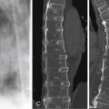
The comparative difficulty of detection by radiography is shown by a fracture of the dens that is hard to see, if not impossible to identify, on the lateral cervical spine radiograph ( Figure 6-1 A ) but is clearly shown by the MDCT sagittal reconstruction ( Figure 6-1 B ). The associated fracture of the posterior arch of C1 is seen by both examinations ( Figure 6-1 A, C) .

It has been shown that up to 20% or more of cervical fractures disclosed by MDCT are unapparent, overlooked, or simply missed on plain film radiographs of the cervical spine. Thus, the American College of Radiology Appropriateness Criteria: Suspected Cervical Spine Injury states that MDCT, not radiography, is now the primary, preferred, and most appropriate method of imaging suspected cervical spine injury in patients older than 14 years.
Guidelines for imaging potential cervical spine injury (CSI)
There has long been professional and public concern about the overuse of radiography and computed tomography (CT) and the resultant excessive radiation exposure in patients with CSI. Two separate clinical guidelines that allow for triage of patients with suspected CSI have gained general approval: the NEXUS (National Emergency X-Radiography Utilization Study) criteria and the Canadian Cervical Spine Rule (CCR). Though written to address the indications for radiography in cervical spine trauma, they are equally applicable for computed tomography. Both the NEXUS and Canadian Cervical Spine Rule are recognized as valid by the American College of Radiology Appropriateness Criteria: Suspected Cervical Spine Injury. Use of one of these clinical decision rules is recommended to avoid excessive use of cervical spine imaging.
The rules are different for pediatric patients. In patients under age 14, radiography remains the examination of choice and is recommended by the ACR Appropriateness Criteria. This is done for two primary reasons: There is a relatively low incidence of CSI under the age of 14 and a strong desire to limit the radiation exposure dose from CT in younger individuals. However, cervical spine MDCT (multidetector CT) remains as the initial diagnostic modality for all patients age 14 and older because the incidence of CSI approaches that of adults.
NEXUS
The NEXUS criteria allow the physician to forego imaging entirely when certain criteria are met. The patient does not require imaging if there is
No midline cervical tenderness
No neurologic deficit
No distracting injury
Normal level of awareness (Glasgow Coma Scale [GCS] = 15)
No intoxication
Canadian Cervical Spine Rule
The Canadian Cervical Spine Rule is for alert and stable patients where cervical spine injury is a concern based on consideration of injury mechanism, patient age, and physical examination findings.
Prerequisites for this assessment
Concern for cervical spine injury
Patient alert (GCS = 15)
Patient in stable condition
High-risk factor that mandates radiography
Age ≥65yrs
Dangerous mechanism of injury
Fall from elevation ≥3 ft/5 stairs
Axial load to head (i.e., diving)
MVC high speed (>60 mph, 100 km/h), rollover, ejection
Motorized recreational vehicle
Bicycle crash
Paresthesias in extremity
Inability to actively rotate neck 45° to the right or left
Low-risk factors that allows safe assessment of range of motion
Simple rear-end MVC, but not to include
Rollover
Being pushed into oncoming traffic
Being hit by bus, large truck, or high-speed vehicle
Sitting position in the ED
Ambulatory at any time
Absence of midline cervical spine tenderness
Although CT is recommended as the primary means of imaging for the evaluation of cervical spine trauma, radiographic examinations are still ordered and obtained for that purpose. These patients usually have sustained lesser trauma and have no specific signs of cervical spine injury, thus, not qualifying for imaging under the NEXUS or Canadian Cervical Spine Rule guidelines. Such patients may not have sought care until several days after the injury but now do so because of continued and/or increasing pain in the neck and limitation of motion. The NEXUS criteria and Canadian Cervical Spine Rule notwithstanding, the examining physician feels compelled to obtain a radiographic examination of the cervical spine to dispel the patient’s anxiety, meet the “patient’s expectations” of proper care under the circumstances, as well as to demonstrate the physician’s concern for the patient and mollify potential liability concerns. The vast majority of such examinations obtained under these circumstances will show nothing more than straightening of the cervical spine due to muscle spasm without fractures or dislocations. These should be reported as “No evidence of fracture or dislocation” with the added comment, “If pain persists, a repeat examination should be obtained in 7 to 10 days. If pain is severe, consider CT examination to disclose occult fracture.”
 1
1
Radiographic examination
Minimum necessary views
Lateral cervical spine to include T1
AP cervical spine
AP open-mouth odontoid
The radiographic examination of the cervical spine should include a minimum of three views: lateral ( Figure 6-2 A ), AP ( Figure 6-2 B ), and AP open mouth of C1/C2 ( Figure 6-2 C ). Fractures and dislocations are best visualized on the lateral projection ( Figure 6-2 A ). Rotational injuries and fractures of the lateral masses may be evident on the AP projection ( Fig 6-2 B ). A few fractures of the ring of the atlas (C1) and the dens of the axis (C2) may be better visualized on the AP open-mouth view ( Figure 6-2 C ).
Pattern of search: Lateral radiograph ( Figure 6-3 A )
Basion-dens interval
Atlanto-dens interval
Alignment of spine ( Figure 6-3 B )
Anterior spinal line (solid red line)
Posterior spinal line (dashed red line)
Spinolaminar line (dotted red line)
Interspinous distance (red dots)
- •
Vertebral bodies configuration and alignment
- •
Facet joints configuration, width and alignment
- •
Prevertebral soft tissues
- •
Pattern of search: AP radiograph ( Figure 6-4 A, B )
- •
Alignment of spinous processes (thin red line)
- •
Alignment of vertebral bodies (thick red lines)
- •
Interspinous distance (red dots)
- •
Undulant, smooth contour of the articular pillars (arrows)

FIGURE 6-4
A, B, AP radiograph.
- •

FIGURE 6-3
A, Lateral radiograph. B, Alignment of spine.
| Open mouthed odontoid ( Figure 6-5 C ) | Lateral view C1/C2 ( Figure 6-5 D ) |
|---|---|
| Lateral alignment of C1-2 (short red lines) | Clivus-dens interval (1-1.3 cm) |
| Atlanto-dental interval (thick red lines) | Clivus-dens alignment (vertical red line) |
| Dens | C1 anterior arch-dens interval (broken red circle) |
| C2 body | Width of C2 and C3 (red line in C2-3 disc) |
| Occipital condyle | Prevertebral soft tissues |

Computed tomography (MDCT)
MDCT has superseded radiography for the initial assessment of older teenagers and adults because of the accuracy and ease of detecting injuries by MDCT in comparison to radiography. Therefore, when imaging is indicated, cervical spine MDCT is the initial diagnostic modality in all patients age 14 and older.

CT examination: Minimum necessary
Axial, sagittal, and coronal noncontrast 2 mm or thinner images in bone algorithm
Extending through at least the level of T1
Axial and sagittal images in soft tissue algorithm
Having a well-defined and consistent search pattern for cervical spine evaluation will allow rapid identification of cervical injuries in the trauma patient. The minimum should include follow:
Sagittal CT search pattern ( Figure 6-6 )
- •
Right atlanto-occipital (occipital-C1) and atlanto-axial (C1-C2) joints ( Figure 6-6 A, B )
- •
Right lateral facet alignment and facet fractures ( Figure 6-6 A, B )
- •
Anterior spinal line and vertebral body heights ( Figure 6-6 C )
- •
Posterior spinal line ( Figure 6-6 C )
- •
Spinolaminar line ( Figure 6-6 C )
- •
Interspinous distances and posterior spinous processes ( Figure 6-6 C )
- •
Midline craniocervical junction alignment ( Figure 6-6 C )
- •
Basion-dens interval
- •
C1 anterior arch – dens interval
- •
Opisthion (posterior margin of foramen magnum) – C1 posterior arch – C2 spinolaminar junction alignment
- •
- •
Left lateral facet alignment and facet fractures
- •
Left atlanto-occipital (OC-C1) and atlanto-axial (C1-C2) joints

Axial CT search pattern ( Figure 6-7 A, B )
- 1.
Vertebral body for fractures and uncovertebral joints
- 2.
Transverse processes and transverse foramina
- 3.
Pedicles
- 4.
Facets (also referred to as articular pillars)
- 5.
Posterior arch with laminae
- 6.
Spinous process

Coronal search pattern ( Figure 6-8 A, B )
- 1.
Occipital condyles
- 2.
Facets and lateral masses (also referred to as articular pillars)
- 3.
Transverse processes
Spinous processes (not shown)

Soft tissue windows ( Figures 6-9 and 6-10 )
- •
Prevertebral soft tissues
- •
Paraspinous musculature for edema/ hemorrhage
- •
Tectorial membrane at craniocervical junction
- •
Spinal canal for disc injuries, epidural hematoma, bone fragments


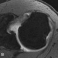
It is important to view all images in both bone and soft tissue windows. Abnormal findings in the soft tissues point to underlying bone and joint abnormalities. The normal appearance of the soft tissue anatomy at the craniocervical junction is shown in Figure 6-9 A . Note the course and position of tectorial membrane extending from the clivus to the posterior surface of the dens. The posterior longitudinal ligament lining the spinal canal is seen on the posterior surface of the vertebral bodies, and the ligamentum flavum lining the posterior surface of the spinal canal is shown on and between the anterior surfaces of the laminae ( Figure 6-9 A ). Extradural hematomas pointing to underlying bone or joint abnormalities may be identified ( Figure 6-9 B ). In this case, the bone window clearly shows subluxation of the atlanto-occipital joint ( Figure 6-9 C ) as the cause of the extradural hematoma.
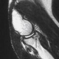
Bulging or herniated discs may be identified indicating the need for further evaluation by MRI ( Figure 6-10 ). This elderly patient sustained a type II fracture of the dens ( Figure 6-10 A ). Mid-sagittal recon soft tissue window image revealed a small hematoma about the fracture. Closer inspection revealed a rounded density at the posterior surface of the C3-4 disc space and a similar density posteriorly consistent with an enfolded, hypertrophied ligamentum flavum ( Figure 6-10 B ). The canal is constricted between these two densities. MRI confirms these findings ( Figure 6-10 C, D ). Note the herniated disc compressing the spinal cord ( Figure 6-10 D ). The spinal cord shows evidence of edema and/or myelomalacia. This proved to be important for preoperative planning. The fracture of the dens was reduced and pinned with single-screw fixation. An anterior discectomy was performed at C3-4 to relieve the pressure on the spinal cord. C3-4 was fused with placement of bone graft and a metal cage in the disc space.
Paraspinous musculature
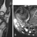
Paraspinous muscular edema is a useful sign, when present, to indicate the presence of significant injury to the cervical spine soft tissues. However, edema takes time to develop, and the absence of paraspinous muscular edema does not exclude soft tissue injury. Evaluate the paraspinous soft tissues on a narrow CT window to visualize this finding optimally ( Figure 6-11 A ), confirmed on MRI in this patient ( Figure 6-11 B ).

Magnetic resonance (MR) evaluation
Indications for MR imaging in the cervical spine have expanded in recent years. For a patient with suspected cervical spine trauma, the American College of Radiology (ACR) appropriateness criteria recommend MRI evaluation of the cervical spine in addition to MDCT, especially when ligamentous or neurologic injury is suspected. ( ACR 2013 update ). The spectrum of spinal cord injury ranges from mild edema manifested by increased T2 signal in a patient without underlying myelomalacia, to severe edema, cord hemorrhage, and transection. Extensive cord signal change or compression on MRI, in a patient with only a partial or mild neurologic deficit, indicates a spinal cord at risk for further injury and a patient in whom aggressive management is warranted.
Integrity of the intervertebral disc and associated ligamentous structures is best evaluated with MRI. The anterior and posterior longitudinal ligaments, interspinous and supraspinous ligaments are assessed, in addition to the capsular ligaments of the facets. Imaging of the intervertebral disc can be complex, with annular fissures, disk protrusions and extrusions often difficult to date. Clinical history and physical exam findings are important in determining whether a disc protrusion is acute or chronic. A comprehensive review of cervical spine MRI is beyond the scope of this primer.
 2
2
Common sites of injury in adults
Craniocervical junction (skull base – C2)
Fractures
Occipital condyle
Atlas – C1
Posterior arch
Jefferson fracture – fractures of ring anterior and posterior
Anterior arch
Axis – C2
Odontoid (dens)
Body
Extension of dens fracture
Teardrop fracture
C2 neural arch – hangman’s fracture
Dislocations/subluxation
Atlanto-occipital dissociation
Atlanto-axial dislocation
Diagrams of the craniocervical junction ( Figure 6-12 A , 6-12 B , Clivus, C1 and C2) pinpoint the common sites of fractures and dislocations in adults. The most common sites of fracture are identified by red lines. Red arrows demonstrate displacement of the lateral masses of C1 indicative of simultaneous fractures of the anterior and posterior arches of the atlas (C1). Your pattern of search should include all sites.

Craniocervical junction injuries
Occipital condyle fractures
Occipital condyle fractures indicate disruption of the alar ligament, with or without other ligaments, at the craniocervical junction. The injury may be stable (unilateral ligament involvement) or unstable (bilateral involvement).
Diagnosis : There are three major types ( Figures 6-13 and 6-14 ):
Type I: comminution of the occipital condyle without significant displacement
Type II: extension of a basilar skull fracture through the occipital condyle
Type III: avulsion of the occipital condyle with inferomedial displacement

FIGURE 6-13
A, Type I occipital condyle fracture: comminution of the occipital condyle without significant displacement. B, Type II occipital condyle fractures: extension of a basilar skull fracture through the occipital condyle. C, Type III occipital condyle fractures: avulsion of the occipital condyle with inferomedial displacement.

FIGURE 6-14
A, Type I occipital condyle fracture: comminution of the occipital condyle without significant displacement. B, Type II occipital condyle fractures: extension of a basilar skull fracture through the occipital condyle. C, Type III occipital condyle fractures: avulsion of the occipital condyle with inferomedial displacement.
Figure 6-15 is another type III fracture of the left occipital condyle shown in the axial ( Figure 6-15 A ), coronal ( Figure 6-15 B ), and sagittal ( Figure 6-15 C ) left lateral reconstruction images.

Atlanto-occipital dissociation
Mechanism
Atlanto-occipital dissociation is most commonly due to anterior dislocation of the head relative to the spine but may also be caused by longitudinal distraction or posterior dislocation. This injury is much more common in young children. Atlanto-occipital dissociation is usually fatal, particularly when widely displaced, but there are some survivors. Survival is three times more likely in children, principally in those with lesser injuries and displacement.
Diagnosis
Evaluate the alignment of the occiput relative to C1. The joint surfaces should be parallel. The width of atlanto-occipital articulation is generally ≤2 mm ( Figure 6-16 A, B ). Look for supporting findings, like soft tissue swelling at the craniocervical junction (see Figure 6-18 ) or joint asymmetry ( Figure 6-16 C, D ) compared with the contralateral side.

This patient demonstrates atlantal-occipital joint widening ( Figure 6-17 A ), posterior dislocation of the cervical spine ( Figure 6-17 B ), and an increased basion-dens interval ( Figure 6-17 C ).

An anterior atlanto-occipital dissociation, with fracture of the right occipital condyle, is demonstrated by anterior displacement of the dens and C1 ( Figure 6-18 A, B ) and an associated extradural hematoma at the foramen magnum ( Figure 6-18 B ). Note also a small avulsion from the tip of the dens ( Figure 6-18 B ). Axial ( Figure 6-18 C ) and right sagittal images ( Figure 6-18 D, E ) reveal a fracture of the right occipital condyle and anterior dislocation of the atlanto-occipital joint.

C1 ring fractures
C1 ring fractures may involve the anterior arch, the posterior arch, or both arches ( Figure 6-19 ). Fractures involving both arches are known as Jefferson fractures.

Posterior arch
Mechanism
Hyperextension of the head compressing C1 arch between occiput and neural arch of C2.
Diagnosis
The most common posterior arch fracture is a bilateral vertical fracture of the neural (posterior) arch ( Figures 6-20 and 6-21 ). However, this fracture must be distinguished from developmental defects, which have rounded, tapered, and corticated margins ( Figure 6-21 , black arrow). The latter is a congenital failure of fusion of the two limbs of the posterior arch in the midline, a common normal variant, associated with a dens fracture and bilateral fractures of the posterior arch in this patient ( Figure 6-21 ).


Anterior arch
Mechanism
Hyperextension of the head upon the neck results in the dens pressing against the anterior arch of C-1 and results in simultaneous fractures of the dens and anterior arch ( Figure 6-22 A, B ). Avulsions of the anterior longitudinal ligament and the longus colli muscle from their insertions create typically minimally displaced, horizontal fractures, often associated with dens fractures.

Diagnosis
Segmental fractures of the anterior arch that are displaced anteriorly ( Figure 6-22 A ), so-called “plough” fractures, are due to the shearing forces of hyperextension injuries in the elderly. These are commonly associated with fractures of the dens ( Figure 6-22 B ).
Jefferson fracture
Mechanism
Blow to the vertex (axial loading) as in diving into shallow water.
Diagnosis
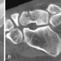
This is a comminuted C1 fracture that involves both the anterior and posterior arches with outward displacement of the fragments ( Figure 6-23 ) and commonly referred to as a Jefferson fracture. Frontal radiograph ( Figure 6-23 A ) and coronal CT images ( Figure 6-23 B ) show lateral subluxation of the lateral margins of C1 on C2 bilaterally. Axial CT image ( Figure 6-23 C ) and 3D reconstruction ( Figure 6-23 D , different patient) show two fractures in the anterior arch and one in the posterior arch.

The reverse may also occur: two fractures in the posterior arch and one in the anterior arch ( Figure 6-24 A, B, C ) or, alternatively, two fractures in each arch.

Atlanto-axial dislocation
Mechanism
Atlanto-axial dislocation ( Figure 6-25 A, B ) is said to be the most common dislocation at the craniocervical junction but is rarely due to trauma. It is more commonly associated with rheumatoid arthritis, its variants, or Down syndrome. The dislocation may also be transient secondary to ligamentous laxity associated with severe infections of the head and neck.

Diagnosis
Flexion views may be necessary to demonstrate the subluxation, which may be reduced in neutral position and extension. Normal distance of the anterior cortex of the dens to the posterior cortex of the anterior arch of the atlas:
- •
2.5 mm in adults
- •
5 mm in children
In <10% of cases, the predens space is V-shaped, widened cranially. The cranial portion of the V still usually measures <4 mm but may measure up to 7 mm and still be normal.
A widely displaced atlanto-axial dislocation in an elderly woman associated with a type II dens fracture and plough fracture of C1 are shown ( Figure 6-26 A, B, C, D ). The right ( Figure 6-26 A ) and left ( Figure 6-26 C ) facet joints are dislocated the full width of the facets posteriorly. A displaced fracture of the dens and wide, asymmetric separation between the anterior arch of C1 and dens is shown in the mid-sagittal reconstructed image ( Figure 6-26 B ). There is also a plough fracture of the anterior arch of C1 seen in the axial image ( Figure 6-26 D ).

Axis (C2)
Fractures of the odontoid process (dens fractures)
Fractures of the odontoid are common in the elderly and frequently accompanied by fractures of C1 as a result of low-impact trauma such as falls from a standing height. Dens fractures occur in younger individuals from motor vehicle accidents and other high-impact trauma but are rarely encountered in children.
Mechanism
Hyperextension of head upon the cervical spine is the most common mechanism. Hyperflexion, axial loading, and shear forces contribute in some cases.
Diagnosis
Dens fractures are popularly classified by the Anderson and D’Alonzo Classification.
Type I: (4%) an oblique fracture limited to the dens ( Figure 6-27 A )

FIGURE 6-27
A, Type I: (4%) an oblique fracture limited to the dens. B, Type II: (66%) a transverse fracture at the base of the dens. C, Type III: (30%) a fracture at the base of the dens extending into body of C2.
Type II: (66%) a transverse fracture at the base of the dens ( Figure 6-27 B )
Type III: (30%) a fracture at the base of the dens extending into body of C2 ( Figure 6-27 C )
The typical features of a type II fracture of the dens are shown ( Figure 6-28 A, B ); the fracture line is transverse at the base of the dens. Note the dens is displaced posteriorly, and a tag of the cortex of the dens extends posteriorly from the base of the dens in keeping with a hyperextension mechanism of injury ( Figure 6-28 A ).

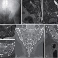
Figures 6-29 and 6-30 demonstrate the characteristic features of Anderson and D’Alonzo type III dens fractures. Note the fractures extend from the base of the dens into the body of C2. The body of C2 is comminuted, which has made the body of C2 wider than the body of C3 in one of the cases ( Figure 6-29 A, B ) and less so in the other ( Figure 6-30 A ). This widening is known as a “fat C2” and is characteristic of a type III odontoid fracture. Comminution with fracture lines extending from the base of the dens and superior facets into the bodies of C2 are well shown by axial ( Figure 6-29 D ) and coronal ( Figure 6-29 C and 6-30 B ) images.