 he femur is the longest, largest, and strongest osseous structure in the body. Because of its length, width, and weight-bearing role, it must tolerate extremes of axial loading in addition to angular and rotational stresses. The femur is surrounded by large muscle groups and an extensive vascular supply. Therefore, the major problem following fracture is not healing, but maintaining length and alignment. Fractures of the femoral head, neck, and trochanteric region were included in Chapter 4. Distal femoral and intercondylar fractures will be reviewed in Chapter 6. Limb-saving procedures for neoplastic processes will be discussed in Chapter 14.
 Trauma
Femoral shaft fractures are usually associated with high-velocity trauma such as motor vehicle accidents (90%). The incidence (2% of all skeletal fractures) is similar for adults and children. In children and adolescents the incidence is three times higher in males than females. A significant number (70%) of fractures in children younger than 3 years of age are related to nonaccidental trauma (child abuse). In patients with hip or knee arthroplasty, fractures tend to occur at the tip of the femoral components.
Associated injuries are common. Proximal shaft fractures may be associated with pelvic, femoral neck (5% to 6%), trochanteric fractures, and hip dislocations. Distal shaft fractures are more often associated with knee or tibial fractures and ligament or meniscal injuries in the knee.
Most femoral fractures involve the middle third of the diaphysis. Classification and radiographic description are based on segment involvement, rotation, angulation, and shortening. Fractures may be closed (soft tissues intact) or open (penetrating wound or fragment extrusion).
Fracture classification: Winquist/Hansen
Type I: Small comminuted fragment, >50% cortical contact by main fragments (see Fig. 5-1)
Type II: Larger comminuted fragment, >50% cortical contact by main fragments (see Fig. 5-2)
Type III: Larger comminuted fragment, with 62;50% cortical contact by major fragments (see Fig. 5-3)
Type IV: Severely comminuted with no cortical contact of main fragments (see Fig. 5-4)
Segmental transverse: Comminuted segmental transverse fractures (see Fig. 5-5)
Segmental oblique and comminuted (see Fig. 5-6)
Spiral mid-shaft fracture (see Fig. 5-7)
Proximal transverse fracture (see Fig. 5-8)
Proximal oblique fracture (see Fig. 5-9)
Proximal comminuted fracture (see Fig. 5-10)
Distal transverse fracture (see Fig. 5-11)
Distal oblique fracture (see Fig. 5-12)
Distal comminuted fracture (see Fig. 5-13)
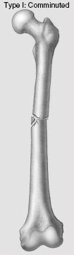
 Figure 5-1 Type I fracture: small comminuted fragment with >50% cortical contact of main fragments.
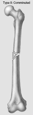
 Figure 5-2 Type II fracture: larger comminuted fragment with >50% cortical contact of main fragments.
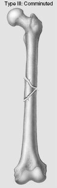
 Figure 5-3 Type III fracture: >50% cortical contact.
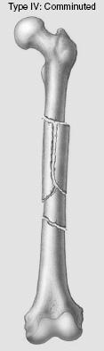
 Figure 5-4 Type IV fracture: severely comminuted with no cortical contact.
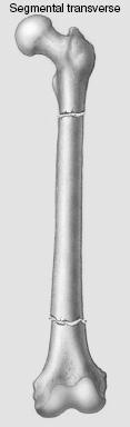
 Figure 5-5 Comminuted segmental transverse fractures.
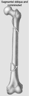
 Figure 5-6 Segmental oblique and comminuted fractures.
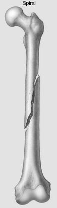
 Figure 5-7 Mid-shaft spiral fractures.
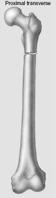
 Figure 5-8 Proximal transverse fractures.
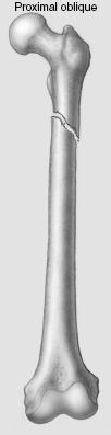
 Figure 5-9 Proximal oblique fractures.
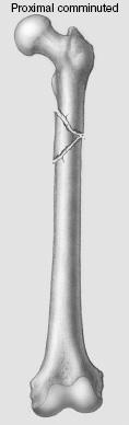
 Figure 5-10 Proximal comminuted fractures.
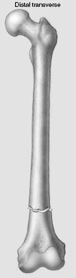
 Figure 5-11 Distal transverse fractures.
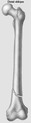
 Figure 5-12 Distal oblique fractures.
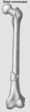
 Figure 5-13 Distal comminuted fractures.
Open fracture classification: Gustilo/Anderson
Type I: Wound clean and <1cm
Type II: Wound >1 cm without extensive soft tissue damage
Type IIIA: Extensive soft tissue wound (≥10 cm), periosteum intact
Type IIIB: More severe with periosteal stripping, bone exposure, and extensive contamination
Type IIIC: A and B plus arterial injury requiring vascular repair
SUGGESTED READING
Beaty JH. Operative treatment of femoral shaft fractures in children and adolescents. Clin Orthop. 2005;434:114–122.
Gustilo RB, Anderson JT. Prevention of infection in treatment of 1025 open fractures of the long bones. Retrospective and prospective analysis. J Bone Joint Surg. 1976;58A:543–548.
Winquist RA, Hansen ST, Clawson DK. Closed intramedullary nailing of femoral fractures. J Bone Joint Surg. 1984;66A:529–539.
Winquist RA, Hansen ST, Clawson DK. Closed intramedullary nailing of femoral fractures: A report of 520 cases. J Bone Joint Surg. 2001;83A:1912.
 Preoperative Imaging
Standard radiographs (computed radiographic [CR] images) of the femur include anteroposterior (AP) and lateral views.
The hip and knee should be included in the images due to frequently associated involvement of the hip and knee (see Fig. 5-14). These projections provide the necessary data for fracture classification and evaluation of shortening, angulation, and rotation. Associated femoral neck fractures (occurring in 5% to 6% of femoral shaft fractures) should be excluded.
Computed tomography (CT) may be required to more fully evaluate fragment position and callus formation. Magnetic resonance imaging (MRI) may be useful in patients with suspected vascular injury or compartment syndrome. Conventional angiography is still a useful tool to demonstrate small vessel detail in patients with vascular injury.
SUGGESTED READING
Berquist TH, Broderson MP. The femoral shaft. In: Berquist TH, ed. Imaging atlas of orthopaedic appliances and prostheses. New York: Raven Press; 1995:353–397.
 Treatment Options
Treatment goals for femoral shaft fractures include the following:
Preserve vascular supply
Restore position and alignment
Maintain length; <1.5 cm of shortening
Restore apposition
Restore function
Prevent infection
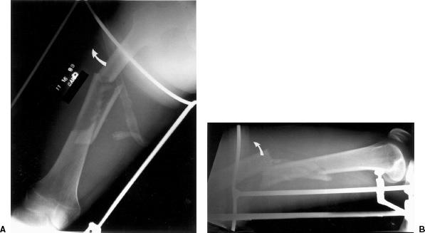
 Figure 5-14 Anteroposterior (AP) (A) and lateral (B) radiographs of a type IV femoral shaft fracture. The proximal fragment is flexed and abducted (curved arrows) by the gluteal muscles, external rotators, and iliopsoas muscle.
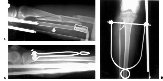
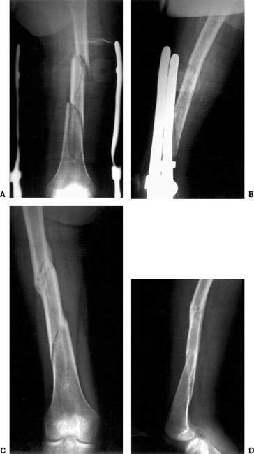
 Figure 5-15 Traction for a Winquist type IV fracture. Lateral radiograph (A) shows a comminuted mid-shaft fracture. Note the high support of the traction device (arrow) is radiolucent throughout most of its length. Anteroposterior (AP) (B) and lateral (C) radiographs show the partially threaded Steinman pin (curver arrow in C) with the treads just entering the cortex. The pin is parallel to the articular surface of the knee to allow uniform traction. The traction pin is held in a Bohler holder.
Fracture management varies with the patient age and presence of other injuries (multiple traumas).
 Traction
Skeletal traction is useful in early treatment when surgery must be delayed due to other injuries and in children from infancy to 10 years of age before application of a spica cast (see definitions in Chapter 2). Traction is the treatment of choice for highly comminuted fractures when fixation or immobilization cannot be achieved. The goal of early traction is to restore length in the first 24 hours. After this period of time hematoma begins to form and organize about the fracture.
Traction is usually accomplished using a K-wire or threaded Steinman pin in the upper tibia (see Fig. 5-15). Steinman pins are larger and may cause more soft tissue damage while K-wires tend to cut through bone over time. Tibial traction is contraindicated with associated ligament injuries to the knee. In this setting, distal femoral traction can be used (see Fig. 5-16). This allows more direct force to be applied to the fracture. Femoral traction may cause scarring in the vastus medialis and lateralis muscles. Calcaneal traction should be avoided due to the high risk of infection.
Types of Traction
Thomas splint
Half ring to hold the traction pin with thigh sling to prevent soft tissue injury and a Pearson attachment (Fig. 5-15) and see Fig. 5-17).
Newfold roller attachment
Steinman pins in plaster to allow early knee motion with traction applied to plaster.
90–90 traction
Both the hip and knee flexed 90 degrees with vertical traction on femur. Used with proximal or subtrochanteric fractures to reduce flexion of the proximal fragment.
Perkins traction
Traction pin in the tibia with traction applied to two pulleys at the end of the bed (~20 lb for adults)
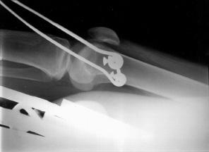
 Figure 5-16 Lateral radiograph demonstrating a traction pin in the distal femur.
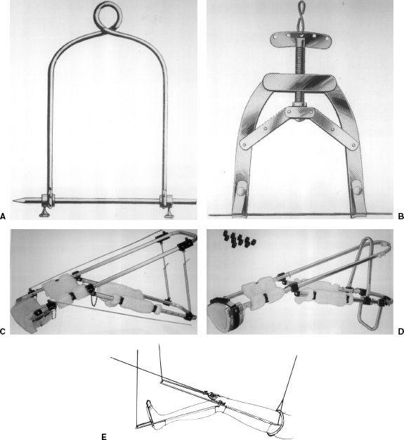
 Figure 5-17 Traction devices. A: Bohler Steinman pin holder with an unthreaded Steinman pin. B: K-wire tractor. C: Brady suspension device for femur and lower extremity fractures. D: Radiolucent Thomas splint with Pearson attachment. E: Illustration of a Thomas splint with Pearson attachment.
Traction Advantages
Early reduction for complex injuries
Alternative to early surgery
Traction Disadvantages
Requires frequent radiographs to check fracture fragment position
Increased incident of nonunion, delayed union (30%), shortening, and malunion
Loss of knee motion
Pin tract infections
Prolonged immobilization and bed rest increases medical complications
SUGGESTED READING
Beaty JH. Operative treatment of femoral shaft fractures in children and adolescents. Clin Orthop. 2005;434:114–122.
Bucholz RW, Jones A. Current concepts review: Fractures of the shaft of the femur. J Bone Joint Surg. 1991;73A:1561–1566.
Buxton RA. The use of Perkins traction in treatment of femoral shaft fractures. J Bone Joint Surg. 1981;63B:362–366.
Whittle AP, Wood GW. Fractures of the lower extremity. In: Canale ST. Campbell’s operative orthopaedics, 10th ed. St. Louis: Mosby; 2003:2669–2724.
Related posts:
Stay updated, free articles. Join our Telegram channel

Full access? Get Clinical Tree


