Fig. 1.1
Piezoelectric effect. Areas of “net” charge within a crystal expand or contract when current is applied to the surface, creating a mechanical wave. When the returning wave strikes the crystal an electrical current is generated
Fig. 1.2
Longitudinal waves are created by the expansion and contraction of piezoelectric crystals within the transducer. These waves are created when an alternating current is applied to the crystals which create compression and rarefaction of molecules in the body
Reflected mechanical sound waves are received by the transducer and converted back into electrical energy via the piezoelectric effect. The electrical energy is interpreted via software within the ultrasound instrument to generate an image which is displayed upon the monitor.
This compression and rarefaction of molecules can be represented graphically as a sine wave (Fig. 1.3) which alternates between a positive and negative deflection from the baseline. The wavelength is the distance between one peak of the wave and the next peak. A cycle is the complete path of the wave. One cycle per second is known as 1 Hz (Hertz). The maximal excursion of the wave in the positive or negative direction from the baseline is the amplitude of the wave. The time it takes for one complete cycle of the wave is known as the period. The amplitude of the wave is a function of the acoustical power used to generate the mechanical compression wave and the medium through which it is transmitted.

Fig. 1.3
Sine wave: when referring to a sine wave a cycle represents the path of the wave from above the baseline then below the baseline and back to the baseline
For most modes of ultrasound, the transducer emits a limited number of wave cycles (usually two to four) called a pulse. The frequency of the two to four wave cycles, called the pulse repetition frequency, is usually less than 2 KHz. The transducer is then “silent” as it awaits the return of the reflected waves from within the body (Fig. 1.4). The transducer serves as a receiver more than 99 % of the time.

Fig. 1.4
The pulsed-wave ultrasound mode depends on an emitted pulse of 2–4 wave cycles followed by a period of “silence” as the transducer awaits the return of the emitted pulse
The pulse repetition frequency (PRF) is the number of pulses being sent out per unit time. By timing the pulse from transmission to reception it is possible to calculate the distance from the transducer to the object reflecting the wave. This is known as ultrasound ranging (Fig. 1.5). This sequence is known as pulsed-wave ultrasound.
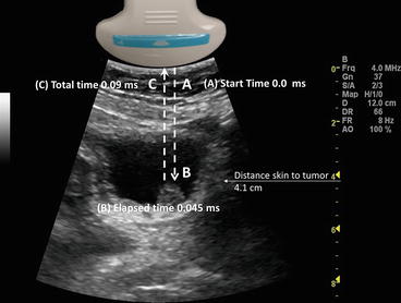
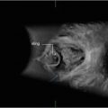
Fig. 1.5
Demonstrates ultrasound ranging. The elapsed time from the transducer (A) to a bladder tumor (B) is 0.045 ms. The total time it takes to travel back to the transducer (C) is 0.09 ms
Ultrasound ranging depends on assumptions about the average velocity of ultrasound in human tissue to locate reflectors in the ultrasound field. The elapsed time from pulse transmission to reception of the same pulse by the transducer allows for determining the location of a reflector in the ultrasound field.
The amplitude of the returning waves determines the brightness of the pixel assigned to the reflector in an ultrasound image. The greater the amplitude of the returning wave the brighter the pixel assigned. Thus, an ultrasound unit produces an “image” by first causing a transducer to emit a series of ultrasound waves at specific frequencies and intervals and then interpreting the returning echoes for duration of transit and amplitude. This “image” is rapidly refreshed on a monitor to give the impression of continuous motion. Frame refresh rates are typically 12–30/s. The sequence of events depicted in Fig. 1.6 is the basis for all “scanned” modes of ultrasound including the familiar gray-scale ultrasound.
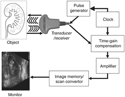
Fig. 1.6
Schematic depiction of the sequence of image production by an ultrasound device
Frequency and wavelength affect the velocity with which sound travels through tissue. The velocity of sound in tissue is constant; therefore, changing the frequency will change the wavelength and influence the depth of penetration.
The velocity with which a sound wave travels through tissue is a product of its frequency and its wavelength. The velocity of sound in a given tissue is constant. Therefore, as the frequency of the sound wave changes the wavelength must also change. The average velocity of sound in human tissues is 1,540 m/s. Wavelength and frequency vary in an inverse relationship. Velocity equals frequency times wavelength. As the frequency diminishes from 10 to 1 MHz the wavelength increases from 0.15 to 1.5 mm. This has important consequences for the choice of transducer depending on the indication for imaging.
Common Ultrasound Interactions with Human Tissue
Ultrasound waves are altered in a variety of ways as they interact with human tissue. There may be loss of energy, change in direction or a change in frequency. In order to maximize image quality and correctly interpret the images the sonographer must understand these interactions.
Attenuation
Sound waves lose energy as they interact with tissue and fluid within the body [2]. This interaction is called attenuation. Attenuation is measured in dB/cm/MHz. The greater is the attenuation, the more energy is lost as the soundwave passes through the tissue. The amount of attenuation that may occur varies by specific tissues. For example, the kidney has an attenuation of 1.0 and muscle an attenuation of 3.3. Therefore, sound waves will lose more energy as they pass through muscle.
The three most important mechanisms of attenuation are absorption, reflection and scattering. Absorption occurs when the mechanical kinetic energy of a sound wave is converted to heat within the tissue. Absorption is dependent on the frequency of the sound wave and the characteristics of the attenuating tissue. Higher frequency waves are more rapidly attenuated by absorption than lower frequency waves.
Correcting for Attenuation
Since sound waves are progressively attenuated with distance traveled, deep structures in the body (for example kidney) are more difficult to image. Compensation for loss of acoustic energy by attenuation can be accomplished by selecting a lower frequency or by increasing the acoustic power. Adjusting the gain settings to increase the sensitivity of the transducer to the returning sound waves and will result in a brighter image, however, it will not increase the effective energy of the reflected ultrasound wave.
Refraction
Refraction occurs when a sound wave encounters an interface between two tissues of differing impedance and at any angle other than 90°. When a wave strikes an interface at an angle a portion of the wave is reflected and a portion is transmitted into the adjacent tissue. The transmitted wave is refracted, which results in a loss of some information because the wave is not completely reflected back to the transducer (Fig. 1.7).
Fig. 1.7
When a wave strikes the interface between two tissues of differing impedance, the wave is usually partially reflected and partially transmitted with refraction. A portion of the wave is reflected (θR) at an angle equal to the angle of insonation (θi), a portion of the wave is transmitted at a refracted (θt) angle into the second tissue
There are also potential errors in registration of object location because of the refraction of the wave.
Correcting for Refraction
Refraction may be minimized by altering the angle of insonation to make it as close to 90° as feasible.
Reflection
Reflection which occurs when a sound wave strikes an object with a large flat surface is called a specular reflection. Specular reflection may occur, for example, when sound waves strike the bladder wall during pelvic ultrasound.
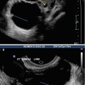
Diffuse reflection occurs when an object is small or irregular resulting in a scattering pattern or “speckle effect”. This type of reflection may often be seen with ultrasound of the uterus or testis (Fig. 1.8).
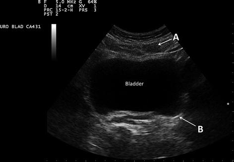
Fig. 1.8
In this transverse image of the bladder, the rectus abdominis muscle (A) is a diffuse reflector. Note the speculated or finely granular nature of the muscle. The bladder wall (B) serves as a specular reflector. A specular reflector reflects sound waves at an angle equal to the incident angle without producing a pattern of interference caused by scattering
Correcting for Reflection
Recognizing reflection as a normal occurrence with ultrasound as opposed to a pathological abnormality of tissue is important. This is a physical property of ultrasound waves and there are no machine settings to correct for reflection. When reflection impedes the interpretation of some portion of the ultrasound field, it can be mitigated by changing the angle of insonation.
Impedance
Impedance occurs when a certain amount of energy is reflected at the interface between tissues of differing tissue density. The amount of energy reflected increases when there is a greater difference between the tissue. For example, there is very little difference in impedance between kidney (1.63) and liver (1.64) so it is difficult to distinguish between these two organs unless there is a layer of fat around the kidney which has a lower impedance factor of 1.38 (Table 1.1).
Table 1.1
Impedance of tissue
Tissue | Density (kg/m3) | Impedance |
|---|---|---|
Air and other gases | 1.2 | 0.0004 |
Fat tissue | 952 | 1.38 |
Water and other clear liquids | 1,000 | 1.48 |
Kidney (average of soft tissue) | 1,060 | 1.63 |
Liver | 1,060 | 1.64 |
Muscle | 1,080 | 1.70 |
Bone and other calcified objects | 1,912 | 7.8 |
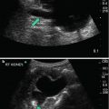
Fat has a sufficient impedance difference from both kidney and liver that the borders of the two organs can be distinguished by virtue of the intervening fat (Fig. 1.9).
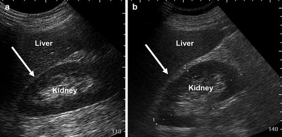
Fig. 1.9
Image (a) demonstrates that when kidney and liver are directly adjacent to each other it is difficult to appreciate the boundary between the capsules of the kidney and liver (arrow). Image (b) demonstrates that when fat, which has significantly lower impedance (arrow) is interposed it is far easier to appreciate the boundary between liver capsule and fat
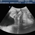
If the impedance differences between tissues are very high, complete reflection of sound waves may occur, resulting in acoustic shadowing (Fig. 1.10).

Fig. 1.10
In the urinary bladder, reflection of sound waves is the result of large impedance differences between urine and the bladder calculus (thin arrow). Acoustic shadowing results from nearly complete reflection of sound waves (area between the thick arrows)
Correcting for Impedance
There are no machine settings to correct for impedance. Imaging the patient from different angles to avoid the interface with large impedance differences may be helpful. In the case of a patient with bladder stones, having the patient physically turn or rotate will cause the stones to move, confirm the presence of the mobile stones and allow imaging of different parts of the bladder.
Common Artifacts
Sound waves are emitted from the ultrasound transducer with a known amplitude, direction, and frequency. However, interactions with tissues in the body result in alterations of these parameters. Because of the physical properties of ultrasound and the assumption by software algorithms in the ultrasound machine that returning sound waves have undergone alterations according to expected physical principles such as attenuation with distance, images are sometimes produced which do not accurately reflect the underlying anatomy. These are known as artifacts. Knowing the most common artifacts in ultrasound and how to correct for them is important when performing and interpreting ultrasound
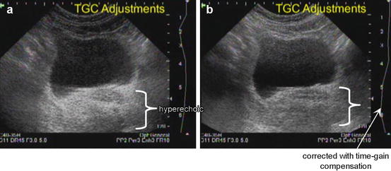
Increased Through-Transmission
When sound waves pass through tissue that has less attenuation than surrounding tissue “increased through-transmission” will result. For example, the area distal to a fluid-filled bladder will appear brighter than surrounding histologically identical tissue. This hyperechogenicity may obscure structures within the area of increased through-transmission (Fig. 1.11).
 Essentials for Setting Up Practice in Clinician Performed Ultrasound
 Practical Application of Ultrasound in the Assessment of Pelvic Organ Prolapse
 Pelvic Ultrasound in the Assessment of Female Voiding Dysfunction
 Machine Settings and Technique of Image Optimization
 Ultrasound Imaging of Gynaecologic Organs
 Principles and Applications of 3D Pelvic Floor Ultrasound


Related posts:
Essentials for Setting Up Practice in Clinician Performed Ultrasound
Practical Application of Ultrasound in the Assessment of Pelvic Organ Prolapse
Pelvic Ultrasound in the Assessment of Female Voiding Dysfunction
Machine Settings and Technique of Image Optimization
Ultrasound Imaging of Gynaecologic Organs
Principles and Applications of 3D Pelvic Floor Ultrasound
Stay updated, free articles. Join our Telegram channel
Full access? Get Clinical Tree
