(1)
Department of Radiology, Winthrop-University Hospital, Mineola, NY, USA
Keywords
Anatomy, thoracic spineBiopsy, diskBiopsy, paraspinal soft tissuesBiopsy, vertebraeThoracic spine biopsy, coaxial techniqueImaging guidance, computed tomographyImaging guidance, fluoroscopyPercutaneous spine biopsy, complicationsPercutaneous spine biopsy, indicationsPercutaneous spine biopsy, contraindicationsSpine biopsy, thoracic spineLearning Objectives
- 1.
To review the radiologic anatomy that is pertinent toward the safe performance of thoracic spine biopsy
- 2.
To review the indications and contraindications for thoracic spine biopsy
- 3.
To learn image-guided percutaneous thoracic spine biopsy approaches and techniques
5.1 Introduction
Image-guided percutaneous thoracic spine biopsies are the second most commonly performed biopsy procedure of the spinal axis, second to lumbar spine biopsies (Rimondi et al. 2008; Heyer et al. 2008). The proximity to the lungs can be a source of major concern for operators who perform this procedure. Fortunately, the presence of consistent osseous landmarks, including the posterior ribs and their articulation with the vertebral body, can be used to avoid injuring the lung. A sound understanding of the radiologic anatomy of the thoracic spine can assist in enhancing the safety margin of this procedure. In general, posterior approaches are required to access the thoracic vertebrae, as the overwhelming majority of lesions are usually located within the vertebral body and/or pedicle, with a lesser proportion of lesions seen within the intervertebral disk and even fewer lesions in a paraspinal soft tissue location. The biopsy needle size and number of passes may be limited depending on the lesion size, extent, and location within the thoracic spine. While this may increase the challenge of the image-guided percutaneous spine biopsy procedure, thoracic spine biopsy is a procedure that is associated with a high diagnostic yield, 92% in one large series (Rimondi et al. 2008). Most thoracic spine biopsies are performed at the mid or lower thoracic spine levels. The majority of thoracic spine biopsies are requested to assess for the possibility of a neoplastic process. The suspected thoracic spine abnormality is often identified on an MRI examination. The increased use of post-treatment imaging surveillance with PET-CT has also resulted in the identification of spine lesions that may require additional evaluation. Whenever possible, these prior studies should be carefully scrutinized to determine if alternative, and possibly safer, biopsy sites within the lumbar spine, sacrum, or pelvis are present. When thoracic spine biopsy is indicated, an understanding of the pertinent radiologic anatomy, the possible approaches to the target lesion, and the available biopsy devices and techniques will increase the efficiency, safety, and success of the image-guided percutaneous thoracic spine biopsy procedure.
5.2 Anatomic Considerations
There are usually 12 rib-bearing thoracic vertebrae. In the presence of a transitional vertebral anatomy at the thoracolumbar junction, 11 or 13 thoracic vertebrae may occasionally be encountered. It is critical that the operator and the diagnostic radiologist be vigilant to the occurrence of these findings when present, in order to prevent the possibility of a wrong-level biopsy. Counting the vertebral bodies starting from the cervical spine can be helpful as there are seven cervical segments (Carrino et al. 2011). Alternatively, the counting scheme for the biopsy procedure should match the numbering scheme on the pre-procedure studies that identify the site and vertebral level of the lesion in question (Fig. 5.1). As occurs in the lumbar spine, the thoracic vertebrae share morphologic features in common from the first thoracic vertebra to the twelfth thoracic vertebra (Fig. 5.2). The major change that occurs within the thoracic spine as the vertebrae are studied from cranial to caudal is that the vertebral bodies get slightly larger within the lower thoracic spine. This also includes the size of the thoracic pedicles; for example, the T12 pedicles are larger than the T1 pedicles. This observation likely reflects the increased biomechanical load that the lower thoracic vertebrae are exposed to. Unlike the lumbar spine, where the pedicles are obliquely angled toward the vertebral body, the thoracic pedicles maintain a relatively tangential orientation toward the vertebral body. This orientation of the thoracic pedicles, as well as their size, must always be taken into account when considering a transpedicular approach for thoracic spine biopsy. Some thoracic spine lesions, therefore, especially lesions within the posterior median aspect of the vertebral body, may not be accessible with a transpedicular approach. The rib articulates with a vertebra at two junctures, posterior at the transverse process or costotransverse articulation and, more anteriorly, at the posterior aspect of the lateral vertebral body or costovertebral junction. Each vertebra consists of the posterior elements which form the neural arch and include the spinous process, lamina, articular facets, transverse process, and pedicles. The pedicles connect the posterior elements to the vertebral body.


Fig. 5.1
Counting and labeling thoracic vertebral levels can be performed with scout MR or CT images or with fluoroscopy. This becomes particularly important when dealing with subtle thoracic lesions or when sampling thoracic disks. T2-weighted sagittal scout image (a) of the cervical and upper thoracic spine; C2 and T1 are labeled and a partial vertebral compression deformity is present at T7 (arrow). T2-weighted sagittal scout image (b) of thoracic and lumbar spine shows the T7 vertebral compression deformity (curved arrow) with marrow edema and three additional mild vertebral compression deformities (arrows) with marrow edema; T12, L5, and S1 (with marrow edema) are labeled
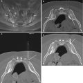
Fig. 5.2
CT anatomy of the thoracic spine. Reformatted midline sagittal CT image (a) shows progressive enlargement of thoracic vertebrae moving in a caudal direction; compare T3 to T12. Axial CT image (b) from contrast enhanced CT study at the T4 level shows the vertebral body (T4), pedicle (p), lamina (L), spinous process (sp) and costovertebral junction (curved arrow). Key anterior structures include the lung, esophagus (E), trachea (T) and aortic arch (Aa). Axial CT image (c) from contrast-enhanced CT study at the T8 level shows the costotransverse (CTr) and costovertebral (CV) articulations. The aorta (A) is well visualized even on bone window algorithm. Note the tangential orientation (dashed line) of the pedicle relative to the vertebral body. Axial CT image (d) from contrast-enhanced CT study at the T12 level shows a more prominent pedicle and a larger vertebral body; the costovertebral articulation is noted (arrow); the transverse process is rudimentary; the aorta (A) is well visualized. Axial CT image (e) from same study in soft tissue algorithm at the T2 level shows the spinal cord (sc) within the spinal canal and the exiting nerve root (curved arrow) within the neural foramen; critical structures at the level of the cervicothoracic junction include the lung apex, the esophagus (E), and the trachea (T); the great vessels lie anterior and lateral to the latter structures
When counting the vertebrae within the spinal axis, the possible presence of a transitional vertebra at the thoracolumbar junction should be considered in order to prevent a wrong-level thoracic spine biopsy procedure.
The critical structures that partially surround the thoracic spine are best understood in the context of their anatomic relations. The posterior elements of the thoracic vertebra are surrounded by the posterior paraspinal musculature which includes the erector spinae muscles. The neural arch, medial pedicle cortex, and posterior vertebral body cortex form the margins of the spinal canal. The spinal canal includes the epidural space, which contains fat and a venous plexus, and the meningeal lined spinal cord which is surrounded by cerebrospinal fluid. Spinal nerves and vascular structures pass through the neural foramina that are located between the pedicles of adjacent vertebral bodies. These vascular structures include branches of the intercostal arteries, some of which provide blood supply to the spinal cord. The lateral relations of the thoracic spinal column include the lungs and pleura. The anterior relations of the spinal column include the posterior mediastinum and mediastinum. The aorta is located anterior and to the left with respect to the vertebral column. The sympathetic plexus lies anteriorly and laterally along the vertebral column. When deciding upon the feasibility of an image-guided percutaneous thoracic spine biopsy procedure, the operator must always factor these critical structures into their approach.
Critical structures at the thoracic spine level |
|---|
Spinal cord |
Lung |
Aorta |
Intercostal vessels |
5.3 Indications
Image-guided percutaneous thoracic spine biopsy is indicated for the evaluation of pathologic lesions that are located within the thoracic vertebrae, intervertebral disks, and/or adjacent paraspinal soft tissues (Table 5.1). The two most common indications for performing thoracic spine biopsy are evaluation of a neoplastic process and spine infection. Neoplastic processes within the thoracic spine are usually secondary lesions associated with metastatic disease, multiple myeloma, or lymphoma. Primary tumors within the thoracic spine, though uncommon, may also require a biopsy procedure. A biopsy may also be required in order to distinguish between a pathologic and an osteoporotic vertebral compression fracture (Figs. 5.3 and 5.4). As with all clinically indicated invasive interventions, the biopsy result should clearly influence the clinical management of the patient. This is the primary benefit of the biopsy procedure. If this benefit will not be achieved with the requested procedure, then it might not be necessary to subject the patient to an invasive procedure. The importance of reviewing all imaging studies prior to considering a thoracic spine biopsy is again emphasized. The remainder of the spinal axis and body should be studied in order to identify other possible sites, for example, within the lumbar spine, sacrum, or pelvis, which can be more safely sampled (Fig. 5.5).


Table 5.1
Indications for image-guided percutaneous thoracic spine biopsy
1. Infection |
Spondylitis-diskitis |
Paraspinal abscess |
2. Neoplastic |
Primary osseous neoplasm |
Evaluation of solitary bone lesion |
Secondary osseous neoplasm |
Osseous metastatic disease or involvement by systemic malignancy |
Diffuse marrow replacement process |
Evaluation of neoplastic lesions with diffusion restriction or FDG-PET avidity post-treatment to assess for treatment response |
Paraspinal soft tissue mass |
Pathologic vertebral body compression fracture |
3. Pretreatment (including the above categories) |
Tissue characterization prior to treatment initiation |
Fig. 5.3
A 65-year-old female with history of breast cancer and back pain. Single posterior projection from a whole body bone scan (a) shows focal radionuclide uptake (arrow) within the mid-thoracic spine. T2-weighted sagittal image (b) shows a partial vertebral compression deformity with marrow edema (arrow) and bone retropulsion into the spinal canal. Focal inferior vertebral endplate edema and disk edema (curved arrow) are seen above the vertebral compression deformity. Reformatted sagittal CT image (c) in bone window algorithm shows a partial vertebral compression deformity (arrow) with loss of the trabecular striations and anterior bone formation. Axial CT image (d) from the bone biopsy procedure shows the tip of a bone needle (arrow) within the predominantly lytic vertebral body lesion; scant tissue was obtained with this needle. Axial CT image (e) shows a soft tissue cutting needle within the lesion. Multiple soft tissue cores confirmed the presence of metastatic breast cancer in this patient with a pathologic vertebral compression fracture
Fig. 5.4
A 77-year-old female with chronic, severe low back pain. Reformatted sagittal CT image (a) in bone window algorithm shows a vertebra plana deformity of the T12 vertebral body (arrow) with small amounts of gas with the anterior vertebral body and adjacent disk space; mild bone retropulsion into the spinal canal is noted as is focal kyphosis. Marked osteopenia is seen. Biplane fluoroscopic images (b) in the frontal and lateral projection show coaxial advancement of a bone biopsy needle into the pedicle (arrow). Lateral fluoroscopic image (c) shows further advancement of the bone needle into the posterior vertebral body (curved arrow); the vertebral endplates (arrows) show the severity of this collapse, which limits advancement of the bone needle. The biopsy samples showed no evidence of malignant cells in this patient with an osteoporotic vertebral compression fracture
Fig. 5.5
A 7-year-old female with back pain (same patient as in Fig. 5.1). T1-weighted sagittal scout image (a) of the thoracic and lumbar spine shows multiple thoracic vertebral compression deformities and hypointense vertebral body marrow signal within the T9 and S1 vertebra (arrows). Axial CT image (b) shows biopsy of the S1 vertebra (arrow); 5 bone cores were submitted to pathology. The biopsy was nondiagnostic
5.4 Contraindications
The major contraindication to performing a thoracic spine biopsy is uncorrected coagulopathy (Table 5.2). Special consideration is also given to patients with neurologic compromise and in whom the imaging findings are consistent with acute spinal cord compression. These patients will require immediate surgical decompression of the spine, and this important intervention should not be delayed by a spine biopsy procedure. As with image-guided percutaneous spine biopsy procedures in the other segments of the spinal axis, thoracic spine biopsy procedures should not be performed on unstable patients. Given the risk of spinal cord or lung injury, the procedure should be avoided in uncooperative patients. As there are 12 thoracic vertebrae, the possibility of occurrence of benign lesions with certain pathognomonic imaging features is not uncommon in the thoracic spine. Bone islands and Schmorl’s nodes may not require a biopsy procedure. For probably benign lesions, it may also be helpful to obtain and review the patient’s prior studies, if available, or clinically correlate the finding and perform follow-up imaging surveillance only if deemed clinically necessary.
Table 5.2
Contraindications to image-guided percutaneous thoracic spine biopsy
Absolute |
Uncorrected coagulopathy |
Acute spinal cord compression |
Untreated infection in patient with suspicious mass lesion |
Relative |
Patient factors |
Combative or uncooperative patient |
Clinically unstable patient |
Lesion type |
Vascular lesion |
Probable benign lesion |
Lesion size |
Discretion must be exercised with smaller lesions (<5 mm in diameter) |
Limited or no specimen yield may result in a false-negative biopsy |
Lesion location |
Defer biopsy for lesions located adjacent to critical structures or inaccessible locations |
5.5 Risks and Complications Associated with Thoracic Spine Biopsy and How to Minimize Them
The risks and complications that are associated with image-guided percutaneous thoracic spine biopsy are similar to those observed with lumbar spine biopsy (Olscamp et al. 1997; Tehranzadeh et al. 2007) (Table 5.3). There are, however, two major differences between thoracic spine biopsy and biopsy in other segments of the spinal axis. First, the risk of pneumothorax takes on a greater priority when performing a thoracic spine biopsy. There is much greater surface area of lung parenchyma at risk in thoracic spine biopsy as compared to cervical or lumbar spine biopsies where the lung apices and bases, respectively, are at risk. Second, the thoracic spinal cord is a structure at risk when performing a thoracic spine biopsy. Careful attention to technique and utilization of the appropriate osseous landmarks whether using CT or fluoroscopic guidance will help to reduce the likelihood of a lung or spinal cord injury. Similarly, the use of coaxial technique, by incurring only one single pass with a guide cannula, will decrease the likelihood of injuring normal anatomic structures. All biopsy instruments can then be passed through the guide cannula multiple times without disturbing the surrounding soft tissue structures. Active monitoring of the location and excursion of these biopsy instruments will also enhance the margin of safety for any biopsy procedure (Fig. 5.6). Procedure-related hemorrhage can be mitigated by adhering to appropriate coagulation status protocols, holding anticoagulant or antiplatelet medications for an appropriate period of time, and using coaxial technique. In the thoracic spine, it is important to be extremely careful navigating needles adjacent to the anterior neural foramina and near the inferior margins of the posterior ribs as these are anatomic locations where normal vascular structures are located. Utilization of standard thoracic biopsy techniques such as the transpedicular, costotransverse, and costovertebral approaches help to reduce the likelihood of injury to these vascular structures.

Table 5.3
Percutaneous thoracic spine biopsy – potential risks and complications
Tissue injury |
Pneumothorax |
Spinal cord injury |
Vascular injury |
Hemorrhage Superficial or subcutaneous Deep – hemorrhage into tumor and/or spinal canal can result in acute neurologic changes or retroperitoneal hemorrhage can result in hypotension or severe pain |
Infection (superficial or deep) in those cases being performed to assess for neoplasm |
Inappropriate needle placement Breach of the anterior vertebral body or medial pedicle cortex Needle placement within the spinal canal Wrong level |
Inadequate tissue sampling |
Technical failure – biopsy system failure, lost specimen |
Tumor seeding along the biopsy tract |
Radiation exposure |
Anesthesia complications Aspiration, airway compromise, respiratory depression |
Fig. 5.6
A 7-year-old female with back pain, 1 month later. Axial CT image (a) from a T9 biopsy procedure shows advancement of a bone needle via a costotransverse approach (arrow). Axial CT image (b) shows needle tip at lateral margin of vertebral body (arrow); because of the steep nature of this approach, the needle tip points at the vertebral body, not the lung. Axial CT image (c) shows entry of the bone needle (curved arrow) into the posterior vertebral body. The beam hardening artifact distal to the needle provides a good estimate of the needle trajectory within the remainder of the vertebral body (dashed lines); the needle trajectory was adjusted at the point of insertion within the lateral vertebral cortex (compare to image b). A reformatted sagittal image obtained with CT fluoroscopy (d) shows the needle tip’s (curved arrow) relationship to the vertebral endplates and anterior vertebral cortex. Axial CT image (e) shows coaxial advancement of the bone needle (arrow) through the guide cannula (curved arrow) in order to obtain additional bone cores (a total of 6 bone cores). Compare this final trajectory with that estimated in Figure c. Subsequent histopathologic analysis showed Langerhans cell histiocytosis
5.6 Imaging Guidance
CT and fluoroscopy are the two modalities that are used to perform image-guided percutaneous thoracic spine biopsy (Lis et al. 2004; Ortiz et al. 2010). The key osseous landmarks for imaging guidance are visualized with both modalities. CT does provide additional soft tissue resolution to identify, with better detail, the critical structures in the thoracic spine. In general, many operators tend to use fluoroscopic guidance for transpedicular approaches in the thoracic spine, especially when attempting to sample large or diffuse lesions within the thoracic vertebral body (Fig. 5.7) (Pierot and Boulin 1999). More experienced operators will also use fluoroscopy to perform percutaneous disk biopsies utilizing a posterior oblique approach that keeps the needle between the medial aspect of the rib and the lateral aspect of the pedicle. The ability of CT to visualize the lesion and its relation to the vertebra and to nearby critical structures tends to make CT the preferred modality for image-guided percutaneous thoracic spine biopsy. It is particularly helpful in sampling the posterior elements and the paraspinal soft tissues (Fig. 5.8). CT fluoroscopy increases the efficiency of the procedure by allowing faster monitoring of needle advancement and position. Since both CT and fluoroscopic guidance entail radiation exposure, adherence to sound radiologic imaging and shielding principles will assist in limiting radiation exposure not only to the patient but also to the operator and the operator’s staff.