Chapter 6 Transducers
INTRODUCTION
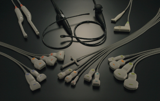
The transducer is one of the most critical components of any diagnostic ultrasound system. There are many types of ultrasound transducers that can be selected before performing an ultrasound investigation as seen in Figure 6.1, and a great deal of attention should be paid to selecting the most appropriate transducer for the application.
Ultrasound transducers are described by their type and operating frequency which can range from 2 MHz up to 20 MHz and are selected based on their ‘fitness for purpose’. The end user must recognize that different applications require an appropriately selected transducer which is best suited for a particular investigation.
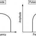
We need to be aware that there is a trade-off between image resolution and the penetrating depth of ultrasound which is governed by its frequency. For example, a 12 MHz transducer has very good resolution, but cannot penetrate very deep into the body compared to a 3 MHz transducer which can penetrate deep into the body, but the resolution is not as good as the transducer operating at 12 MHz. In general use, the highest frequency transducer which will reach the required depth should always be employed.
THE TRANSDUCER
Diagnostic transducers act as both a transmitter and receiver of ultrasound and are able to produce beams which can be directed in various ways to improve the quality of the images that we see on screen.
The primary component of the transducer is made from a piezoelectric material which means they are able to convert one form of energy to another, in this case electrical energy into mechanical energy and vice versa.
Components and Construction of a Typical Transducer
There are many types of transducers ranging from a simple single element to electronic multi-array probes which have hundreds of elements. The components and construction of these different types of transducers are principally the same. To understand how modern day electronic multi-element transducers function we need to start by considering the construction and components of a simple single element circular transducer. This is illustrated in Figure 6.2.
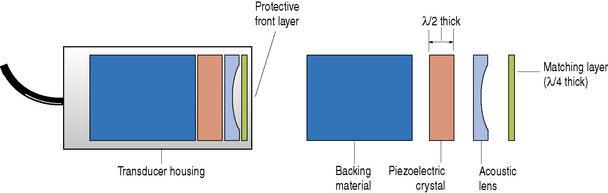
The main components of a typical ultrasound transducer consist of:
Physical housing
This contains all the individual components including the crystal, electrodes, matching layer, and backing material. This housing provides the necessary structural support and acts as an electrical and acoustic insulator.
Electrical connections
Two electrical connections are formed on the front and back face of the crystal by plating a thin film of gold or silver on these surfaces. These electrodes are connected to the ultrasound machine which generates the short burst of electrical pulses to excite the crystal and through the piezoelectric effect generates a pulse of ultrasound energy.
Piezoelectric element
Transducers operate on the piezoelectric effect which was discovered by Jacques and Pierre Curie in 1880. They found that certain crystalline minerals when subjected to a mechanical force became electrically polarized which means that they generated voltages. They also discovered that the converse was true, i.e. if a short electrical burst was applied to these crystals it would cause them to vibrate. The term ‘piezoelectric’ was derived from the Greek word ‘piezein’, meaning to press or squeeze.
By utilizing this piezoelectric property an ultrasound transducer can act both as a transmitter and receiver of ultrasound.
In transmission mode, a short burst of electric energy generated by the ultrasound scanner (typically one to three cycles of alternating voltage for imaging) is sent to the transducer generating an ultrasound pulse of energy. Reflected ultrasound echoes returning to the transducer face are detected, causing mechanical vibrations which are converted into electrical voltages. It is these electrical signals that are processed by the ultrasound machine which form the images that we see.
What are they made of?
Quartz is a naturally occurring material with piezoelectric properties and was extensively used in the development of early machines. This has now been superseded by man-made ceramics such as lead zirconate titanate (PZT) which are more efficient, have better sensitivity, and can easily be shaped.
How do you determine a transducer’s operating frequency?
The operating frequency of a transducer is critically governed by the thickness of the piezoelectric crystal. For maximum efficiency the crystal should be operating at its ‘natural’ or ‘resonant’ frequency. This occurs when the thickness of the crystal corresponds to half a wavelength (λ/2).
We have already discovered that wavelength and frequency are inversely related, i.e. as wavelength decreases frequency increases, therefore we can appreciate that thinner piezoelectric materials produce higher resonant frequencies. Typical diagnostic ultrasound elements are between 0.2 mm and 1 mm thick.
A transducer operating at a resonant frequency of 2 MHz would have a thickness around 1 mm. In comparison, a transducer operating at a much higher frequency, say 7.5 MHz, would have a typical thickness of 0.3 mm.
Purpose of the backing material
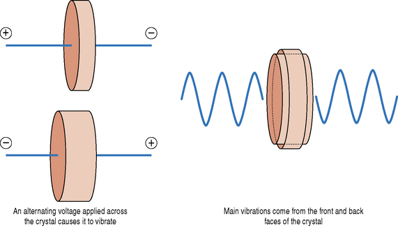
Let us consider a simple single element transducer as illustrated in Figure 6.3. When a short burst or pulse of electricity is applied to a crystal it causes it to vibrate in all directions. The main vibrations come from the front and back faces of the piezoelectric crystal. We are only interested in the vibrations that come off the front face of the transducer. To try and eliminate the vibrations from the back face, and to control the length of vibrations from the front face, a backing or damping material is used. This damping material, which typically consists of tungsten powder and plastic or epoxy resin, is attached to the back face of the piezoelectric crystal.

Fig. 6.3 When a short pulse of electricity is applied across the crystal it causes it to vibrate. The main vibrations are generated from the front and back face of the crystal

Stay updated, free articles. Join our Telegram channel

Full access? Get Clinical Tree

