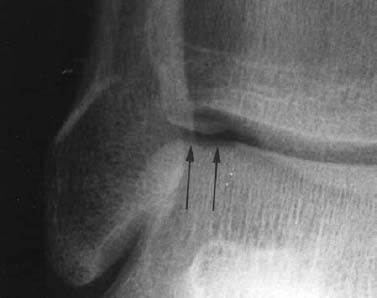
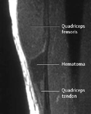
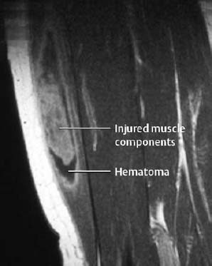
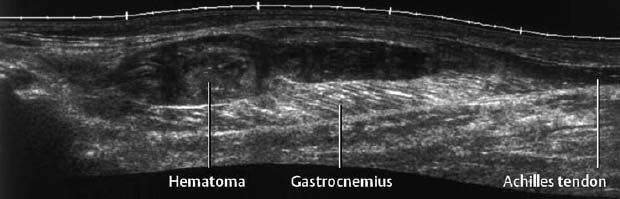
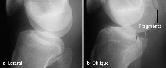
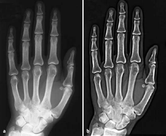
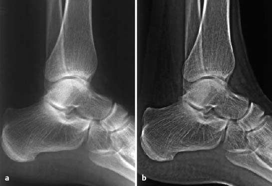
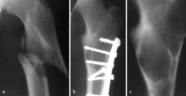
1 Trauma In the broadest sense of its meaning, traumatology can be described as the medical specialty that studies damage to the human body, especially to the cell. The traumatic agent can be physical (e.g., mechanical trauma, temperature changes, radiation), chemical, or biologic (e.g., bacteria, viruses, etc.). Regardless of the etiology, the body can be expected to exhibit two effects: a local effect at the site of the trauma, and a systemic effect on the body (e.g., shock, fever, and others). In a narrower sense, traumatology deals with mechanically induced injuries of the musculoskeletal tissue. For practical reasons, other physical etiologies, such as thermal injuries, are included in this chapter. A fracture is a break in the continuity of bone. Where the bone is not completely separated, a break is called a fissure. Etiologically, fractures can be classified as direct fractures (a fracture at the site of the causative force, Fig. 1.1) or indirect fractures (a fracture at a site remote from the causative force). Furthermore, the degree and extent of the injury differentiate complete from incomplete fractures. Typical incomplete fractures are greenstick fractures, buckle fractures, and fissures. Joint injury refers to any damage to the capsuloligamentous system, cartilaginous structures, and osseous articular surfaces following contusions, subluxations, and dislocations. Since the ligaments that connect the joints are more or less incorporated in the joint capsule, the term ‘capsuloligamentous injury’ is frequently used. Such an injury can be an elastic strain, a plastic sprain, or a complete rupture. Joint injuries of particular interest are fractures and avulsions of cartilage (chondral fractures) with or without attached osseous fragments (osteochondral fractures, ‘flake fractures’, Fig. 1.2). Subluxation and dislocation result from forcefully displaced articular surfaces that have failed to return to their normal position. Muscles can suffer closed or open tears and crush injuries. Furthermore, indirect injuries can cause elastic strains, plastic sprains, or tears (Figs. 1.3–1.5). Direct mechanical trauma (e.g., lacerations) and indirect trauma that triggers maximum muscular contraction can tear a tendon. The tear frequently occurs where the tendon shows signs of degeneration. Roentgen’s discovery of X-rays at the end of the 19th century not only revolutionized the diagnostic evaluation of trauma, but also transformed the treatment of injuries to the skeleton, joints, and soft tissues. The dominant role of conventional radiology now must be reassessed at increasingly shorter intervals in view of the continuing emergence of new imaging modalities. Some of the recently introduced techniques use X-rays, such as digital radiography or CT, while others are based on completely different physical principles, such as sonography or MRI. Fig. 1.2 Joint injury. Osteochondral fracture of the lateral talus. Fig. 1.3 Tendon injury. Acute hematoma at the transition of the quadriceps femoris muscle with the quadriceps tendon on sagittal T1-weighted spin echo image. Fig. 1.4 Tendon injury. Large subacute hematoma in the femoris muscle on enhanced T1-weighted spin echo image. Fig. 1.5 Sonographic visualization of a muscle injury. Large hematoma in the gastrocnemius muscle secondary to torn muscle fibers. The tear itself is not discernible. Radiographs in two projections perpendicular to each other, preceded only by the clinical assessment, are generally the first and often the only diagnostic images needed for the evaluation of trauma. Some fractures, such as fractures of the radial head or femoral condyles, are only visible on additional oblique views (Fig. 1.6). Special views designed to eliminate superimposed structures are used to display complicated anatomic structures such as those encountered in the facial and carpal bones, in the shoulder and hip joint, and in the mid foot. In general, conventional radiography promptly diagnoses fractures and provides relevant information as to whether the adjacent joint is involved and how the fracture fragments are positioned. Conventional radiographs can almost always be obtained under the difficult circumstances encountered in the acute setting of severe trauma. Even with the availability of more advanced methods, such as MRI, surgical planning is still guided primarily by the clinical and radiographic findings. Following internal or external fixation with reduction of dislocations and alignment of displaced fracture fragments, radiographs are mandatory to confirm the results of these therapeutic measures. Radiographs, however, cannot always monitor the progress of healing adequately. Complications of the healing process, such as infections, reflex osteodystrophy or inadequate internal fixation, are still diagnosed clinically, and radiographs are only confirmative. Radiographs play a limited role in skeletal regions that have complex anatomy or are superimposed by soft tissues and bowel loops, and in the evaluation of soft-tissue injuries. On the other hand, radiographically demonstrated soft-tissue changes can be used as indirect signs of osseous pathology. Diagnostic imaging and image-guided therapy are inconceivable today without digital manipulation. Computed tomography (CT), digital subtraction angiography (DSA), and magnetic resonance imaging (MRI) rely on digital image acquisition and processing. Two digital methods are used for projection radiography today: digital image enhancement and digital luminescence radiography. Both methods store the intensity distribution of the transmitted X-rays as a set of binary data, instead of analog data as with the film-screen system. Digital enhancement radiography is a fluoroscopic method that can be implemented as digital cardiography, digital subtraction angiography, and digital spot films. Their numerous advantages have led to the acceptance of digital methods in diagnostic and therapeutic cardiology and angiography. Because of digital enhancement radiography’s limited spatial resolution, it is rarely used as a substitute for X-rays, except for intra- and postoperative assessment of the position of fracture fragments. Currently, digital luminescence radiography or storage phosphor radiography is the most commonly used digital method for obtaining radiographs (Figs. 1.7, 1.8), using the established projections of the film-screen technique. It can also be used with existing conventional tomographic equipment. The conventional film-screen cassette is replaced with a reusable storage phosphor imaging plate which captures the incoming X-rays as a latent image. The reader scans the plate with a laser beam and releases the stored energy as light. This stimulated light emission is measured by a photo-multiplier tube interfaced to the image processor. The quality of digital luminescence radiography is adequate for diagnosing traumatic changes in all parts of the skeleton. The inferior spatial resolution of digital luminescence radiography is compensated for by its superior contrast resolution, i.e., the superior detection of small contrast differences. The linear response curve (gradient type) of the storage phosphor and the capability of display processing give this method a high tolerance for variations in exposure, reducing the number of films that have to be repeated because of inadequate exposure and ultimately decreasing the radiation dose to the patient. Radiography of the bones and joints with flat panel detectors, an emerging new technique, is still work in progress. CT generates images without superimposed structures, usually along the axial plane. While the patient is in a resting supine position, even anatomically difficult body regions can readily be evaluated noninvasively. A single section can be imaged in seconds and, with the addition of spiral technique (see below), an entire body region obtained during a single breath-hold. CT provides information about the bones and soft tissues and, while the resolution is slightly inferior compared to conventional radiography, is fully adequate to evaluate skeletal trauma. CT may often show post-traumatic changes not shown by radiography (Fig. 1.9). The established indications of CT in trauma are summarized in Table 1.1. It has been reported that up to 18% of fractures not seen on conventional radiographs may be detected by CT in the occipitocervical transition when CT is routinely performed on severely injured patients. Fig. 1.7 Different displays of a digital radiograph with: a contrast scaling adjusted to that of a normal radiograph, b frequency processing with edge enhancement. Fig. 1.8 Further examples of various displays of digital images: a contrast scaling adjusted to that of a normal radiograph, b edge enhancement. Spiral CT acquires a three-dimensional data set by continuous rotation of the X-ray tube around the moving examination table. The selected parameters for section thickness and table motion determine the volume of the body region and the resultant spatial resolution. From the three-dimensional data set, axial images are reconstructed as needed to address the clinical questions. Furthermore, the three-dimensional data set can be used to reformat images in other planes (2-D technique) and to render volume images (3-D technique) (Fig. 1.10). The tremendous improvements in processing speed over the last few years have made volume rendering feasible in daily clinical work. Reconstruction of isotropic voxels generated by the new generation of multi slice spiral CTs also has improved 3-D volume imaging. The 2-D reformatting of sagittal and coronal images from axial images can highlight longitudinal fracture lines and can make it easier to evaluate horizontal interfaces, such as the acetabular roof or orbital floor (Fig. 1.10a). The 3-D rendering allows different displays of the volume data. Surface rendering by thresholding is the most widely used technique. The relatively rapid surface-rendering algorithms dismiss attenuation values below the user-selected threshold of bone attenuation. The soft tissues are computationally removed and the surface of the underlying osseous structure is displayed (Fig. 1.11). The surface rendering for the display of bone has the drawback of including other high-attenuation structures, such as atheromatous plaques, contrast agents, and internal fixation devices. The osseous structures depicted can be manipulated by semiautomatic subtraction of superimposed and potentially interfering anatomic structures. For instance, acetabular fractures can be displayed without the femoral head, or calcaneal fractures without the talus, essentially enacting an ‘electronic disarticulation’. By adding a virtual light source, a shaded surface display (SSD) can be achieved, which enhances the 3-D understanding of the image. Volume rendering requires more computer manipulation. It classifies each voxel of the volume data set and incorporates it into the displayed image. It can provide a transparent 3-D display of any apparent surface from any point of view and allows the comprehensive visualization of fractures. Powerful computers are required to achieve volume rendering at a reasonable speed in clinical applications. All reconstruction methods offer a more effective display of complex anatomic and pathologic structures. Three-dimensional imaging improves the assessment of fractures. Location and extent of the fracture, shape and position of the fracture fragments and the condition of articular surfaces can be better appreciated, making it easier to assess comminuted fractures. Surface rendering, which, in contrast to volume rendering, incorporates only a portion of the data into the 3-D image, provides an inadequate display of undisplaced and intra-articular fragments and fails to show any soft-tissue changes. In comparison to sectional imaging, surface rendering does not increase the detection rate of fractures and should only be supplementary to plain films and axial CT sections in the evaluation of comminuted fractures. The role of arthrography has declined because of the excellent visualization of the intra-articular structures by MRI. However, arthrography still has a role for certain clinical questions, such as adhesive capsulitis, and is still considered to be the ‘gold standard’ for the evaluation of ligamentous injuries of the hand (Fig. 1.12). Moreover, arthrography remains part of CT- or MRI-arthrography and is superior to imaging without intra-articular contrast medium for the evaluation of shoulder instability because of the detailed arthrographic visualization of anatomic structures and pathologic changes. This feature is especially helpful for conditions involving the glenoid labrum and joint capsule.
Definitions
Fracture
Joint Injury
Muscle Injury
Tendon Injury
Role of Imaging in Trauma to the Musculoskeletal System

Conventional Radiology
Digital Radiology
Computed Tomography
Spiral CT, 2-D and 3-D Reconstruction
Arthrography
| Indication | Clinical question |
|---|---|
| Facial bone injuries | Exact determination of the fracture sites and position of the fracture fragments |
| Vertebral injuries | Stability, intraspinal fragment, paravertebral/intraspinal hemorrhage, traumatic disk extrusion, fractures of the occipitocervical transition |
| Pelvic and hip fractures | Fractures of the posterior pelvic ring, acetabular fracture, intra-articular fragment, degree and type of fragment displacement |
| Wrist injuries | Unclear extent of trauma, radioulnar/carpal dislocation, rotational deformity |
| Calcaneal fractures | Fragment displacement, articular involvement |
| Biometric views | Determination of malrotation, length discrepancy, angulation (antetorsion angle of the femoral neck) |
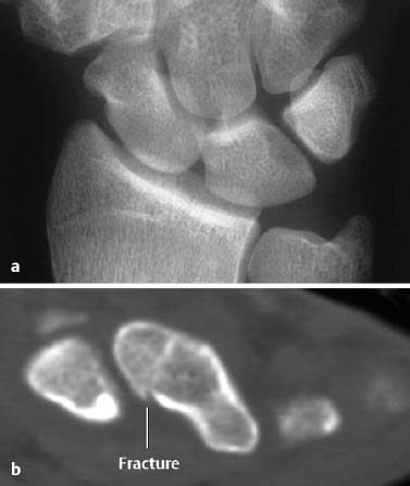
Fig. 1.9 Scaphoid fracture. a The AP radiograph is normal. b The fracture line is clearly delineated by CT.
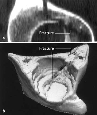
Fig. 1.10 2-D (a) and 3-D (b) reconstruction of an acetabular fracture. The 3-D reconstruction displays the joint as seen from the patient’s feet.
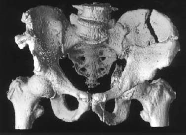
Fig. 1.11 3-D visualization of fractures of left iliac wing and acetabulum.
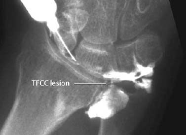
Fig. 1.12 Arthrography showing a tear of the triangular fibrocartilage complex (TFCC).
Sonography
Sonography is beginning to play an increasingly important role in trauma. Among its advantages are availability, low cost, patient acceptance, and lack of radiation exposure. Its disadvantages are operator dependence, long examination times, selective and often incomprehensible documentation, and the inability to penetrate osseous structures. Reasonable indications for sonography in trauma are outlined in Table 1.2. Ruptures of the Achilles and patellar tendons can be diagnosed instantly with great accuracy. Sonography cannot always differentiate between partial and complete rotator cuff tear, and MRI must be added in these cases.
Intrafascial hematomas in the musculature of the extremities can be visualized by sonography and, if necessary, drained under sonographic guidance. Sonography should also be the primary method for evaluation of a suspected sternal fracture. Sternal fractures, which have become a frequent seat belt injury, are seen as breaks in the normal contour of bone surrounded by a hematoma, with inducible relative motion of the fracture fragments (Fig. 1.13). Radiographic visualization of sternal fractures is often inadequate because of superimposed ribs and soft tissues and inherent low bone contrast. Finally, sonography can be superior to radiography in demonstrating rib fractures.
Magnetic Resonance Imaging
MRI can effectively visualize traumatic changes of the skeleton and peripheral soft tissues, such as intramuscular hematomas and ligamentous tears. Initially, the prevailing opinion was that the signal void of cortical bone would preclude the evaluation of skeletal injuries, but this theory has been disproved. In fact, the opposite is true; the lack of any signal from cortical bone augments the signal from adjacent tissues. In particular, visualization of bone marrow has opened entirely new perspectives (Table 1.3).
Stress and insufficiency fractures can present as radiographically unexplained pain. If radiographic changes are present, they might be mistaken for neoplasms or infection, particularly in the absence of periosteal reaction. A space-occupying process can be excluded invariably by MRI. These advantages of MRI are most valuable for evaluating skeletal regions with a complex internal architecture.
Before the availability of MRI, radiologically occult fractures often posed a diagnostic dilemma. MRI can detect not only these fractures, but also other conditions, such as osteonecrosis, degenerative subchondral cysts, and metastases, which might be the cause of the patient’s symptoms (Fig. 1.16).
MRI has its major impact on diagnosing traumatic joint injury. Traumatic injury to the joints was once the domain of arthroscopy, but this has now changed with the introduction of MRI and has led to a better understanding of the immediate and delayed effects of trauma on the joints. Although hyaline cartilage, subchondral lamellar and trabecular bone can be considered separately, they are now increasingly seen as a functional unit. The most frequently encountered and characteristic constellation is the subchondral trabecular fracture with underlying marrow edema. The therapeutic ramification of the bone marrow edema, the so-called ‘bone bruise’, is still not fully understood.
Because of its complex anatomy, the wrist was one of the first anatomic regions to be investigated by MRI, and special surface coils allow high-resolution visualization of the carpal bones. For imaging with conventional MRI, patients must place their hands over their heads, putting them in a relatively uncomfortable position that is rarely tolerated for examination times exceeding 20 minutes. This has been overcome by open MRI systems, which allow the patient to sit outside the unit. The inferior spatial resolution of the open systems, however, can be a problem for those clinical questions that require the evaluation of the triangular fibrocartilage complex or ligaments. Established MRI indications in the wrist include the search for occult fractures of the carpal bones as well as the assessment of osteonecroses, especially of the navicular and lunate. Numerous publications have addressed the role of MRI in the evaluation of injuries of the triangular fibrocartilage complex (TFCC). Like arthrography, MRI visualizes a variety of changes in the TFCC in asymptomatic patients, and it is difficult to determine whether the particular change seen after trauma is traumatic or degenerative in origin.
The evaluation of knee pain undiagnosed by physical examination in the patient with normal radiographs has become the domain of MRI. This technique can demonstrate intraosseous microfractures and has increased our understanding of post-traumatic pain. These trabecular fractures, which are radiographically occult but often scintigraphically positive, can be clearly identified by location and configuration of the abnormal signal pattern. These otherwise unidentifiable microfractures must be considered the most frequent cause of acute post-traumatic pain. Generally MRI findings resolve within 5 to 15 days, although no satisfactory prospective studies have been reported.
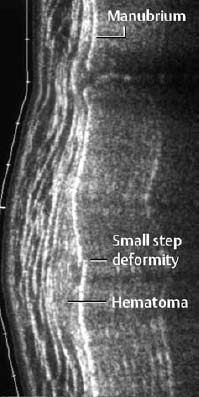
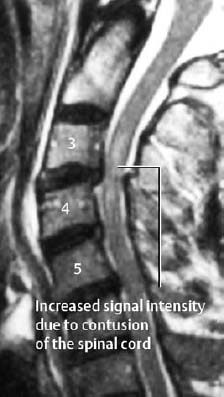
Fig. 1.14 Contusion of the spinal cord and posterior subluxation of C3 on C4 in a trauma patient with neurologic findings (T2-weighted SE images).
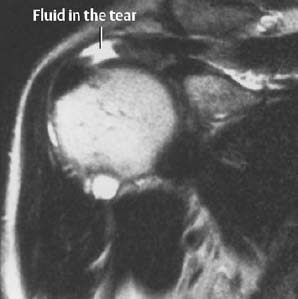
Fig. 1.15 Full-thickness tear of the supraspinatus tendon on T2-weighted SE image.
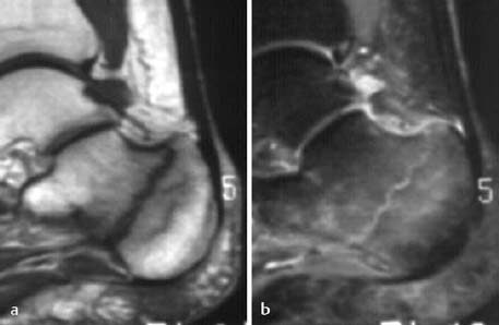
Fig. 1.16 Occult calcaneal fracture with associated bone marrow edema following minor trauma 6 weeks previously and with persistent pain. The radiograph was normal. a T1-weighted SE sequence showing the fracture line as low signal intensity, b STIR sequence showing the fracture line as high signal intensity surrounded by bone marrow edema.
| Body region | Indications |
|---|---|
| Shoulder | Rotator cuff tear, biceps tendon tear and dislocation, Hill-Sachs lesion, avulsion fracture, joint effusion, AC joint separation |
| Elbow, hand, foot | Achilles tendon tear, joint effusion, rupture of the distal triceps and biceps tendon, avulsion fracture |
| Hip | Joint effusion, avulsion fracture, slipped capital femoral epiphysis (epiphyseolysis of the femoral head) |
| Knee | Rupture of quadriceps and patellar tendons, rupture of collateral ligament, joint effusion, Baker cyst |
| Soft tissues | Muscle tear, hematoma, foreign body |
| Ribs, sternum | Radiographically occult fractures |
Complete tears of the anterior cruciate ligament (ACL) are detected with an average accuracy of 90%. Partial tears or distortions of the anterior cruciate ligament, which are characterized by partially intact fibers and severe intra- and periligamentous edema, are not always distinguishable from complete tears. Injuries of the posterior cruciate ligament are less common than ACL tears but are easily detected by MRI.
Even after numerous technical refinements, evaluation of the hyaline cartilage by MRI remains inferior to direct visualization by arthroscopy. This superiority of arthroscopy applies only to chondromalacia and superficial lesions of questionable therapeutic relevance. However, in many instances, osteochondral injuries are easily identified by MRI as the cause of hemarthrosis.
MRI is the most sensitive imaging test for identifying lesions of the rotator cuff of the shoulder joint (Fig. 1.15). Evaluating shoulder instability by MRI remains a controversial issue, as CT-arthrography represents a competing imaging method for this indication. But MRI-arthrography, analogous to CT-arthrography, can be viewed as the ‘gold standard’ for evaluating complex labrocapsular and ligamentous anatomy and pathology. MRI-arthrography can visualize anterior, posterior, or inferior labral injuries and Hill-Sachs defects, as well as injuries of the superior labral-biceps tendon junction.
Scintigraphy
Bone scans are performed with Tc 99 m–labeled diphosphonate and can be obtained as a static study or a dynamic study using the three-phase technique. Other scintigraphic techniques, such as minor Tc 99 m–labeled white blood cell scans, or Tc 99 m–labeled monoclonal antibody scans do not play a significant role in the evaluation of trauma.
Bone scans are established for the detection of radiologically occult fractures, but MRI has replaced this technique in most centers.
The bone scan is well suited for surveying the patient with multiple trauma for the extent of skeletal involvement. It should be kept in mind that reparative changes in juxta-articular appendicular bone might be visible only after the third day. In the diaphyses of the long bones and in the central skeleton, the bone scan might even become positive as late as one week after the trauma. Because of the known low specificity of increased bone activity on bone scan, a positive finding should be correlated with the radiographs.
In pediatrics, bone scanning plays a major role in screening for battered child syndrome (see pp. 132 ff).
Another indication for bone scanning is the search for stress fractures, including stress-induced spondylolysis of the lower lumbar spine. Focally increased osseous activity is often seen well before radiographic changes are detected.
Stress fractures should be differentiated from traumatic or degenerative irritation of tendon insertions (enthesopathy) and traumatic periosteal reaction along diaphyseal bone. Periosteal reaction along the tibia is referred to as ‘shin splints’. In comparison to stress fractures, shin splints show no increased blood flow on the blood pool images.
Post-traumatic complications of the healing process, such as pseudarthrosis and reflex osteodystrophy, can also be demonstrated by bone scanning.
Practical Suggestions for Imaging in the Trauma Setting
- Any traumatized bone must be visualized in at least two projections. It is difficult to meet this requirement for certain anatomic locations, such as the hip or shoulder. Special projections have been proposed for these anatomic regions. (Refer to other texts dedicated to radiographic positioning.)
- For any fracture visualized next to a joint, any articular extension must be searched for. Special views must often be added to the two standard views. If conventional imaging is inconclusive, MRI should be considered.
- If one of two parallel long bones (such as the ulna and radius or the tibia and fibula) is fractured, a fracture of the companion bone must be excluded.
- Any long bone must be visualized in its entire length. In other words, the proximal and distal joint bearing ends have to be included.
- In patients with multiple fractures, subtle findings may be missed if other major injuries are present. A second look at a less busy time or a second reading can be beneficial in detecting findings which might be overlooked. This is particularly applicable to films of patients with multiple trauma.
- Whenever possible, the referring physician should state the traumatic forces and the expected pattern of the traumatic changes. This allows a focused search with the expected injuries kept in mind.
Example: The supination-adduction trauma to the ankle causes a transverse fracture of the lateral malleolus below the syndesmosis, or a rupture of the lateral collateral ligament. Furthermore, this can lead to a vertical osteochondral fracture of the medial talar articulating surface. An awareness of the mechanism of injury will help direct the search pattern. This follows the adage ‘you will find what you look for’.
- It is mandatory to correlate clinical and radiological findings. If no exact or reliable clinical information is supplied, the radiologist or technologist must obtain it directly from the patient.
- While many direct signs of fracture are easily appreciated, indirect signs such as soft-tissue changes are often overlooked. It is important for all images to include indirect signs in the diagnostic process (refer to special traumatology).
- Equivocal radiographic findings should be further evaluated by additional views in other projections, such as oblique views. Other imaging modalities, such as sonography and CT, should be incorporated early in the diagnostic process.
- Fracture lines are not invariably radiolucent. They can be radiodense if fracture fragments
a) overlap,
b) are impacted,
c) are rotated relative to each other, with the radiodense line often sharply delineated, in contrast to a) and b).
| Indications | Clinical question |
|---|---|
| Skeletal trauma | Trabecular fractures, occult fractures, stress fractures, vertebral fractures, suspected spinal cord involvement, posttraumatic osteonecroses, post-traumatic chronic osteomyelitis |
| Joint trauma | Osteochondral fractures, intra-articular ligamentous lesions (cruciate ligaments, collateral ligaments), meniscus injuries (especially in the knee) |
| Trauma of the peripheral soft tissues | Tendon and muscle injuries (hematoma, rupture, ligamentous injury [e.g., shoulder]), tendosynovitis in chronic repetitive microtrauma |
Fracture Classifications and Types
Classification of fractures by their causative mechanisms:
- Traumatic Fractures
These fractures are caused by excessive mechanical loading, which can be sustained by deforming forces that act directly on bone such as tapping, crushing, or penetration, or indirectly from a distance, as occurs with traction, angulation, shearing, or compression. If the loading of bone exceeds a certain point, the bone will fail and fracture.
- Stress and Insufficiency Fractures
Stress fractures are caused by fatigue failure of otherwise normal bone induced by repeated or cyclical stresses. Insufficiency fractures are caused by normal forces or microtrauma and occur in bones of reduced internal strength, such those bones weakened by osteoporosis.
- Pathologic Fractures
These fractures occur in bone weakened by a preexisting condition and are caused by a force that would not break normal bone. They can be considered a local manifestation of an insufficiency fracture. The most common preexisting conditions are bone cysts, osteolytic metastases, and plasmocytoma.
Fracture Types
The morphology of the fracture reflects the direction and level of the traumatic forces. A practical classification of fracture types is illustrated in Fig. 1.20.
A special type of fracture is the compression fracture of the spine (Fig. 1.17).
The classification can be slightly modified by determining whether the fracture is associated with a dislocation (Fig. 1.18), or whether the fracture lines extend to the articular surface (Fig. 1.19).
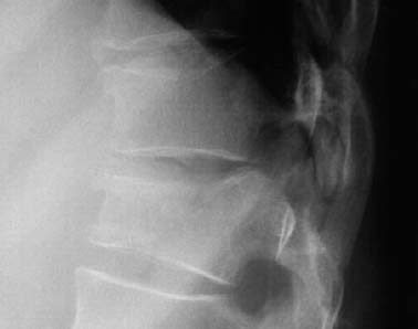
Fig. 1.17 Compression fracture of the T9 and T10 vertebral bodies. There is increased density in the impacted anterior components of the vertebral bodies.
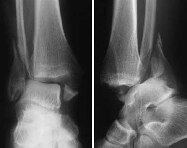
Fig. 1.18 Bimalleolar fracture-dislocation of the ankle. Only the lateral view shows the full extent of the injury.
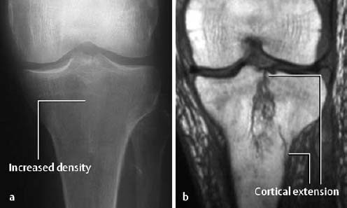
Fig. 1.19 Longitudinal fracture of the tibial plateau seen as indistinct increased density on the conventional radiograph (a). MRI (T1-weighted SE sequence) shows the full extent of the fracture and the cortical involvement (b).
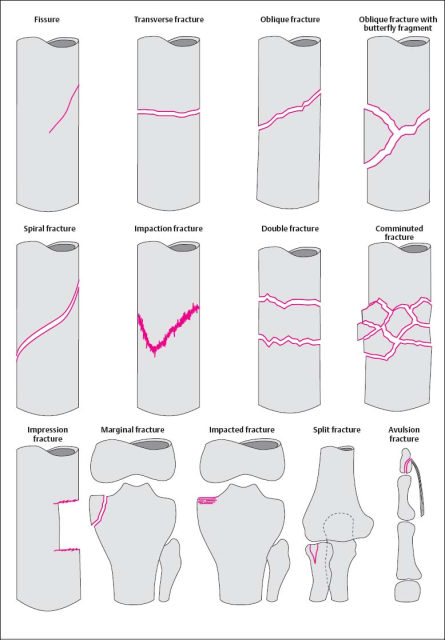
Fig. 1.20 Summary of the most important fracture types.
Special Considerations in the Pediatric Age Group
Trauma to the epiphysis and growth plate: The Salter-Harris classification is the most widely used classification applied to physeal injuries (Figs. 1.21, 1.24).
Type I: The epiphysis is completely separated from the metaphysis without evidence of osseous involvement.
Type II: Fracture through the epiphysis with a metaphyseal ‘corner’ fragment.
Type III: Intra-articular extension of a fracture of the epiphysis with involvement of the growth plate. The epiphyseal fragment can be displaced.
Type IV: Vertical fracture that crosses epiphysis, growth plate and metaphysis.
Type V: Compression of the growth plate (risk of premature closure of the growth plate).
Buckle or torus fracture: This is an impaction injury of the metaphysis, causing the cortex to buckle. It is frequently asymmetric with one side of the cortex more involved than the other and might even be invisible on one side (Fig. 1.22).
Greenstick fracture: This is an incomplete fracture leaving a portion of the cortex and periosteum intact (Fig. 1.23).
Growing fracture: Skull fractures in infants can grow due to development of a ‘leptomeningeal cyst’ that protrudes into the fracture line and causes it to widen as a result of marginal erosion.
Toddler’s fracture: This is an oblique or spiral fracture, primarily seen in the tibia, without displacement of the fracture fragments. It is a torsional injury found in children who are just beginning to walk.
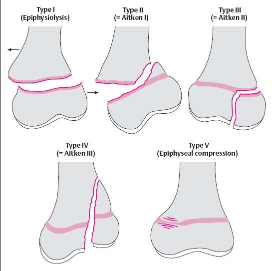
Fig. 1.21 Classification of the fractures involving the growth plates after Salter and Harris. Aitken’s classification is shown in brackets.
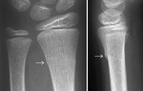
Fig. 1.22 Buckle fracture in a 9-year-old girl.
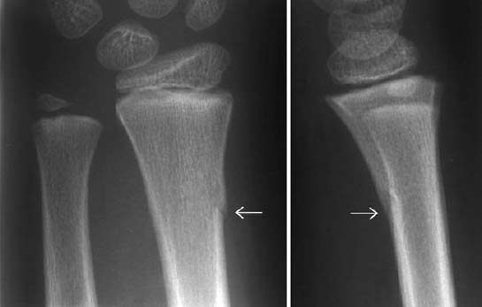
Fig. 1.23 Creenstick fracture in a 7-year-old girl. Only one side of the cortex is fractured.
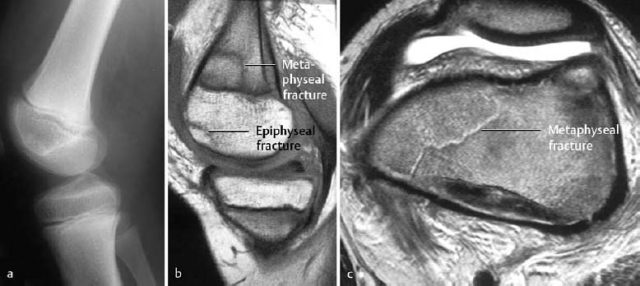
Fig. 1.24 Unusual fracture in the pediatric age group. Fracture across the metaphysis (corresponds to the Salter-Harris type II fracture), together with a subchondral fracture of the epiphysis (cartilage intact). a Unremarkable radiograph, b sagittal T1-weighted SE sequence, c axial T2-weighted sequence at the level of the femoral metaphyses.
Fractures of the articular surfaces (chondral and osteochondral fractures)
 The most important biomechanical properties of hyaline cartilage are protection against excessive strain and providing a smooth surface for the joint. These properties are determined by the chemical composition and the complex spatial interaction of the extracellular matrix of the cartilage. The matrix is primarily composed of water and macromolecules (collagen, proteoglycan, and other proteins). Hyaline cartilage consists of several layers, and the deep calcified zone and the subchondral bone are closely intertwined. An avulsion of the cartilage (traumatic separation) occurs primarily between the deep calcified and the juxta-articular noncalcified cartilage.
It is known from experimental studies that compression and trabecular fractures of the subchondral bone can occur without injury to the cartilage. This can be attributed to the greater elasticity of the cartilage in comparison to the subchondral trabecular osseous structure.
Fractures of the joints can be divided into typical skeletal fractures with articular involvement and specific fractures confined to the cartilage and subchondral bone. The latter fractures are caused primarily by pressure directly transmitted onto the cartilage by a vertical load. Concurrent shearing and rotatory load can not only increase the pressure on the articular surface but can also avulse cartilaginous fragments (with or without attached bone) from the articular surface.
 Frequent causes of articular surface fractures are torsion or supination/pronation injuries and these are often associated with ligamentous injuries.
The clinical findings are nonspecific, but a hemorrhagic joint effusion is invariably present. This finding can also be associated with any trauma involving the intra-articular structures.
Dislodged chondral or osteochondral fragments must be surgically reattached, but shallow articular compression deformities can be treated conservatively.
Location: The principal sites of involvement are the ankle and knee, including the patella. Other less common locations are the femoral head and humeral head.
 Chondral fractures occur primarily in children and adolescents, and osteochondral fractures occur primarily in adults.
 Technical considerations: If an osteo chrondral fracture of the ankle is suspected, a radiographic examination in three projections is indicated: AP, lateral, and AP oblique in slight internal rotation. The oblique view projects the articular surface of the talar trochlea without superimposition.
Ankle: The lateral osteochondral fractures of the talus are horizontally oriented and have a thin, small fragment (Fig. 1.28). The medial fractures are generally deeper and produce a crater-like defect.
Patella: The diagnostic evaluation rests on axial views, possibly obtained at different angles. Small contour defects are seen along the articular surface (Fig. 1.27).
Femoral condyles: The fracture line is invariably parallel to the articular surface. The following specific findings can occur alone or in any combination:
- linear densities in the subchondral bone (caused by superimposed fragments on the summation view),
- irregularity of the osseous contour (undulated, serrated; Figs. 1.25, 1.29),
- large avulsion with complete or partial separation of the fragments (Fig. 1.30),
- loose fragment in the joint capsule (Fig. 1.26).
When the epiphyses are unfused, chondral/osteochondral fractures can be mistaken for variants of the epiphyseal ossification. This will be addressed further (see pp. 128 ff).
 Conventional radiography has a high rate of false negative findings. For example, up to 30% of ankle fractures are overlooked.
 MRI is the imaging method of choice for the definitive evaluation of altered articular surfaces.
Technical considerations: The examination protocol offers several sequences. The recommended sequences are STIR, T1-weighted, and T2-weighted (turbo) spin echo and, for more comprehensive evaluation of cartilage, gradient echo sequences. The selection of section planes depends on the anatomy and the expected site of the injury. Images should be obtained in at least two planes.
With a properly selected examination technique, MRI should disclose the findings needed for the clinically relevant differentiation between injuries with cartilaginous defects and those with intact cartilage.
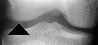
Fig. 1.25 Osteochondral fracture, seen only as irregular contour of the femoral condyle.
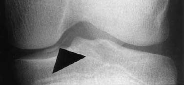
Fig. 1.26 Osteochondral fracture with loose fragment.
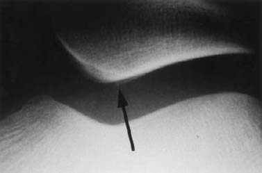
Fig. 1.27 Osteochondral fracture of the retropatellar articular surface.
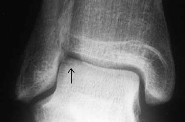
Fig. 1.28 Osteochondral fracture of the lateral aspect of the talar trochlea.
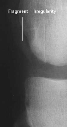
Fig. 1.29 Osteochondral fracture of the lateral femoral condyle. Shell-like osseous fragment and irregular condylar contour.
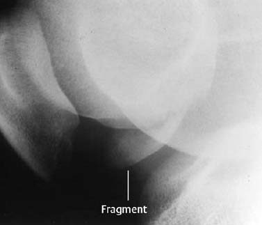
Fig. 1.30 Large osseous fragment of osteochondral fracture of the femoral condyle.
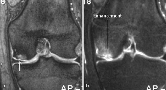
Injuries with cartilage defects: The major discriminating feature distinguishing strictly chondral lesions from osteochondral fractures is contour irregularity (Figs. 1.32, 1.33).
Injuries of the articular surface with intact cartilage: The following distinctions have to be made
- subchondral impaction (Fig. 1.31):
This produces a subtle depression of the subchondral bone parallel to the articular surface. Occasionally, scalloped signal changes and fracture lines are observed.
- subchondral trabecular fracture (bone bruise):
This represents bone marrow edema detectable by MRI without subchondral impaction.
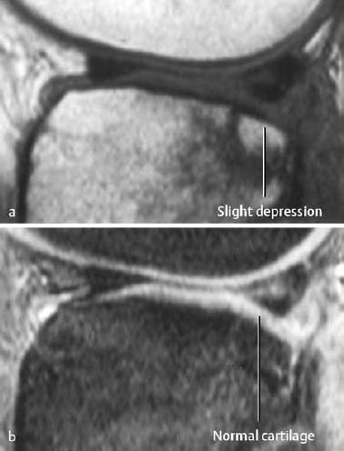
Fig. 1.31 Subchondral impaction with normal overlying cartilage. a T1-weighted SE image, b CRE image.
Stress and Insufficiency Fractures
Stress can be defined as the load sustained by bone. Bone is a dynamic tissue and needs stress for its normal development. The mechanical response to stress determines the osseous texture. Absence of normal stress induces rapid osteoclastic resorption of cancellous and cortical bone as well as cessation of the osteoblastic activity, leading to disuse osteoporosis.
Stress is also placed on bone from muscular activity and body weight.
It is not entirely understood how stress shapes the mechanical function of bone, but evidence suggests that the adaptive process is mediated by microfractures. Bone subjected to more than normal stress responds with osteoclastic resorption. The osteoclastic cavities are subsequently filled with lamented bone. The formation of new bone is a slow process (weeks to months), and stress in excess of the normal levels results in an imbalance between bone resorption and bone formation for the first few weeks. Therefore, new periosteal and endosteal bone formation represents a passing reparative mechanism needed to support the transiently weakened bone, especially the critical cortex. This process is basically the same in cortical and cancellous bone.
This normal physiologic adaptive process to micro damage (stress) becomes pathologic whenever there is an imbalance between the damage and repair. Continued and repetitive imbalance causes fatigue fractures of the cortical and cancellous bone. If the excessive stress abates (e.g., joggers curtail their activity because of the pain induced by the disproportionally high stress of running), a fracture line may not become visible despite radiographically apparent periosteal reaction as an adaptation to the stress. This phenomenon is referred to as stress reaction rather than stress fracture (Fig. 1.34).
a T1-weighted CRE sequence after intravenous injection of contrast medium (indirect arthrography),
b T1-weighted SE sequence with frequency selective fat suppression following administration of contrast medium.
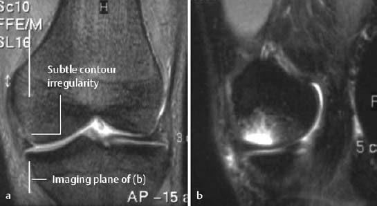
Fig. 1.33 Acute osteochondral fracture with surrounding edema laterally.
a Coronal T2-weighted CRE sequence with fat suppression,
b sagittal STIR sequence.
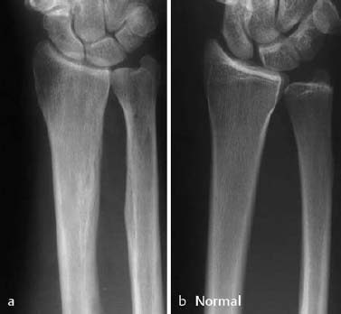
Fig. 1.34 a Stress reaction with periosteal and endosteal adaptation. The patient played volleyball for 30 years but was asymptomatic. The radiographic examination was obtained because of acute trauma. b Normal radiograph for comparison.
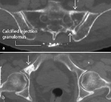
Fig. 1.35 Elderly female patient with pain for two years. a Remote insufficiency fracture of the right sacral ala. b The diagnosis of an insufficiency fracture is supported by a remote insufficiency fracture in the left superior ischial ramus (axial CT).
Fatigue fractures are divided into two categories, depending upon the underlying conditions of bone:
Stress fractures: The density and structure of bone are normal. Only the stressed portion of the bone is (reversibly) weakened according to the mechanism described above.
Insufficiency fractures: Normal or slightly above normal stress acts on a bone of abnormal density or structure. The pathologic fracture is a special case of insufficiency fracture. While the pathologic fracture occurs at a site of local bone loss, such as that caused by tumor destruction for instance, the insufficiency fracture generally affects bone of diffusely reduced bone mineral density (BMD) (Figs. 1.35, 1.37, 1.45).
Risk factors:
- Excessive mechanical strain, especially during walking.
- Estrogen deficiency in women.
- Elderly (osteoporotic bone).
- Reduced bone density from other causes (e.g., steroids).
 Location: The tubular bones of the appendicular skeleton as well as the axial skeleton can be affected. Insufficiency fractures primarily involve the femoral neck, distal forearm, spine, and sacrum, whereas stress fractures have a tendency to occur in the tarsal bones, tibia, and femur.
The clinical findings of insufficiency lesions consist of localized pain and soft-tissue swelling with overlying warmth. The stress fracture of the femoral neck can remain asymptomatic for a long time.
 It is important to remember that conventional radiography might show no abnormality for several weeks. Within the first few weeks, the radiographic sensitivity approaches 15–50%.
- A lamellated periosteal reaction is frequently the first radiographic sign.
- In selected cases, a subtle radiolucency and an indistinctly outlined cortex may be seen early.
- Endosteal thickening becomes discernible at a later stage of the process.
- The fracture line is usually apparent only after the periosteal reaction has appeared.
- An indistinctly outlined sclerotic zone is seen across the cancellous bone and the cortex (late stage, Fig. 1.38).
 Bone scintigraphy with Tc 99 m diphosphonate is well suited for the detection of stress and insufficiency fractures. A false negative finding is extremely rare.
A direct correlation exists between the intensity of tracer uptake and the extent of the stress fracture. Stress fractures appear as ill-defined focal areas of increased uptake, primarily in the cortex (Fig. 1.36).
Bone scintigraphy also reveals clinically asymptomatic lesions. Though the nature of these lesions cannot always be established, they are often attributed to stress reactions that have not yet become clinically apparent and have not yet induced any radiographic abnormalities.
Above all, bone scintigraphy contributes to the evaluation of anatomically complex osseous structures. Sacral insufficiency fractures present as linear or H-shaped radionuclide accumulation (the so-called ‘Honda sign’); this latter pattern is essentially pathognomonic of stress injury and not malignancy.
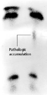
Fig. 1.36 Stress fracture of the tibia in a 6-year-old boy, with only minimally increased osseous uptake.
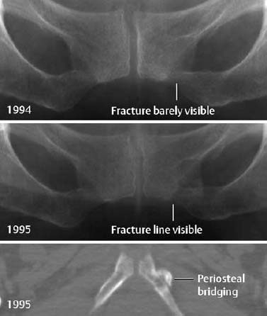
Fig. 1.37 Insufficiency fracture in the presence of severe osteoporosis.
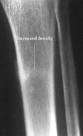
Fig. 1.38 Remote stress fracture in a marathon runner, seen as a subtle band of increased density.
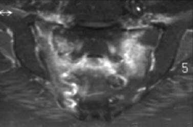
Fig. 1.39 Bilateral insufficiency fractures of the sacrum. Enhanced T1-weighted MR sequence with fat suppression showing the ‘H’ configuration (‘Honda sign’).
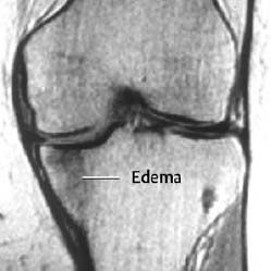
Fig. 1.40 Insufficiency fracture of the tibial plateau in an overweight osteoporotic woman with pain for three weeks.
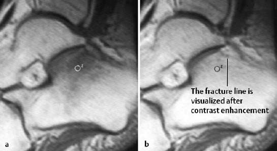
Fig. 1.41 Insufficiency fracture of the calcaneus, T1-weighted spin echo sequence before (a) and after (b) administration of contrast medium. After enhancement, the fracture line is seen as a band of decreased signal intensity.
 CT is a good method for delineating fracture lines, especially those in the sacrum, tarsal bones, and tubular bones. A definitive diagnosis can usually be made if the fracture line is surrounded by reactive sclerosis (Figs. 1.35, 1.37, 1.44).
 MRI is an extremely sensitive method for the detection of stress and insufficiency fractures since both conditions are associated with a bone marrow edema and can be used as an alternative to bone scintigraphy (Figs. 1.39, 1.40, 1.41, 1.43). The most helpful sequences are STIR images and T1-weighted and T2-weighted images. A fracture line is not always visualized, and in cases where the MR findings are nonspecific, osteomyelitis should be included in the differential diagnosis. In selected cases, enhancement with Gd-based contrast medium might help delineate the fracture line, which remains of low signal intensity relative to the enhancing edematous bone marrow (Fig. 1.41).
 Osteoid osteoma: The radiographic findings of this lesion are a round radiolucency surrounded by an irregularly outlined sclerotic rim without evidence of a linear component perpendicular to or at an acute angle with the cortex found in stress fractures.
Chronic osteomyelitis, another cause of diffuse cortical thickening usually involves the entire cortical circumference. Linear radiolucencies are not seen in this condition.
On MRI, the differential diagnosis includes an acute bone infarct, especially after radiotherapy to the pelvic region. In this setting differentiation of infarct from stress fracture can be difficult. Bone infarcts show a diffuse enhancement of bone marrow edema, and CT can be helpful in certain cases to search for fracture lines.
Pathologic Fracture
This condition represents a special case of insufficiency fracture. It is a fracture that develops in an osseous structure weakened by tumor or tumor-like conditions. These injuries are usually caused by inadequate stress or minor trauma (Figs. 1.42, 1.46).
The commonest pathologic fracture is one occurring through a juvenile bone cyst or a nonossifying fibroma. Any osseous tumor, especially metastases, can be the underlying cause of a pathologic fracture. However, the notable exception to this rule is primary or secondary bone-forming tumors, such as osteosarcoma and osteoblastic metastases, which rarely result in a pathologic fracture.
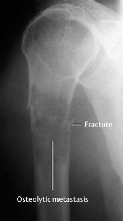
Fig. 1.42 Pathologic fracture of the proximal humerus through an osteolytic metastasis from thyroid carcinoma.
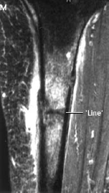
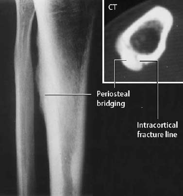
Fig. 1.44 Pain for three months, no discernible fracture line: Stress fracture with periosteal new bone formation.
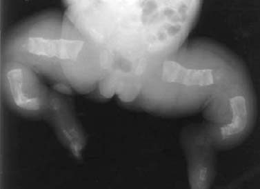
Fig. 1.45 Insufficiency fracture in osteogenesis imperfecta.
Below:
Fig. 1.46 Pathologic fracture in fibrous dysplasia (a). The patient suffered minor trauma. b Control radiography after internal fixation. The fibrous dysplasia was initially overlooked and only recognized after removal of the internal fixation device. c Conventional tomography.
Fracture Healing
 Primary (direct) and secondary (indirect) healing of the fractures returns osseous stability by restoring the original tissue.
Primary Fracture Healing
Definition: Primary healing is characterized by the absence of callus formation and requires:
- Contact between fragments with a maximum fracture gap of 0.5 mm. Internal compression fixation of the fragments increases the chance of a primary fracture healing.
- Immobilization of the fracture fragments (e.g., internal fixation).
- Adequate blood supply and viability of the fragments.
The fracture fragments unite by direct extension of the Haversian canals from one fragment to the other (‘contact healing’), or by the formation of lamellar bone, which is later replaced by longitudinally oriented osteons (‘gap healing’). The periosteal or endosteal mesenchymal cells are not activated in this setting.
 |
|
Visualized interosseous or periosteal callous formation indicates the formation of ‘restless’ callus, followed by fixation callus. Furthermore, widening of the fracture line or the appearance of a ‘new’ fracture line reflects osseous resorption of the fracture fragments and indicates an impaired primary fracture healing.
Secondary Fracture Healing
A widened fracture line or inadequate mechanical fixation of the fracture fragments results in secondary fracture healing, consisting of the formation of a ‘periosteal cuff’ around the fracture gap. This cuff arises from connective tissue and represents mesenchymal new bone formation. In addition to connective tissue proliferation, cartilage is usually formed by metaplasia and ultimately transformed into osseous tissue. Thus, the original structure is restored via a detour (lamellar osseous tissue, osteons).
Secondary osseous healing passes through characteristic stages and their corresponding radiographic findings are shown in Table 1.4.
 Trabecular fractures initially show increased density. Within weeks, the increased density resolves and is replaced by normal trabecular texture. A periosteal reaction always indicates cortical involvement.
Osseous consolidation of a fracture should be assessed clinically first. The radiographic signs usually lag behind the clinical signs.
The clinical signs of an osseous consolidation (not to be equated with complete fracture healing) are:
- stability on physical examination,
- lack of pain,
- ability to bear weight.
Radiographic Signs of Osseous Consolidation
- The osseous bridging of the fracture is solid.
- The fracture callus is of homogeneous density.
- The density of the fracture callus equals the density of the cortex.
- These findings must be seen in at least two projections.
Caution: Underexposed films overestimate the degree of osseous bridging.
Basic Principles of Fracture Treatment
The conservative (closed) treatment follows three approaches:
- Primary functional treatment (without cast). This requires adequate axial relationships and exercise stability; for example, a subcapital fracture of the humerus in an elderly person.
- Repositioning and immobilization by casting, for instance, a distal radial fracture.
- Repositioning and immobilization by means of traction; for instance, a femur fracture.
The goals of operative (open) therapy are to restore the normal anatomic relationship of the axial planes and articular surfaces and to stabilize fracture fragments. Several approaches are available and can be combined.
- Internal fixation by screws; for example, avulsion of juxta-articular or joint-bearing fragments,
- Internal fixation by compression plates and screws,
- Internal fixation by wire fixation (cerclage); for example, the olecranon and patella,
- Intramedullary fixation; for example, by rod and pins,
- External fixation; for example, the compound fracture of the lower leg.
| Time after fracture | Healing phases | Radiographic findings |
|---|---|---|
| First days | Hematoma due to tearing of bone, periosteum, bone marrow and surrounding soft tissues ‘Inflammation phase’ Migration of multiple cell types | 3rd – 14th day: Demoralization of bone. The fracture line becomes clearly visible (due to bone resorption) From the 10th day: New periosteal callus formation begins (Fig. 1.47) |
| Up to the 3rd – 4th week | ‘Granulation phase’ Fibrous conversion of the hematoma caused by proliferating tissue with collagenous fibers and capillary growth. Differentiation (migration) of osteoblasts (→ bone formation), chondroblasts (→ cartilage formation). Formation of ‘soft’ callus | From the 14th day: Increasing bone density in the fracture gap. Indistinct fragment borders. Cuff-like density around the fracture |
| From the 3rd – 4th week to the 3rd – 4th month | ‘Conversion to hard callus’ Mineralization of the matrix Formation of woven bone | From the 6th – 8th week: Bridging and consolidation The bone is well demarcated and dense |
| From the 4th month | ‘Modeling’ and ‘remodeling’ Conversion of woven bone into lamellar bone Restoration of normal bone contour and of the marrow space | Complete incorporation of the bone until complete restoration (Figs. 1.48, 1.49) |
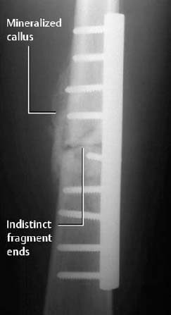
Fig. 1.47 Callus formation following internal fixation of a femoral fracture. Indistinct fracture line.
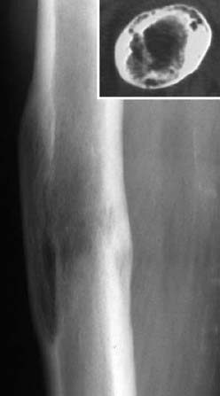
Fig. 1.48 Status 4 years post-femoral fracture. Since the history of previous trauma was not known, the finding was initially diagnosed incorrectly as metastasis from the patient’s known breast carcinoma.
Fig. 1.49 Status 3 years post-green-stick fracture. Subtle post-traumatic cortical thickening.
Delayed Fracture Healing
Delayed fracture healing takes place in the following situations:
- extension of the fracture into the joint,
- elderly patients with slow osseous metabolism,
- poor alignment of the fracture fragments,
- inadequate immobilization of the fracture fragments,
- extensive soft-tissue injury (poor condition for perfusion!).
Fracture healing is categorized as delayed (impaired) if the time of healing exceeds twice the expected time period (about 4 to 6 months). The primary causes are:
- inadequate immobilization,
- impaired perfusion,
- infection.
A delay in fracture healing can result in a pseudarthrosis.
Pseudarthrosis
Non-union refers to absent healing after about 6 to 8 weeks. Both primary and secondary fracture healing can develop into pseudarthroses (Figs. 1.50, 1.51).
Causes
- inadequate immobilization,
- soft tissues interposed in the fracture gap,
- extensive loss of osseous substance,
- inadequate blood supply,
- infection (with/without sequestration).
Classification
Based on appearance (descriptive):
- hypertrophic form,
- atrophic form,
- defect with pseudarthrosis.
Based on viability (biologic):
- biologically reactive pseudarthroses.
This type is caused by bridging of the fracture gap by fibrous tissue or inadequate callus formation, resulting in mobility of the fragments.
- biologically nonreactive pseudarthroses. This group represents nonviable pseudarthroses with severely impaired blood supplies directly beneath the ends of the fracture fragments. They are usually caused by large defects, necroses, and infections. The therapeutic goal is to restore stability with autologous cancellous bone grafts. Ultrasound may also be used for that purpose.
 Hypertrophic type:
- The fracture fragments are smoothly outlined and sclerotic.
- The surrounding bone is eburnated.
- There is no evidence of osseous bridging.
- The fracture fragments are widened (‘elephant foot’).
- The fracture fragments can be rounded.
Atrophic type:
- There is only minimal evidence of sclerosis of the ends of the fracture fragments.
Complications after Fractures
Infection
Infection can be a primary complication of the injury or a secondary complication after operative therapy. See Post-traumatic Osteomyelitis in Chapter 2.
Avascular Necrosis (AVN)
Avascular necrosis develops if a fracture or dislocation deprives the bone of an adequate blood supply.
Predilection: femoral head, scaphoid, humeral head (Figs. 1.52, 1.53).
Avascular necrosis of the femoral head constitutes the most frequent complication of a subcapital femoral neck fracture, hip dislocation, or slipped femoral epiphysis.
The diagnostic evaluation of patients in whom AVN is suspected includes conventional radiography, MRI, and bone scintigraphy (see Avascular Necrosis, pp. 218 ff).
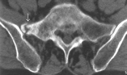
Fig. 1.50 Pseudarthrosis following insufficiency fracture 2 years ago. Chronic back pain.
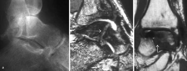
Fig. 1.51 a Surgically treated talar fracture with development of a pseudarthrosis. Metallic fixation device removed. b T2-weighted CRE sequence, c T1-weighted SE sequence.
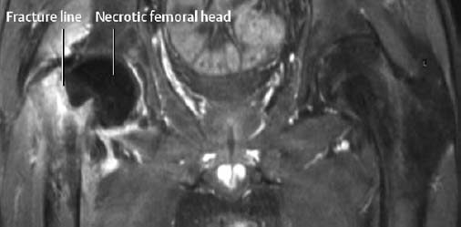
Fig. 1.52 Avascular necrosis of the left hip following medial subcapital fracture of the femoral neck. There is no perfusion of the femoral head on the T1-weighted sequence with fat suppression following enhancement.
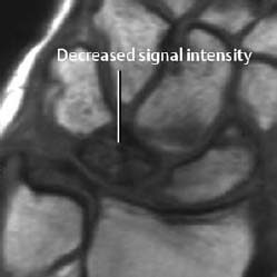
Fig. 1.53 Avascular necrosis (osteonecrosis) of the lunate (Kienböck’s disease), T1-weighted SE image.
Myositis Ossificans
Heterotopic ossification of the soft tissues adjacent to bone is referred to as myositis ossificans. It is post-traumatic, but can occur in the absence of a fracture. Typically it appears as diffuse ossification in the soft tissues with corresponding changes on conventional radiographs, CTand MRI. (See Myositis Ossificans, pp. 286 ff).
Disuse Osteoporosis
Disuse osteoporosis is an acute form of demineralization due to immobilization.
It can have the following radiographic manifestations:
- Decreased bone density confined to the cancellous bone without cortical involvement. The small trabeculae resolve, with thickening and indistinctness of the remaining trabeculae.
- Patchy decrease in bone density seen as ovoid and round, but also irregularly outlined, radiolucencies. These changes are frequently observed in older patients and in the hands and feet.
- Radiolucent lines. They are usually juxta-articular, and are most frequently seen along the old growth plates.
- Punctate and patchy radiolucencies with the cortex (enlarged Haversian canals).
These changes generally are combined in different degrees (Fig. 1.54).
 Senile osteoporosis: This is a diffuse loss of bone not confined to one extremity. It can be excluded only by comparing radiographs of both the normal and the immobilized extremities. Sudeck’s atrophy: This is primarily a clinical diagnosis (see next section). The radiographic findings are almost identical to those of disuse osteoporosis.
Post-traumatic Degenerative Osteoarthritis
This complication occurs most frequently following fractures involving the articular surface or after chondral or enchondral fractures. It is caused by the incongruity of the articular surface which leads to premature abrasion and subsequent destruction of the cartilage. The resultant secondary degenerative osteoarthritis follows the stages found in primary degenerative osteoarthritis (Fig. 1.55).
Any altered axial orientation after a fracture changes the weight bearing of the joint. This is another mechanism that can induce degenerative osteoarthritis, particularly in the weight-bearing joints.
Post-traumatic Growth Disturbance in Children and Adolescents
Bone growth can be affected by many different situations. Any traumatic change involving a growth plate can potentially cause growth acceleration, generally explained by the hyperemia from trauma. This growth acceleration is transient and compensated by subsequent growth retardation.
Post-traumatic growth retardation has greater clinical implications. It is generally caused by an ossified growth plate. Partial involvement of the growth plate will induce asymmetric growth retardation while involvement of the entire growth plate will shorten the affected limb.
Partial fusion of the central region of the growth plate causes so-called ‘cupping’, which consists of cone-like widening of the epiphyses toward the metaphysis of the affected tubular bone.
Foreign Body Reaction
Foreign material retained in tissue generally becomes encapsulated and causes no irritation. However, it can represent a source of chronic irritation with subsequent bone resorption and reactive sclerosis (Fig. 1.56). In joints, foreign bodies generally will induce chronic synovitis.
Post-traumatic Cyst Formation around the Fracture Site
Large encapsulated hematomas that do not contribute to the healing process can form within fractures. Rarely, they can create large cystic osseous defects within a stable and load-bearing fracture. This phenomenon is encountered in greenstick fractures but can also occur in ‘normal’ fractures. The radiographically visualized radiolucency can be central or peripheral (Fig. 1.57) and any differential diagnostic problems can usually be solved by MRI. These post-traumatic cysts regress spontaneously at a slow rate over several years.
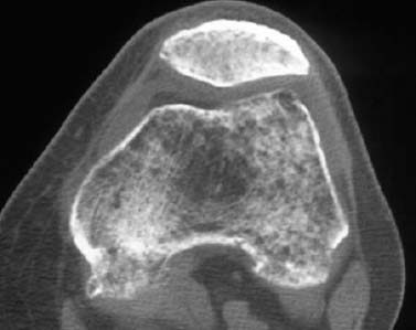
Fig. 1.54 Severe disuse osteoporosis following femoral neck fracture with long immobilization.
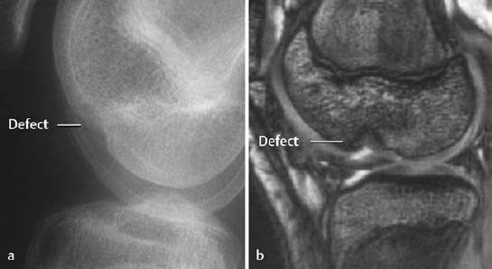
Fig. 1.55 Residual defect following osteochondral fractures 2 years earlier. There is a predisposition to degenerative osteoarthritis in this setting.
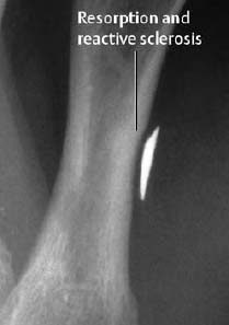
Fig. 1.56 Osseous reaction to retained metallic foreign body.
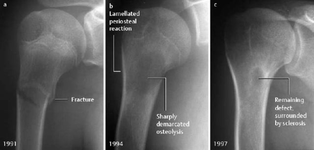
Fig. 1.57 a Proximal humeral fracture in a 13-year-old girl. b 3 years later: large central radiolucency caused by a hematoma. Lamellated periosteal reaction as evidence of repair. c After a further 3 years: incomplete resolution of the osteolytic area.
Reflex Sympathetic Dystrophy (RSD)
Synonyms: Sudeck disease, Sudeck’s atrophy, algodystrophy.
Causalgia: Manifestation of reflex sympathetic dystrophy with severe pain.
Shoulder-hand syndrome: Reflex sympathetic dystrophy of the hand secondary to humeroscapular periarthritis.
Because of its still unexplained pathogenesis and unspecific presentation, reflex sympathetic dystrophy is known under various names. According to the latest definition published by the American Association of Hand Surgery, reflex sympathetic dystrophy is a pain syndrome associated with functional loss and detectable autonomous dysfunction. The original description by Sudeck seems to express the relevant findings best:
 Reflex sympathetic dystrophy is a painful acute osteoporosis with soft-tissue swelling or atrophy.
 Reflex sympathetic dystrophy is usually posttraumatic, typically following distal radial or tibial fractures, but it can be induced by a variety of other conditions including myocardial infarction and cerebrovascular accidents. In some cases, no predisposing condition can be found.
The pathophysiology of this condition is unclear but the most frequently postulated theory proposes that afferent pain stimulates a hyperactive sympathetic nerve system to induce a change in blood flow that increases bone resorption. Recent research supports Sudeck’s original hypothesis of excessive regional inflammatory reaction.
 The diagnosis is made if four of these five clinical criteria are fulfilled:
- diffuse pain,
- change in skin color,
- diffuse soft-tissue edema,
- different skin temperature,
- limited range of active motion.
The complaints increase with weight bearing.
Clinical course: Three stages are observed:
- Inflammatory stage: burning pain, soft tissue swelling, weakness and hyperesthesia.
- Dystrophic stage: vasospasm or vasodilatation, skin changes (atrophy, pigmentation, hyperhidrosis, nail changes), contractures.
- Atrophic stage: skin atrophy, resolution of other symptoms.
Therapy: Conservative therapy, initially with lymph drainage, cryotherapy, later with thermotherapy and active physical therapy.
 The radiographic changes are nonspecific and, depending on the stage, can consist of soft-tissue swelling or atrophy, as well as regional osteoporosis. Initially, the osteoporosis is patchy or band-like and later changes to a more uniform demineralization with indistinct texture of the cancellous bone (Figs. 1.58, 1.59). The subchondral lamella is frequently lost and the cortex can show subperiosteal, intracortical, or endosteal resorption.
In rare cases, a fracture is superimposed on reflex sympathetic dystrophy.
 Bone scintigraphy with Tc 99 m diphosphonate shows typical changes in the soft-tissue phase (5-15 minutes after the injection of tracer) and in the bone phase (at about 3 hours) (Fig. 1.60). Increased uptake around the joint, predominantly along the cortex, often extends to the entire affected extremity with accentuation distally.
In the third (atrophic) stage, the scintigraphic findings can return to normal.
 MRI shows soft-tissue swelling (Tl-weighted images, STIR sequences) and soft-tissue enhancement. Bone marrow changes are rare (Fig. 1.61).
 Arthritis: The regional osteoporosis is confined to the affected joints, the soft-tissue swelling is fusiform, the joint space is narrowed, and osseous erosions are found.
Disuse osteoporosis: It cannot be distinguished on the basis of the demineralization pattern. The disuse osteoporosis is painless and not associated with soft-tissue swelling. Bone scintigraphy does not show hyperperfusion.
Bone contusion: The finding is localized and seen as bone marrow edema on MRI.
Acute and chronic osteomyelitis: MRI invariably shows bone marrow changes which are absent in reflex sympathetic dystrophy.
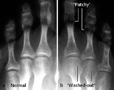
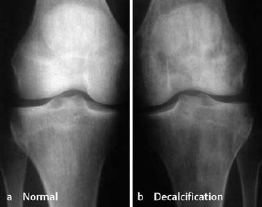
Fig. 1.59 Reflex sympathetic dystrophy of the left leg with patchy and striate radiolucencies.
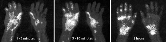
Fig. 1.60 Reflex sympathetic dystrophy following partial fasciectomy for Dupuytren contracture. The typical bone scan findings are diffuse hyperemia as well as lateralization of the early and late blood pool images, followed by increased uptake in the carpal and metacarpal bones in the bone phase.
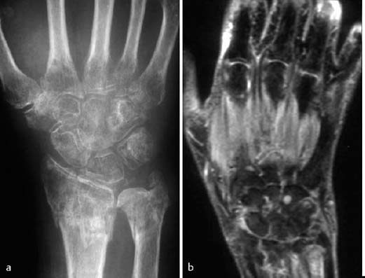
Fig. 1.61 Reflex sympathetic dystrophy of the right hand three months following a distal radial fracture. Osteoporosis with indistinct trabecular lines and patchy radiolucencies. The STIR sequence (b) shows increased signal intensity of the soft-tissues and an absence of bone marrow edema.
Trauma-induced Soft-Tissue Changes
Tendon Injuries
Tendons attach muscles to bone, usually bridge a joint, and have a high tensile strength. To function normally, they need an intact gliding bed, usually formed by a coarsely textured layer of connective tissues. Where the gliding range is wide, the tendons are surrounded by a sheath (e.g., fingers).
 Traumatic rupture of the tendon results in tendon and muscle retraction. Small gaps can be spontaneously bridged by the ingrowth of soft tissues.
Mechanism of trauma:
- separation,
- rupture,
- degeneration (age, sports-induced stress, inflammation, long-term corticosteroid therapy, hypercholesteremia, diabetes mellitus).
 Acute injuries to the tendons are easily detected by MRI. Since these injuries are diagnosed clinically, MRI is rarely performed.
On T2-weighted images there is increased signal intensity seen in an irregular gap of low or absent intensity in the tendon (Fig. 1.62b). The gap is filled with fluid and/or enhancing granulation tissue and the tendon is surrounded by localized or diffuse edema or hemorrhage.
The so-called, ‘chronic tear’ of ligamentous degeneration is seen as a focal area of increased intensity in a diffusely thickened tendon on T2-weighted SE MR images. Postoperatively, the sutured tendon is thickened and shows heterogeneously increased signal. The site of the suture often shows strong enhancement.
 A retracted tendon is easily detected ultrasonographically by comparison with the contralateral side (Figs. 1.63, 1.64). A tendon with degenerative changes is more difficult to evaluate. In general, the tendon is hypoechoic.
Ligamentous Injuries
Direct visualization of ligamentous structures requires MRI or sonography. Functional radiographic views (e.g., ‘stress views’) only provide indirect evidence of ligamentous lesions.
 Ligaments are of low signal intensity on both Tl-weighted and T2-weighted images. A complete tear, best appreciated on STIR or T2-weighted SE MR images, appears as a high signal area (edema, blood) within the substance of the ligament. The tear may also be seen on the short TE images (Tl-weighted or proton density). Images should be obtained in the plane that most optimally displays the ligamentous anatomy (see Special Traumatology: Knee, Ankle).
 Sonography is well suited to diagnose ligamentous injuries. While normal ligaments are seen as echogenic structures, injuries at the ligamentous insertion and involving the ligament itself are not only seen as continuity breaks but also as diffuse thickening and decreased echogenicity.
Muscle Injuries
Muscle fibers do not regenerate after injuries and muscular injuries result in a scar, which has less functional strength.
Types of injuries:
- Strain: Stretching of the muscle without exceeding its tensile strength. Hemorrhage occurs within the muscle.
- Crush: Blunt external force ruptures muscle fibers, possibly inducing areas of muscular necrosis.
- Rupture: This can occur after trauma to normal or degeneratively predamaged muscle. The muscle is partially or completely severed, but complete loss of function is rare.
 Diffuse edema and hemorrhage are the characteristic findings of acute as well as repetitive trauma and are easily identified as diffusely increased signal intensity on STIR and T2-weighted images (most conspicuous on turbo-SE sequences with fat suppression). The differentiation between sprain and (partial) tear rests on detecting a break in the ligamentous continuity. Tears result in large localized (hemorrhagic) fluid accumulations. MR findings are rarely seen in sprain or crush injury.
With immobilization of the affected extremity, the signal changes of a tear generally resolve within 14 days.
Intra- or intermuscular hematomas have a typical signal pattern which is related to the age of the hematoma. The signal intensity can be high on Tl-weighted and T2-weighted images. If the Tl-weighted images show a signal of higher intensity than that of normal fluid (edema), the diagnosis of a hemorrhage is established Fig. 1.65, 1.66). Older hematomas are surrounded by a rim of a signal void, which is attributed to hemosiderin deposits. This finding has to be differentiated from calcification, which appears as signal void as well. (The conventional radiograph helps to make this distinction.)
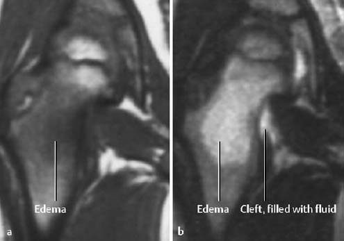
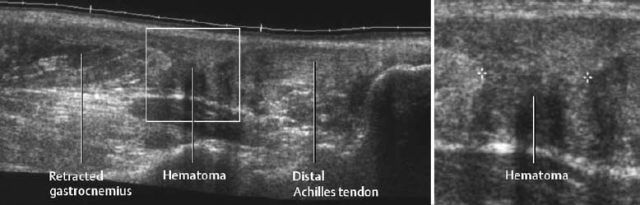
Fig. 1.63 Sonographic visualization of an Achilles tendon tear.
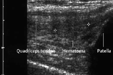
Fig. 1.64 Small hematoma as manifestation of a partial tear of the quadriceps tendon.

Fig. 1.65 Subfascial hyperintense hematoma of the calf without known injury. Clinical and sonographic findings were suggestive of tumor (T1-weighted sequence).
 A hematoma is sonographically detected as a hypoechoic or sometimes anechoic fluid accumulation. The musculature also loses its normal pennate texture. Often the hematoma cannot reliably be differentiated from synovial fluid extruded from a ruptured Baker cyst in the calf.
Rhabdomyolysis
The possible causes of loss of cellular integrity of muscle tissue are strain, trauma, burn, and exposure to toxins (drugs).
MRI may show no changes or only a slight decrease in signal intensity on the Tl-weighted image. In contrast, the affected muscle exhibits a marked increase in signal intensity on the T2-weighted image (Fig. 1.67).
Myositis Ossificans
Soft-tissue injuries can lead to traumatic myositis ossificans (see pp. 286ff).
Compartment Syndrome
The compartment syndrome refers to injury in an anatomically confined muscular compartment if elevated tissue pressure (caused by hematoma, edema) leads to decreased perfusion and subsequent ischemia. The end result is often hemorrhage and necrosis. MRI can display these changes and determine the extent of the soft-tissue damage (Fig. 1.68). Late complications of the compartment syndrome are radiographically visualized dystrophic calcifications (Fig. 1.69).
Glossary
Burns: Burn-induced osseous and articular changes usually depend on the size of the burned area.
The radiographic findings reflect the effect of ischemia (endothelial capillary damage) and the concurrent hyperemia of the remaining vascularized tissue:
- Focal or regional osteoporosis (immobilization or vasomotor reflex as probable cause).
- Periosteal reaction, similar to that of hypertrophic osteoarthropathy.
- Periarticular calcifications and ossifications, especially around hip, elbow, and shoulder.
- Progressive joint destruction, probably due to subchondral osteonecrosis along the articular fossa.
- Acro-osteolysis
Caution: Extensive burns frequently lead to secondary infections. They cause a multifarious picture and complicate the above-mentioned radiographic findings.
Frostbites: Temperatures below 8–12°C damage soft tissues and nutrient vessels by causing decreased blood flow, erythema, and edema. The affected parts are usually the most distal ends of the extremities.
The most prominent radiographic sign of frostbitten bones is subchondral osteonecrosis, especially in the phalanges of the hands and feet, as well as in the metacarpal and metatarsal bones.
The findings can progress to osteolysis (e.g., acro-osteolysis) (Fig. 1.70).
Freezing-induced arthropathy is known in forest workers. The small tubular bones (fingers, toes) show evidence of (erosive) polyarthritis with cystic transformation of the articulating bones, subchondral sclerosis, and marginal osteophytes. The joint space is narrowed and the joints are misaligned.
Changes caused by freezing have been described in the ossification centers of the growing skeleton of adolescents.
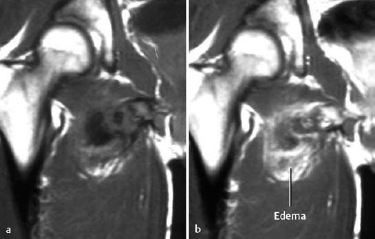
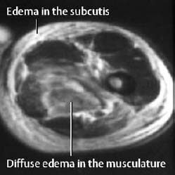
Fig. 1.67 Rhabdomyolysis in a drug addict (T2-weighted image).
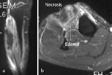
Fig. 1.68 Muscle necrosis in compartment syndrome (T1-weighted sequence after frequency selected fat suppression and enhancement), a Coronal, b axial imaging plane.
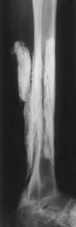
Fig. 1.69 Soft-tissue calcifications following compartment syndrome 24 years previously.
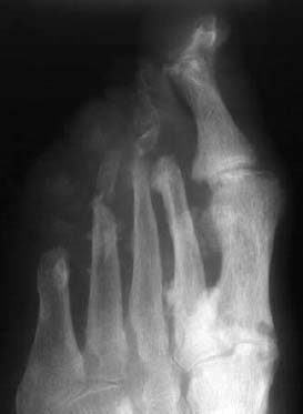
Fig. 1.70 Severe osteolysis of the second to fifth ray after frostbite.
Radiologic Reporting of Fractures
The radiologic report should address the following items:
- Where is the fracture? To describe the level of the fracture, the long tubular bones should be divided into three equal parts (e.g., at the junction of middle and distal thirds).
- What type of fracture? The direction of the fracture line (transverse, oblique, spiral, etc.) should be stated (see (Fig. 1.20).
- Where are the fracture fragments? The position of the distal fragment should be described in relation to the proximal fragment. Any angulation or tilt should be expressed in degrees. Varus position refers to medial angulation of the distal fragment toward the midline of the body, and valgus position refers to lateral angulation of the distal fragment away from the midline of the body. Additional anterior or posterior angulation in the second plane is seen on the lateral projection.
- Any translational displacement of the fracture fragments should be described (e.g., the distal fragment is displaced laterally, medially, etc., by one shaft width or one cortex width).
- Are the articular surfaces involved? Is there any associated dislocation or subluxation?
- Is the fracture complete or incomplete?
Follow-up radiographs should address:
- Position of the fragments in comparison with the initial and preceding examination.
- Amount of callus formation.
- Extent of osseous bridging and remodeling.
Search for possible complications:
- Osteomyelitis: Did radiolucent areas appear? Are indistinct radiolucent halos seen around internal fixation devices (e.g., screws, nails, pins)?
- Is there any evidence of osteonecrosis?
What Should Be Avoided?
Judgmental terms, such as ‘good’, ‘adequate’, ‘acceptable’, or similar expressions, should be avoided.
Likewise, statements describing the osseous bridging as ‘solid,’ ‘delayed,’ ‘partial,’ or ‘absent’ should not be used. These statements require an intimate familiarity with the clinical condition. Instead, the callus should be described by its appearance (how does the callus look?) and it should be stated whether its appearance indicates osseous bridging or not. Furthermore, it should be stated whether the fracture line is still visible.
It should be kept in mind that it is difficult to judge any possible rotation of the fragments on conventional radiographs. If a clinically relevant rotation is suspected, CT or MRI should be recommended.
| Fracture | Average time for healing |
|---|---|
| Skull | 3–6 weeks |
| Clavicle, scapula | |
| Sternum, ribs | |
| Humeral head | |
| Distal humerus | |
| Elbow | |
| Radial head | |
| Distal forearm | |
| Metacarpals, fingers | |
| Metatarsals, toes | |
| Humeral shaft | 6–8 weeks |
| Radial and ulnar shaft | |
| Distal tibia and fibula | |
| Tibial shaft | 8–10 weeks |
| Femoral shaft | |
| Carpal bones | 10–14weeks |
| Femoral neck | |
| Pelvis | |
| Distal femur | |
| Tibial plateau | |
| Tarsal bones/calcaneus |
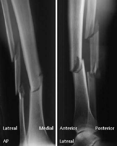
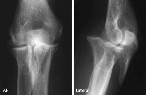
Fig. 1.72 Typical findings: trauma films. Oblique fracture of the proximal ulna with articular involvement and anterior ulnar dislocation. There is no displacement of the olecranon fragment.
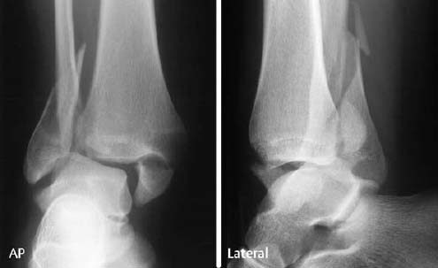
Fig. 1.73 Typical findings: trauma films. Trimalleolar fracture-dislocation of the ankle with posterolateral displacement and medial angulation of the talus. There is a fibular fracture at the level of the ruptured interosseous membrane with medial angulation (approximately 20 degrees). The fractured medial malleolus is displaced laterally by about 8 mm and the posterior cortical fragment of the tibia (Volkmann triangle) is displaced upward by 5 mm.
Special Traumatology
Skull and Spine
Fractures of the Cranial Vault
Fractures of the cranial vault are differentiated according to location, mechanism, and configuration. Depending on the severity and type of causative force, three fracture types can be distinguished:
- linear fractures (Figs. 1.74, 1.75),
- depressed or comminuted fractures (Fig. 1.76),
- punched-out fractures.
Linear Fractures
These represent 80% of all fractures of the cranial vault and generally are temporoparietal, occipital, and frontal in location. Only the presence of intracranial complications (bleeding, edema, intracranial air, etc.) requires therapeutic intervention.
Caution: Linear fractures can be mistaken for sutures or vascular grooves; fracture lines cross sutures and vessels, are sharply delineated, and do not have a sclerotic rim (Fig. 1.74).
 Fractures that cross the groove of the middle meningeal artery can cause an epidural hematoma.
Depressed and Comminuted Fractures
These fractures generally are diagnosed by conventional radiography, but a complete diagnostic evaluation requires computed tomography to delineate the true extent of the intracranial displacement of the osseous fragments as well as any associated cerebral involvement (Fig. 1.76).
Punched-out Fractures
Depending on its angle and velocity, the penetrating force can result in a depressed, punched-out, or burst fracture.
Fractures of the Cranial Base
These fractures primarily involve the orbital roof, petrous pyramid, and occipital bone. The central areas of the cranial base are less often involved. Since the neurovascular structures pass through an aperture in the mechanically weak sites of the central cranial base, these fractures can be associated with considerable clinical findings (brain stem paralysis, paresthesia, vision loss, CSF fistula).
CT has become the exclusive imaging modality for the evaluation of the cranial base (Fig. 1.77).
Fractures of the Temporal Bone
Classification of Temporal Bone Fractures
Historically, these fractures have been categorized relative to the longitudinal axis of the temporal bone as longitudinal, transverse, and mixed fractures. This categorization is arbitrary, however, since many fractures follow a winding course through the temporal bone.
- Longitudinal fractures account for 70–80% of all fractures of the temporal bone and run along the longitudinal axis of the petrous pyramid (Fig. 1.78). Beginning in the region of the mastoid with involvement of the tegmen tympani (roof of the middle ear cavity), external auditory canal and temporomandibular fossa, the fracture line extends along the floor of the middle cranial fossa, continues anteriorly toward the apex of the pyramidal bone, and terminates at the carotid canal, foramen lacerum, foramen spinosa, or musculotubal canal. A fracture line directed toward the internal auditory canal (risk of facial nerve palsy) or even jugular foramen is less frequently observed. Longitudinal fractures are frequently associated with dislocated or fractured ossicles and almost invariably result in conductive hearing loss.
- Transverse fractures account for about 20% of all fractures of the temporal bone (Fig. 1.79). These fractures always follow the path of least resistance and run perpendicular to the long axis of the petrous pyramid. Thus, the fracture lines traverse the roof of the jugular fossa, the inner ear (with involvement of cochlea and vestibule), and finally the petrous ridge. The clinical findings depend on the course of the fracture line, with the spectrum ranging from hematotympanum, vertigo, and vestibular nystagmus, to complete hearing loss. The facial nerve is injured in 50% of cases.
- Complex or mixed fractures exhibit longitudinal and transverse components and often occur in conjunction with severe head trauma. Cerebrospinal fluid otorrhea or herniation of cerebral tissue through the fracture line are typical complications.
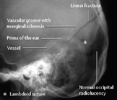
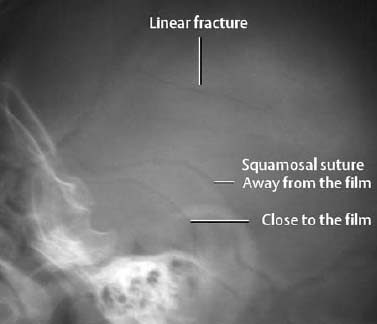
Fig. 1.75 Linear fracture in a child.
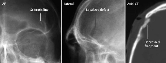
Fig. 1.76 Depressed fracture of the calvaria. Caution! This case illustrates that searching for radiolucent fracture lines is not adequate. A CTscan is necessary to determine the extent of the impression and to exclude intracranial injuries.
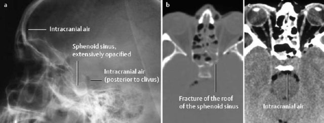
Fig. 1.77 Fracture of the sphenoid sinus as seen on conventional radiographs (a) and on axial CT (b bone window, c soft-tissue window). The conventional radiograph only provides indirect evidence of a fracture of the cranial base.
 Conventional radiography is still the basic examination, comprising AP, lateral, and submentovertical projections as well as special projections, such as Law and Stenvers views and, occasionally, the Mayer view Fractures of the temporal bone can be diagnosed on the basis of direct fracture signs (radiolucent line, contour break), indirect fracture signs (opacification of the mastoid cells, sphenoid sinus, external auditory canal, middle ear cavity), or by local pneumocephalus.
 This is the imaging method of choice for the evaluation of the traumatized temporal bone. The fracture signs are the same as those for conventional radiography. Furthermore, a change of the chain of the auditory ossicles (subluxation, dislocation, fracture) might be detected. Traumatic lesions of the stapes, however, are rarely adequately visualized.
 MRI is only indicated when injuries of intracranial structures or cranial nerves dominate the clinical findings or are otherwise suspected together with fractures of the temporal bone.
Fractures of the Facial Bones
Because of their pathogenesis, fractures of the facial bone are frequently multiple and complex.
The classification is always somewhat artificial since the traumatic pattern varies from patient to patient. It is clinically appropriate to make a distinction between localized and midfacial fractures, since midfacial fractures have to be considered unstable and need stabilization by surgery (Table 1.7).
 Conventional radiography is used as the primary screening imaging method. The information that can be derived from it depends on the type of fracture (Table 1.6).
Typical direct fracture signs are:
- Contour break with or without step deformity,
- Radiolucent line,
- Double contour or increased density due to overlapping fragments,
- Linear density reflecting a transversely oriented fragment.
| Projection | Fracture site |
|---|---|
| Skull, AP and lateral | Anterior and posterior wall of frontal and maxillary sinus, mandible |
| Orbits, PA | Orbits, paranasal sinuses |
| Paranasal sinus series | Paranasal sinuses, orbit, zygoma |
| Orbit, Rheese projection | Optical canal |
| Cranial base, submentovertical | Maxillary and sphenoid sinuses, mandible |
| Zygomatic arches, tangential projection | Both zygomatic arches |
| Panoramic tomography, pantomography, rotational tomography | Mandibular and maxillary dental arches |
Typical indirect fracture signs are:
- Soft-tissue swelling,
- Opacification or air-fluid level in the paranasal sinuses, middle ear, mastoid air cells,
- ‘Teardrop sign’ as a manifestation of a blow-out fracture of the orbital floor,
- Intracranial air,
- Clinical signs: double vision, cerebrospinal fluid rhinorrhea.
The extent and severity of injury are generally underestimated without three-dimensional display. Conventional tomography for the evaluation of facial injuries is obsolete.
 is the most important imaging method in this setting and permits the evaluation of bones and soft tissues. It has replaced conventional radiography for the evaluation of facial trauma in most centers. Thin sections (1–2 mm) should be obtained in the axial and coronal planes.
 MRI does not play a role in the diagnostic evaluation of facial fractures.
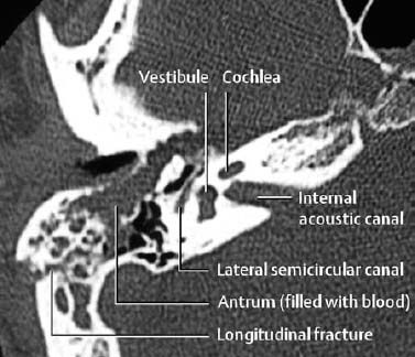
Fig. 1.78 Longitudinal fracture of the temporal bone as seen on axial CT.
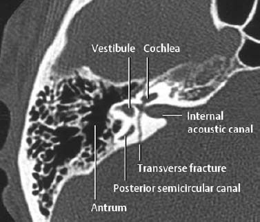
Fig. 1.79 Transverse fracture of the temporal bone on axial CT.
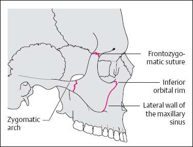
Fig. 1.80 Schematic diagram of the zygoma and the four typical fracture sites.
| 1. Localized fracture | |
| Solitary fracture: | Complex fracture: |
| Nasal bone (> 50%) | Zygomaticomaxillary complex (ZMC) |
| Zygomatic arch Isolated wall of the sinus cavity | Naso-ethmoidal, nasofrontal Blow-in, blow-out (orbit) |
| Mandible | Fronto-orbital |
| 2. Transfacial fracture | |
| Le Fort 1 | |
| Le Fort II | |
| Le Fort III | |
| Combinations |
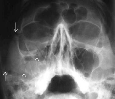
Fig. 1.81 Fracture of the right zygoma with a fracture line at all four typical sites (compare with (Fig. 1.80). Hemorrhage into the maxillary cavity with air fluid levels suggests osseous trauma, even without definite delineation of fractures.
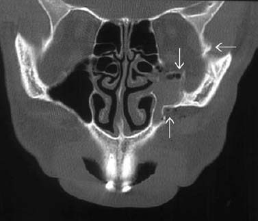
Fig. 1.82 Fracture of the zygoma with separation of the zygoma from its maxillary, frontal, and orbital connection (arrows).
Localized Fractures of the Facial Bones
Fracture of the Nasal Bones
This is the commonest localized facial fracture and the extent of injury depends on the direction and severity of the traumatic blow. The spectrum ranges from a widened nasofrontal suture and a simple nasal fracture to a comminuted fracture with involvement of the orbit and base of the frontal bone.
Fracture of the Zygoma
This is the second commonest facial fracture. The mechanically weakest point is the zygomatic arch. The most frequent manifestation is a depressed fracture with medial displacement of the fragments.
Clinically, the lateral facial structures are asymmetric, and involvement of the temporomandibular joint causes impaired movement of the mandible.
Fracture of the Zygomaticomaxillary Complex (ZMC)
Synonym: Tripod or quadruped fracture Four osseous sites are fractured, separating the zygoma from its temporal, frontal, and maxillary fixation (Figs. 1.80–1.82).
Blow-out Fracture
A sudden increase in intracranial pressure (e.g., blow with a fist, ball, or stick) causes the thin osseous walls (orbital floor, medial orbital wall) to fracture and the osseous fragments to be displaced into the maxillary sinus or ethmoid air cells (Fig. 1.83, 1.84).
Frequent complications of this injury are herniated or entrapped intraorbital fat or extraocular muscles, hemorrhage into the vitreous body, and traumatic cataract (Fig. 1.84).
The clinical findings include double vision, hematoma, enophthalmos, paresthesias (involvement of the infraorbital nerve), and eyelid edema.
 This fracture characteristically produces a ‘teardrop’ along the roof of the maxillary sinus (Fig. 1.83), an air-fluid level in the maxillary sinus (blood) and, possibly, periorbital soft-tissue swelling. Orbital emphysema can be an indirect sign of this injury. Fracture of the thick and relatively strong infraorbital rim is rare. A definitive evaluation of the fracture can be achieved by CT, which also reveals the extent of any possible herniation of fat and muscle into the maxillary sinus (Fig. 1.84).
Blow-in Fracture
This causes intraorbital displacement of osseous fragments and soft tissues.
Midfacial Fractures
The commonest cause of midfacial fractures is motor vehicle accidents. The Le Fort classification is used for midfacial fractures, which can occur in any combination and are frequently associated with other fractures (‘complex midfacial fractures’). One should, however, remember that midfacial fractures always include the pterygoid process (Fig. 1.85).
 Midfacial fractures are unstable and are characterized by involvement of the pterygoid process.
Le Fort I
This injury involves separation of the alveolar process from the maxilla, causing a’floating palate’. The basal aspects of all walls of the maxillary sinus are fractured.
Le Fort I fractures are best demonstrated by coronal CT (Fig. 1.86).
Le Fort II
This injury involves separation of a pyramidal fragment of the central portion of the face. The fracture line traverses the nasal base and the medial orbital wall bilaterally with extension to the orbital floor and infraorbital rim. The medial wall of the maxillary sinus is preserved (in contrast to the Le Fort I fracture, Fig. 1.86).
Complications: Damage to the infraorbital nerve in 80% of cases, entrapment of the extraocular inferior rectus muscle, damage to the nasolacrimal duct.
Le Fort III
This is complete separation of the facial bones from the skull. The fracture line traverses the nasal base, medial orbital wall and floor of the orbit bilaterally, and extends to the lateral orbital wall with an additional fracture of the zygomatic arch and pterygoid process.
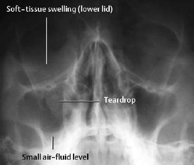
Fig. 1.83 Blow-out fracture of the orbit with the typical ‘teardrop’ soft-tissue density.
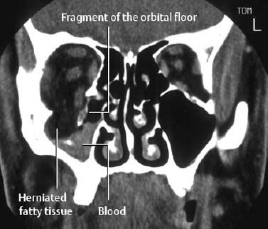
Fig. 1.84 Blow-out fracture of the orbit as seen on coronal CT. The herniation of intraorbital fat and inferior rectus muscle is clearly displayed.
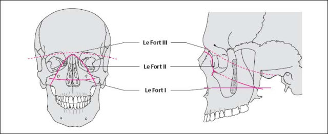
Fig. 1.85 Schematic diagram of the fracture lines of Le Fort fractures.
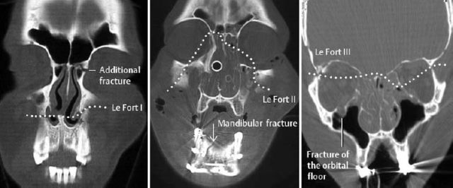
Fig. 1.86 Le Fort fractures I–III. coronal CT. These fractures are invariably associated with other facial bone injuries. A combination of the different Le Fort fracture types is common. The involvement of the left medial orbital wall of the Le Fort III fracture is best seen on more anterior sections.
Spine
Fractures, dislocations and soft-tissue injuries can affect the spine at any level. In the majority of cases, clinical and radiologic findings can readily establish the correct diagnosis. Insufficient experience, as well as inadequate image quality (mobile units, poor positioning of immobile patients), is responsible for the relatively high rate of missed vertebral injuries (approximately 25–50%). Improvement in detection can be expected from a better understanding of the different trauma patterns and pathogenic mechanisms and from familiarity with the radiographic approach.
Classification of Spinal Fractures
Spinal injuries can be categorized according to the traumatic forces that cause them:
- Compression,
- Flexion,
- Extension,
- Rotation,
- Translation.
Since the severity of the traumatic force determines the extent of the damage, the spectrum of damage varies from trivial soft-tissue lesions to severe osseous and ligamentous injury.
Distinguishing between stable and unstable injuries will be discussed at the end of the chapter.
 Conventional radiographs remain the best screening examination for vertebral trauma. The standard projections most suitable for the various anatomic regions are listed in Table 1.8. The lateral view is most important and should be obtained prior to moving the patient or taking the patient off the trauma board.
 CT has effectively replaced conventional tomography and is also superior to conventional radiography in diagnosing spinal injuries. CT provides excellent visualization of the bones and soft tissues and is capable of multiplanar image reconstruction. Its most important indication is assessing any involvement of the posterior border of fractured vertebral bodies (stability) and any cord compression by displaced fragments or hematomas.
 The advantage of MRI is its superb visualization of soft tissues, permitting delineation of diskoligamentous and cord injuries (edema, hematomyelia, transection).
Flexion Fractures
- Teardrop fracture: A tear of the anterior longitudinal ligament causes avulsion of a teardrop-shaped fragment at the anterior inferior end plate with dislocation of the affected vertebral body into the spinal canal. On the lateral view, the osseous fragment is smaller in height than in width, which is considered an (uncertain) criterion differentiating a flexion teardrop fracture from an extension teardrop fracture (see below). This fracture is most commonly seen in the lower cervical spine (in 70% at C5, Fig. 1.87). It is completely unstable and leads to vertebral dislocation with paraplegia in more than 80% of cases.
- Compression fracture: This a relatively common fracture of the anterior vertebral corner with wedging of the vertebral body. It is stable since the posterior aspects of the spine (including ligaments) remain intact.
- Burst fracture: This is a common fracture of the thoracolumbar transition characterized by anterior loss of height of the vertebral body and fragmentation of its posterior border. The posterior fragments of this comminuted fracture are often displaced into the spinal canal with a high incidence of associated neurologic complications. The resultant narrowed AP diameter of the spinal canal generally correlates with the severity of the neurologic symptoms (Fig. 1.88). The diagnostic evaluation (best in the acute setting by CT) must assess any narrowing of the spinal canal and associated soft-tissue changes (cord, disk, ligaments).
- Chance fracture or seat-belt injury: This is a flexion injury with the fulcrum in the region of the anterior abdominal wall. Severe abdominal injuries also occur in 15% of cases. It was once a common injury in motor vehicle accidents when only lap-type seat belts were used; it has become relatively rare today following the introduction of the shoulder strap. Radiographically, a horizontal fracture is seen through the vertebral body (predominantly of L1–L3), with involvement of both pedicles, the arch, and the spinous process (Fig. 1.89).
- Clay shoveler’s fracture: This fracture, originally described in clay or coal shovelers, represents an avulsion fracture of the spinous process at the insertion of the supraspinous ligament (C6–T3). This injury is stable.
- Anterior subluxation and dislocation: The segmental rupture of the posterior ligament causes an anterior angulation of a vertebral body relative to the subjacent vertebral body with fanning of the spinous processes, incomplete articulation of the facet joints, and possible anterior displacement of the subluxated vertebra Fig. 1.90). The stability is determined by the extent of angulation and translation. The most important diagnostic criterion is the hypermobility of one segment observed in an otherwise hypomobile spine. A subtle anterior subluxation cannot be diagnosed by conventional radiography and, if clinically suspected, requires an MRI.
- Bilateral facet joint dislocation (blockade): This injury complex is predominantly seen in the lower cervical spine. Caused by severe distraction of the dorsal ligaments with resultant anterior dislocation of the more cephalad vertebra, it leads to spinal canal stenosis and is often associated with neurologic symptoms (Fig. 1.91).
| Projection | Anatomic structure |
|---|---|
| AP | Vertebral body, pedicle, spinous process, intervertebral disk space, paravertebral space |
| Dens AP (open mouth odontoid view) | Atlas, axis (including dens), atlantoaxial articulation |
| Lateral | Vertebral body (height, posterior border), intervertebral space, prevertebral soft tissues |
| Swimmer’s view | C5–T2 |
| Oblique views | Facet joints, spondylolysis |
| Functional views | Instability (only with cooperative patients and normal initial views) |
| Tomography | Dens, cervicothoracic and thoracolumbar transition |
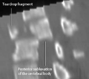
Fig. 1.87 Flexion distraction injury (teardrop fracture). Reformatted sagittal CT image shows marked narrowing of the spinal canal by the retropulsed vertebral body fragment.
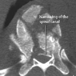
Fig. 1.88 Burst fracture (T11) with the posterior fragment displaced into the spinal canal.
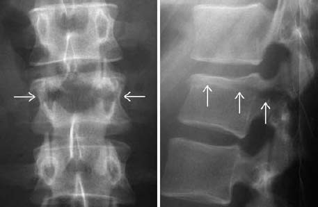
Fig. 1.89 Chance fracture. The L2 vertebral body is divided by a horizontal fracture through the vertebral body and both arches.
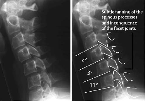
Fig. 1.90 Segmental hypermobility of C5–6. The 11-degree angulation by itself is not pathologic, but the associated severe segmental kyphosis is. Such a finding:
- can represent a normal variant,
- can be caused by muscle spasm following whiplash injury,
- but is strongly suspicious for an anterior subluxation.
A reliable differentiation is not possible with conventional radiography.
Radiographic Hints: Flexion Fractures
- Interrupted posterior cervical line: displacement, rotation, angulation, absence, and doubling are abnormal,
- Increased interpedicular width on the AP view (secondary to fracture of the lamina),
- Forward displacement,
- Segmental hypermobility,
- Subluxation or dislocation of the facet joints,
- Narrowed intervertebral disk space – usually above the fractured vertebra.
Extension Fractures
- Anterior avulsion fracture (also referred to as ‘extension teardrop fracture’): The anterior longitudinal ligament avulses a fragment from the anteroinferior or superoanterior edge of the vertebral end plate (Fig. 1.92). On the lateral view, the height of the avulsed fragment is usually equal to or larger than its width. In contrast to the flexion fracture, this extension fracture generally affects the upper cervical spine (most frequently at C2) and is stable on flexion. Neurologic deficits are rare.
- Hangman’s (‘Hangee’s’) fracture
Related posts:

Stay updated, free articles. Join our Telegram channel
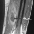
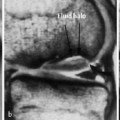
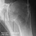
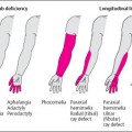


Full access? Get Clinical Tree


