Treatment Delivery Systems
CHAPTER 5.A PASSIVE BEAM SCATTERING
Bernard Gottschalk
The particle beam transported from the accelerator to the treatment area is as small as possible to reduce the cost of the beam transport. Just before the patient, the beam is spread out to cover the field cross section and extent in depth of the planning target volume (PTV) in a section of beam line called the nozzle, which is analogous to the treatment head in photon LINACs. This can be done in two basic ways. In “scanning,” described later, deflecting magnets are used to scan the beam over the PTV.
The “scattering” or “passive” technique uses arrangements of scatterers and degraders. Passive systems are relatively simple and achieve adequate conformation of the dose to the PTV. Scanning systems can do better in principle but are more complicated. Passive systems currently dominate clinical use but the trend is toward scanning.
Our overview of passive techniques will be nonmathematical. Passive systems can be designed from first principles, and little or no empirical adjustment is needed. It is not necessary to use trial and error or Monte Carlo simulations. Computer programs are available to help. The reader wishing to go beyond this short review should consult Gottschalk.1
BASIC PHYSICS
For a review of how protons, or charged particles in general, interact with matter, see Chapters 2 and 8. The reader is also directed to Berger et al.,2 for additional discussion of this topic.
Stopping
Protons that enter human tissue, or a water tank as substitute, slow down and eventually stop. The “Bethe-Bloch” theory of this slowing and stopping process was developed in the 1930s and refined subsequently.2 It predicts the rate of slowing down, or energy loss, as a function of the incident particle type and energy and the composition of the stopping material. By a simple extension, it therefore predicts the mean range of a given beam in a given material to an accuracy of 1% to 2%. For example, 160-MeV protons (whose speed is approximately half the speed of light) have a mean range of approximately 17 cm in water. These protons do not, however, all stop at exactly 17 cm, because stopping is the statistical outcome of thousands of collisions with atomic electrons. The approximately 1% fluctuation in the range of any given proton is called range straggling.
Protons lose energy faster as they slow down. The dose is greatest just before they stop. This leads to the Bragg peak in the depth-dose distribution, arguably the protons most important characteristic for radiation therapy. The peak becomes sharper, and the peak/entrance dose ratio larger, as incident proton energy decreases.
Scattering
If protons enter the water tank in exactly the same direction we will find them, after a few centimeters, going in slightly different directions by a degree or so. This gradual
spread in their angular distribution is known as multiple Coulomb scattering because it arises from thousands of small electrostatic deflections by atomic nuclei. The accepted theory was published by Molière in 1947.3 It predicts the characteristic multiple scattering angle as a function of the incident particle type and energy and the composition of the scattering material, and holds even if the particle loses nearly all its energy. It has been tested experimentally to a few percent.4
spread in their angular distribution is known as multiple Coulomb scattering because it arises from thousands of small electrostatic deflections by atomic nuclei. The accepted theory was published by Molière in 1947.3 It predicts the characteristic multiple scattering angle as a function of the incident particle type and energy and the composition of the scattering material, and holds even if the particle loses nearly all its energy. It has been tested experimentally to a few percent.4
The distribution of angles after multiple scattering is nearly a Gaussian, the bell-shaped curve familiar from statistics. What Molière’s theory allows us to calculate for any given case is the width of that Gaussian. The theory also predicts a large departure from the Gaussian shape for large angles, but that represents so few protons that we can ignore it in designing passive systems
Like stopping, scattering in a given material increases as the proton slows down, but according to a different mathematic formula. The net scattering when a proton passes through a thin sheet of material is roughly proportional to the square-root of the thickness of the sheet, whereas the net energy loss is directly proportional to the thickness.
High-Z versus Low-Z Materials
Because stopping arises from interactions with atomic electrons, whereas scattering arises from nuclei, they depend differently on the target material. In a relative sense, materials with low Z (atomic number) are more effective in slowing protons down, whereas materials with high Z, scatter protons much more strongly. If we want to scatter a beam with minimum energy loss, we should use a high-Z material such as lead. To decrease proton energy with minimum scatter, we should use a low-Z material such as plastic or beryllium. By combining high-Z and low-Z materials in a “binary degrader” we can control both energy loss and scattering.
Nuclear Reactions
Besides stopping and scattering, protons can collide headon with an atomic nucleus. The resulting collision yields an excited residual nucleus, secondary protons and neutrons and (less frequently) heavy charged fragments such as α particles. Unlike stopping and scattering, the detailed description of all this is exceedingly complicated. Nuclear reactions are rare; approximately 20% of 160-MeV protons suffer one, compared to the thousands of other interactions, before they stop in water.
Fortunately for us, the decay products have such short ranges (they need to share the kinetic energy of the original proton) and make such large angles with the beam direction that they rarely reach the target region. Therefore, we can ignore nuclear reactions except for the diminution of the primary beam. They do not affect the target dose distribution, only its absolute value.
SINGLE SCATTERING
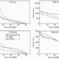
Figure 5A.1 shows the simplest useful passive scheme. We will use numbers typical of a short-throw (the distance between the first scatterer and the middle of the target) neurosurgery beam. A single scatterer (lead, because we want to maximize scattering and minimize energy loss) is placed 100 cm upstream of the target volume. If we want the dose uniform to ±2.5% out to a radius of 1 cm, we need to create a Gaussian wide enough so it falls to 95% at 1 cm. For 160-MeV incident protons, 0.25 cm of lead will suffice. All of this can be calculated—we do not need trial and error—but these calculations are not within the scope of this discussion.
This trivial system has a number of weaknesses. First, its efficiency, the fraction of protons within the useful ±2.5% dose region, is only 5%1 and the transverse dose distribution is not exactly flat even over this small region. Second, the protons lose 7.5 MeV or 1.4 cm water equivalent penetration in passing through the lead. Both the efficiency and energy loss can be improved by using double scattering (see following text). Finally, the depth-dose distribution is a Bragg peak with a width of approximately 0.6 cm at the 90% level. It is only suitable
for targets, such as the pituitary gland, with very little extent in depth.
for targets, such as the pituitary gland, with very little extent in depth.
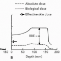
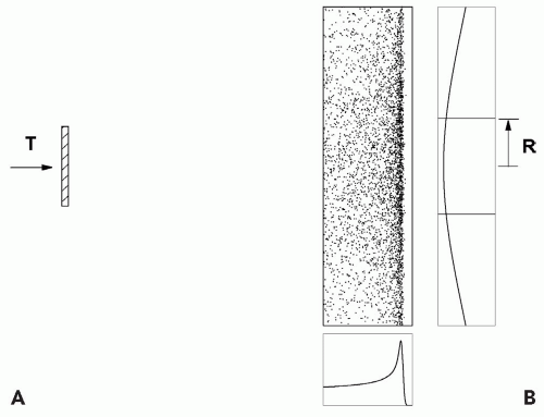 Figure 5A.1 Single scattering example (dimensions not to scale). A narrow proton beam of kinetic energy T is incident on a slab of material (A). The scattered proton intensity has a Gaussian distribution centered on the beam axis as indicated in the intensity profile (B). The intensity profile has a useful radius R defined by the extent of the Gaussian profile that drops to 5% of the maximum intensity, thereby producing a useful clinical beam profile with ±2.5% uniformity. The proton beam of kinetic energy T produces a pristine Bragg peak whose dose profile is shown on the bottom right. The distribution of dots is the density of deposited dose as a function of radius. |
RANGE MODULATION
Upstream
If the target has greater extent in depth, we need a range modulator to spread out the Bragg peak in depth in addition to a scatterer. The range modulator is typically a propeller-shaped object which rotates so as to put successively thicker layers of plastic into the beam. Each layer pulls back the Bragg peak in the target by an amount equal to the water equivalent thickness of the plastic. The thickness of each layer and the relative time it spends in the beam are carefully calculated so that the resulting spread-out Bragg peak (SOBP) will be flat. The arrangement is shown schematically in Figure 5A.2, with one extra feature. Suppose the distal edge of the PTV is shallower than the range of the beam after scattering. We can move the entire dose distribution forward by means of an additional piece of plastic, a “range shifter”.2
We now have three quantities characterizing the dose distribution: the useful radius r, depth d, and modulation m. These must be such as to cover the PTV.
If the scattering in the combined range shifter and modulator is insufficient to achieve lateral conformation to the PTV, we can add some lead or brass and compensate by removing some plastic. Usually this computation is different for each modulator step. It yields an energy compensated range modulator.
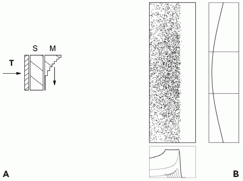 Figure 5A.2 Single scattering (not to scale) with range modulator (M) and extra scatterer. The rotating range modulator shifts the monoenergetic pristine peak to lower ranges and creates the characteristic spread-out Bragg peak (SOBP, lower figure). In addition, a constant thickness range shifter (S) can be used to achieve a global adjustment of the SOBP depth to match the depth of the target volume. |
Downstream
Figure 5A.2 shows an upstream modulator, so called because it also serves as part of the scatterer. The modulator’s scattering, if it cannot be compensated, must be taken into account when designing the dwell-time of each step. Historically, the range modulators were placed downstream much nearer the patient.5 Scattering in the modulator can then be ignored because of the small distance between it and the patient. Not only is the modulator easier to design, but the same modulator can be reused with various scattering systems.
An obvious disadvantage is that, being near the patient, the range modulator must be large enough to cover the entire treatment field, not merely the incident beam. That makes it difficult to change remotely and unsuitable for a gantry. Less obviously, a downstream modulator diffuses the effective proton source and makes the edges of the dose distribution less sharp as discussed in the following text. Figure 5A.3 shows an upstream and a downstream range modulator.
Lamination
Range modulation is accomplished by putting extra material into the beam in a carefully programmed way. Instead of prefabricating the “propellers” discussed in the preceding text, one could simply insert individual constant thickness degraders and scatterers into the beam under the control of a computer. A popular arrangement employs plastic degraders and lead scatterers in binary sequences of thickness, so that any desired combination can be made up. Finally, we can use linear or helical wedges, or an adjustable water column.
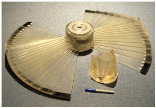 Figure 5A.3 Two sample range modulators, upstream (small) and downstream. Both are characterized by a “staircase” structure to achieve the differential pullback of the pristine proton beam and variable widths of the “stair-steps” to achieve differential weighting of the shifted pristine peak contribution to the spread-out Bragg peak (SOBP). The downstream range modulator is large to cover the clinical area of the scattered proton beam at the downstream position. |
All of these methods have been used. The SOBP is created step-wise in a process called lamination. A single set of hardware can produce any desired SOBP, eliminating the need for a large assortment of modulators. The mechanics and software are, however, more complicated. Because of the changeover time between degraders, lamination delivers the SOBP sequentially as a function of range and only once or twice per treatment session. This increases sensitivity to organ motion but only along the depth dimension as the lateral dimension is produced by scattering over the entire treatment field. By contrast, a spinning upstream modulator can easily paint the entire SOBP ten times per second.
Beam Gating and Beam Current Modulation
If we use rotating modulators, how many do we need to cover all clinical requirements? A given modulator only works well over a limited incident energy span, and we need one for each SOBP modulation width. At first glance we might need hundreds of modulators!
The number can be greatly reduced by noting that a modulator properly designed for full modulation (m = d) can yield any lesser m if the beam is turned off during part of each revolution so as to eliminate the appropriate number of proximal dose layers that contribute dose below m. This method has two costs. First, the average dose rate is less than it would be with a purpose-built modulator because the beam is turned off part of the time. Second, the system is more complex and requires more checks. The delivery of the SOBP depends critically on synchronization of the beam current with the modulator.
A further reduction in the number of modulators can be obtained by varying the beam current during the modulator cycle. The built-in dwell times, defined by the angular width of the modulator steps, are only the first approximation to the desired exposure for each step, the rest being achieved by beam current modulation. The cost, as ever, is yet more engineering and more checks. In particular, the cyclotron output current detector must be very linear and stable.
Beam current modulation with a dynamic range from zero to full beam current provides full dynamic control of the creation of an SOBP depth-dose profile almost independent of a particular range modulator. This feature exists at the Francis H. Burr Proton Therapy Center (FHBPTC), formerly the Northeast Proton Therapy Center, where just four modulators cover all clinical requirements in the second gantry room.
DOUBLE SCATTERING
Double scattering was developed to reduce energy loss and improve efficiency, making large fields practical. The first scatterer is uniform. It produces a Gaussian beam profile on the second scatterer, which must be nonuniform in some way3, modifying the Gaussian so as to produce a flat or nearly flat dose distribution at the patient.
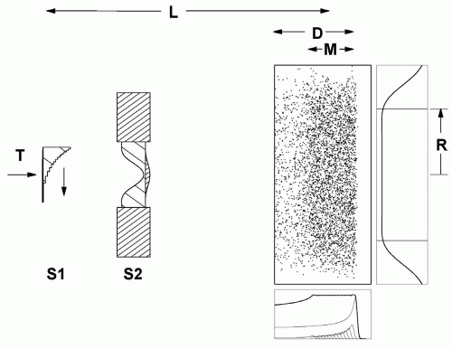 Figure 5A.4 Double scattering example (not to scale) with an upstream range modulator. The range modulator (S1) serves both as the range shifter and as the first scatterer. The range modulator is typically constructed from two materials to achieve constant scattering as a function of wheel rotation angle. The second scatterer (S2) also contains two materials to achieve differential scattering across the profile which results in the optimized profile of useful radius R. The beam line parameters are the kinetic energy T and the source to axis distance L. The prescription parameters are the prescription depth (range) D and modulation width M. |
The first such scheme6 used a flat second scatterer partly blocked by a cylindrical plug or occluding ring. The method preferred currently contours the second scatterer7,8 so that central protons are more strongly scattered, flattening the field at the patient (see Fig. 5A.4). The contoured scatterer, by itself, causes central protons to lose more energy than protons at larger radii, so we add an appropriately shaped plastic energy compensator. In a typical implementation (FHBPTC gantry room, 250 cm throw and 100- to 230-MeV protons) the efficiency is approximately 45%. The dual ring method9 is a kind of compensated contoured scatterer, with a less uniform dose.
A drawback of double scattering is an increased sensitivity to beam steering. If the beam is off center by as little as a millimeter on the second scatterer, the flat dose distribution shown in Figure 5A.4 will tilt. This easily happens in a proton gantry because of mechanical and magnet errors. The beam steering magnets at the FHBPTC use a feedback system which senses the distortion in the beam profile downstream of the second scatterer and corrects the steering.
PATIENT-SPECIFIC HARDWARE
The methods described so far fill a cylindrical volume (more accurately, a truncated cone) with nearly uniform dose over the modulation width m in a water tank. Real PTVs are not cylindrical, and real patients are not uniform in density. Better conformation of the dose to the target volume is obtained with patient field-specific hardware, fabricated automatically by machine tools using computer files prepared by the treatment planning program.10 Absence of patient-specific hardware is a frequently asserted goal of magnetic scanning, but it is far from clear that the same degree of dose conformation can be had, particularly without an aperture for shallow targets.
Aperture
The patient aperture (see Fig. 5A.5) is a brass beamstop with a hole shaped to the outer projection of the target in the beam’s eye view. This, as in photon radiotherapy, eliminates protons heading outside the PTV. It is impractical to block all protons in this way. That would require a wall of brass which could not be brought very near the patient (see the section “Lateral and Distal Dose Falloff” in the following text). Therefore the snout (see Fig. 5A.6) not only supports the aperture and range compensator near the patient, but is carefully designed to block unwanted protons, as are other nozzle components further upstream.
Range Compensator
The range compensator (Fig. 5A.5) is a plastic block with material cut away in a complex shape. It is carefully aligned with the aperture and the patient’s PTV and tailors the dose in depth by shifting more or less proton range depending on what part of the PTV, and upstream tissues, a particular proton ray is aimed at. In this way, it can compensate for three effects simultaneously: patient external variation, the distal PTV surfaces (with respect to the beam axis), and tissue heterogeneities in the patient. Compensators may be designed for diverse clinical goals: Guaranteeing target coverage in the face of alignment errors, patient and internal organ motion, and assuring that neighboring critical structures are spared.11
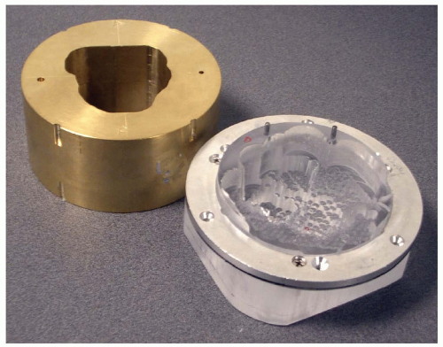 Figure 5A.5 Patient-specific brass aperture to achieve lateral field confirmation to the target volume beam’s eye view (BEV) and a polymethyl methacrylate (PMMA) range compensator to achieve distal confirmation. |
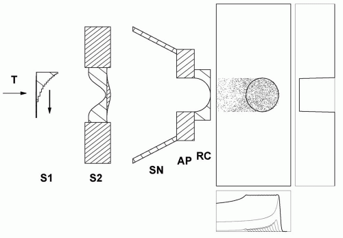 Figure 5A.6 Double scattering system (Fig. 5A.4) with a beam line snout SN which shields scattered protons and permits the mounting of patient-specific apertures AP and range compensators RC. The example illustrates the effect of the range compensator in water and indicates the sharp lateral falloff achieved by the aperture. |
Figure 5A.6 shows the combined effect of a very simple aperture and range compensator. Note the “ears” of unwanted high dose proximal to the target. These are a consequence of constant range modulation over the field. Magnetic scanning can eliminate this and similar problems.
LATERAL AND DISTAL DOSE FALLOFF
Sharp dose distributions are the raison d’etre of proton radiation therapy, and poor nozzle design can produce poor dose gradients at the PTV boundary.4
The final aperture, near the patient, casts a sharp shadow. Any additional material, such as a second scatterer, introduces additional scattering and acts as a diffusing screen, causing the shadow to be less sharp. Still worse is a third object, such as a modulator or range shifter, near the patient. The general rule is that the perturbing effect of any beam-modifying material is worse, the further downstream
it is located.12 It is for this reason that a single scattering system with upstream modulator produces the sharpest dose. If a second scatterer must be used, to irradiate a large field or conserve energy, it should be as far upstream as practical.
it is located.12 It is for this reason that a single scattering system with upstream modulator produces the sharpest dose. If a second scatterer must be used, to irradiate a large field or conserve energy, it should be as far upstream as practical.
Further scattering occurs in the patient. Therefore the dose gradient will be poor for deep targets no matter how good the nozzle design, which is also the case for scanned beams.
For a given design, the lateral dose falloff will be worse, the larger the air gap between the final aperture and the patient. The need to keep this gap as small as possible makes it desirable to have snouts (Fig. 5A.6) of graduated sizes to minimize mechanical interference with the patient. It also means that variable collimators are less useful than in photon therapy, because they are large devices hard to position near the patient. A large air gap spoils not only the dose edges but also the accuracy with which the range compensator deals with tissue inhomogeneities.13
The distal dose falloff is determined by the shape of the Bragg peak. Unlike lateral falloff, the distal falloff does not intrinsically increase with depth in the patient. However, it does depend on range straggling and therefore increases with energy. Consequently, if one treats a lesion with a beam delivered into the nozzle of sufficient energy to reach the distal edge of the PTV yields a sharper distal falloff compared to a beam of higher energy degraded in the nozzle. Arduini et al.,14 discuss lateral and distal falloff quantitatively. In many cases, the clinical need for sharp distal falloff is unclear, especially when considering the intrinsic uncertainties in the range determination in patient.
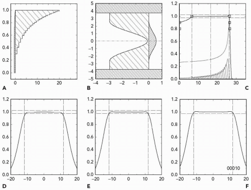 Figure 5A.7 Example NEU output example with schematic picture of the range modulator (A), cross section of compensated contoured second scatterer (B), depth-dose distribution produced by the range modulator (C), and open field transverse scans at three depths (D to F). |
DESIGN PROGRAMS
The physics of stopping and scattering is well understood, and nuclear interactions can be included by using measured Bragg peaks. Therefore, passive scattering systems can be accurately designed to meet clinical specifications. The author’s computer program NEU, for instance, designs an upstream modulator and second scatterer to use given machine parameters (energy and throw) and produce the desired field radius, depth and modulation. It also estimates the dose rate for a given incident proton current. Figure 5A.7 is a typical NEU output.15
CLINICAL LIMITS
Practical materials have their limitations. Lead, for instance, is good for scattering but also causes some energy loss,
whereas plastic or beryllium are good energy degraders but also cause some scattering. Therefore, given energy and throw, passive scattering can only achieve certain combinations of radius, depth, and modulation. The limits are best summarized on a plot of radius versus depth. Figure 5A.8 is an example. It shows what can be done with a fixed-energy machine at 230 MeV and a throw of 250 cm. If, as at FHBPTC, the energy is continuously variable up to the maximum, an analogous diagram, with a different characteristic depth, applies at each energy.
whereas plastic or beryllium are good energy degraders but also cause some scattering. Therefore, given energy and throw, passive scattering can only achieve certain combinations of radius, depth, and modulation. The limits are best summarized on a plot of radius versus depth. Figure 5A.8 is an example. It shows what can be done with a fixed-energy machine at 230 MeV and a throw of 250 cm. If, as at FHBPTC, the energy is continuously variable up to the maximum, an analogous diagram, with a different characteristic depth, applies at each energy.
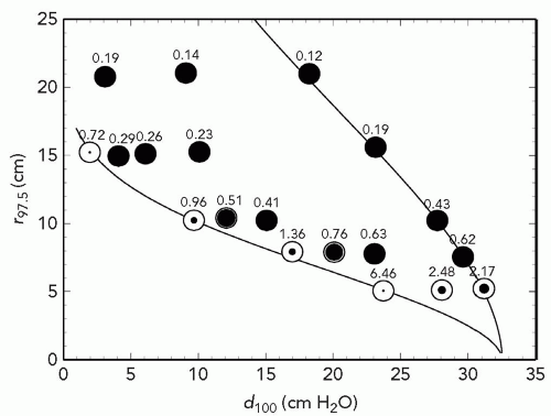 Figure 5A.8 Prescription parameters obtainable by double scattering 230-MeV protons with a throw (S1 to center of spread-out Bragg peak [SOBP]) of 250 cm and S2 placed at 50 cm. The abscissa is d100, the treatment depth at the 100% dose level. The ordinate is r97.5, the radius at which dose falls to 97.5%. The right-hand line is the maximum possible r(d) whereas the left-hand line is the minimum. Symbols represent test runs with program NEU. The degree of filling represents the maximum obtainable modulation m100 relative to d100. All black means that any modulation 0 < m100 < d100 can be obtained. The numbers are dose rate (Gy per minute) assuming a proton current of 1 nA incident on S1.
Related posts:Stay updated, free articles. Join our Telegram channel
Full access? Get Clinical Tree
 Get Clinical Tree app for offline access

|