Hans-Marc J. Siebelink, Jos J.M. Westenberg, Lucia J.M. Kroft, Albert de Roos
Cardiac Anatomy and Imaging Techniques
Knowledge of the cardiac anatomy is essential for identifying and understanding cardiovascular disease in patients and is therefore important in clinical practice. To date, various imaging techniques such as conventional chest radiography, cardiac magnetic resonance (CMR) imaging, computed tomography (CT) and echocardiography are all used to assess aspects of cardiac and vascular anatomy. This chapter contains an overview of the techniques used and provides examples of the anatomy identified with these techniques.
Normal Chest Radiography
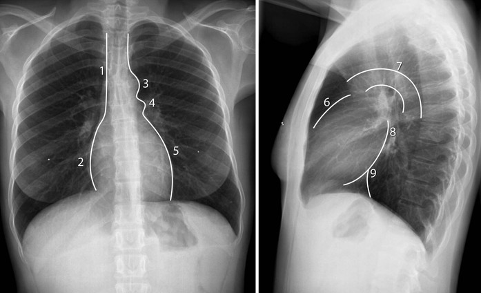
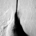
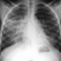
Postero-anterior and lateral chest radiographs are commonly obtained in patients with cardiovascular disease. The chest radiograph provides an impression on the size of cardiovascular structures and the lung parenchyma. Specific cardiac chambers and large vessel anatomy can be recognised from chest radiography. Evaluation of the lung parenchyma and lung vasculature is helpful for assessing and grading heart failure. Valvular calcifications may be recognised as a clue for specific valvular disease. Figure 19-1 illustrates the normal chest radiograph, noting normal cardiovascular structures.
Cardiac Magnetic Resonance
An advantage of choosing magnetic resonance for cardiac imaging is the free choice in obtaining imaging planes of cardiovascular anatomy in any arbitrary view, since this technique is not hampered by the limited availability of acoustic windows, as with ultrasound. This benefit is especially advantageous when imaging the morphology of the right ventricle (RV), which is excellently delineated by CMR, whereas in echocardiography, the assessment of RV geometry and function is challenging because of the particular crescent shape of the right ventricle wrapping around the left ventricle.1 Furthermore, the unrestricted field of view of CMR allows superior visualisation of extracardiac and large vessel anatomy.
Single-plane two-dimensional (2-D) or multiple-plane 2-D or three-dimensional (3-D) imaging is possible with CMR. Dynamic functional information can be obtained by synchronising image acquisition to the RR interval of the electrocardiogram, using either prospective triggering or retrospective gating.2 With prospective triggering, the operator needs to set the expected heart rate before the acquisition and triggering will be performed according to this defined heart rate. With retrospective gating, imaging is performed continuously and the electrocardiogram (ECG) signal is stored additionally. In retrospect, image reconstruction is synchronised to the stored ECG, providing time-resolved imaging in multiple phases of the cardiac cycle, which can be presented in cine mode.
Imaging planes in CMR are usually obtained in the orientation to the axes of the heart, or oriented to the major axes of the body. Therefore, the standard CMR planes of the heart are comparable to the standard cardiac views, well-known and established in other non-invasive imaging modalities such as echocardiography, cardiac CT, X-ray left ventricle angiography and nuclear medicine techniques.
The choice for a specific CMR protocol is mainly determined by the clinical questions that need to be answered. Standardised nomenclature for cross-sectional anatomy has been described,3 facilitating comparison between different techniques and proper communication between imaging specialists.
Another important issue in clinical CMR imaging is the ability of the patient to collaborate during the examination and to perform breath-holding repeatedly and consistently. If a patient is capable of performing breath-holding, successive imaging planes are obtained with accelerated imaging, with the patient usually performing breath-holding in end expiration, as the anatomical level may be more reproducible than planes which are examined in inspiration.4
CMR techniques for anatomical evaluation include bright-blood and black-blood imaging, which essentially determines the contrast between myocardium and the intracardiac blood pool. For the assessment of left and right ventricular function, fast-gradient echo sequences are usually performed in combination with steady-state free-precession (SSFP) technique (balanced-TFE, True-FISP, Fiesta) for optimal contrast. On these bright-blood images, the blood pool is presented with bright signal, whereas the myocardium is represented dark with low signal. This results in an excellent definition of the left ventricular endocardial and epicardial borders, which is required for accurate image segmentation during cardiac volume and function quantification. Typically, SSFP images should be acquired with slice thickness of 6–8 mm and temporal resolution less than 45 ms to obtain optimal accuracy in ventricular function assessment.5,6
Additionally, cardiac morphology can be evaluated by double-inversion black-blood spin-echo sequences with fat suppression, providing gated, static images of the heart with high spatial resolution (optimally, in-plane acquired resolution of less than 2 × 2 mm2 and slice thickness of 5–8 mm) in the orientation of the heart or the patient’s body axes. Multiple other MRI techniques are available for tissue characterisation (e.g. T2-weighted sequences, delayed gadolinium-based contrast enhancement), extending the capabilities of CMR beyond anatomical and functional evaluation of the cardiovascular system.
Cardiac Axis Imaging Planes
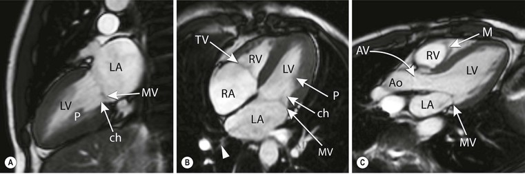
To acquire imaging planes in the direction of the cardiac axes, SSFP scout views are used for planning. If available, free-breathing images obtained during real-time imaging can be used instead. Perpendicular to an anatomical transverse image, displaying the heart’s four chambers, an acquisition plane is chosen through the middle of the atrioventricular junction at the level of the mitral valve and running through the apex (Figs. 19-2A, B). This plane is the so-called vertical long-axis (VLA) plane (Fig. 19-2C). On this VLA view, a plane is defined intersecting the apex and the middle of the mitral valve, resulting in the horizontal long-axis (HLA) view (Fig. 19-2D). This HLA view is almost comparable to the four-chamber view; however, often only a part of the left ventricular outflow tract is visualised in this HLA view. On the acquired HLA plane, the short-axis views (Figs. 19-2E, F) covering the entire left ventricle are planned parallel to the ring of the mitral valve and perpendicular to the line intersecting the apex.
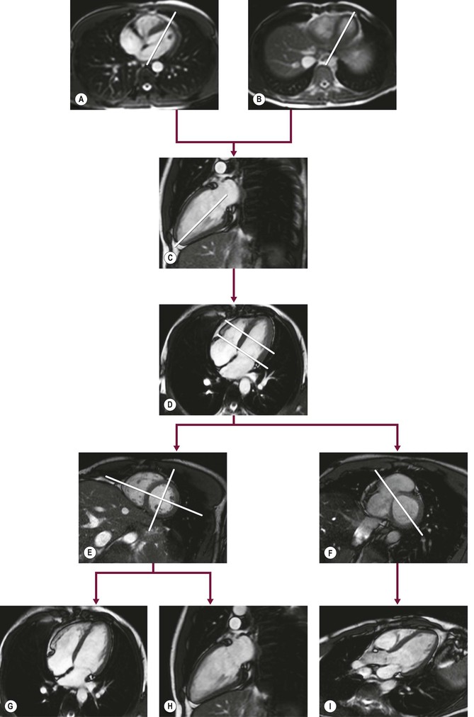
For reproducibility and comparison purposes, the true two- and four-chamber views can still be obtained (Figs. 19-2G, H). The two-chamber view is planned perpendicular to the anterior and inferior wall of the left ventricle through the centre of the left ventricular cavity on a mid-ventricular short-axis (SA) image intersecting the apex. On the two-chamber view the apex, anterior and inferior wall of the left ventricle, the mitral valve and left atrium can be evaluated. The four-chamber view is planned also on a mid-ventricular SA image by a plane through the centre of the left ventricular cavity and the acute margin of the right ventricle, also intersecting the apex (Fig. 19-2E). The four-chamber view depicts the interventricular septum, the lateral wall of the left ventricle, the free wall of the right ventricle, left and right atrium as well as the interatrial septum and both the mitral and tricuspid valves.
Routinely, the three-chamber or so-called left ventricular outflow tract (Fig. 19-2I) view is planned on a basal SA plane (Fig. 19-2F). This plane also intersects the apex. The left ventricular outflow tract view depicts the apex, the anteroseptal interventricular wall, the left ventricular outflow tract, the inferolateral wall, as the aortic and mitral valve, respectively.
The standard SSFP cine CMR protocol for assessing left ventricular function should include the two-, four- and three-chamber views in combination with SA images covering the entire left ventricle, resulting in images covering all described 17 left ventricular segments in two directions.3
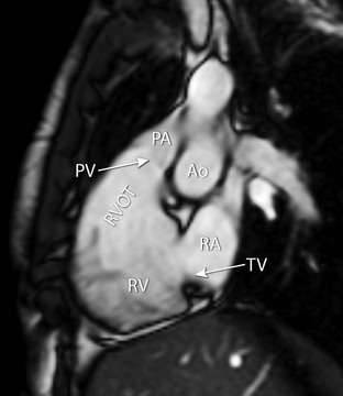
Additionally, the right ventricular outflow tract can be obtained (Fig. 19-3). This view can be planned on a coronal image, depicting the outflow tract of the right ventricle. Alternatively, an optimised view of the right ventricular outflow tract view can be obtained from a plane outlining the tricuspid valve plane and the outflow tract. On this plane the outflow tract, pulmonary valve, tricuspid valve and the basal (diaphragmatic) part of the right ventricular wall are all visualised.
Body Axes Imaging Planes
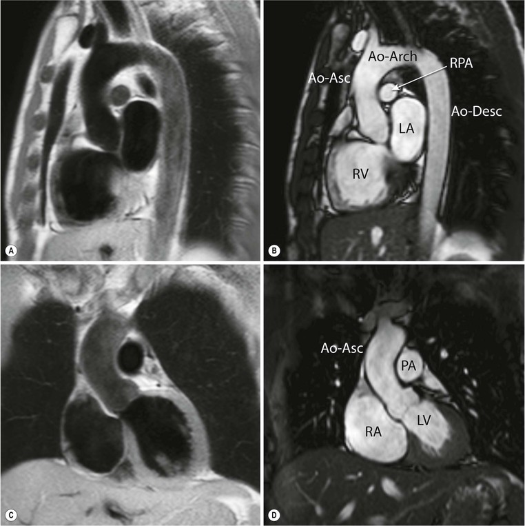
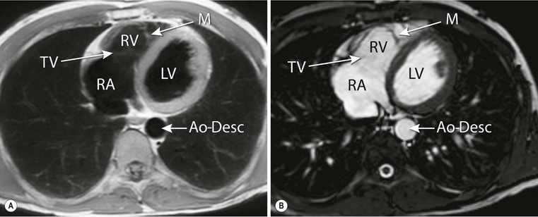
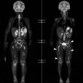
For the evaluation of cardiac morphology, the pericardium, the great thoracic vessels and (para-) cardiac masses, imaging planes oriented to the main body axes are obtained. Also, the transverse (or axial), coronal (frontal) and sagittal planes are well known to clinicians, as these anatomical orientations are similar to clinical (cardiac) CT. Black- and bright-blood sequence approaches (Fig. 19-4) can be used in optimally adjusted planes to answer specific clinical questions. Black-blood images provide only static information in a single phase and are not suitable for quantification of left or right ventricular dimensions. For this analysis, SSFP multi-phase images with appropriate temporal resolution are necessary.
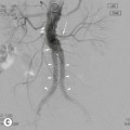
Transversely oriented planes (Fig. 19-5) are especially useful for the evaluation of thoracic vascular structures as the ascending and descending thoracic aorta, the superior and inferior vena cava, the pulmonary trunk and right and left pulmonary artery. The right and left pulmonary veins entering the left atrium are also well depicted. Images in transverse orientation through the heart allow the evaluation of morphology of the ventricles and atria. Also the right ventricular free wall, the right ventricular outflow tract, the pericardium and mediastinum are well depicted. It has been suggested that right ventricular volume and function quantification by planimetry can be performed more accurately on transversely oriented images instead of SA images.7
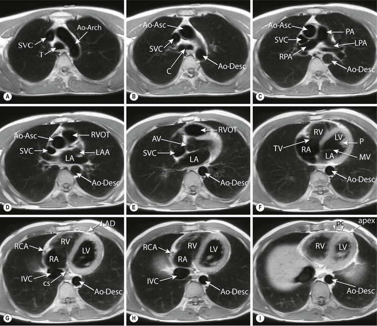
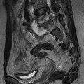
Coronal or frontal anatomical views can be instructive for analysing the connection between the heart and the great vessels. An advantage of the frontal view is the similarity to the well-known anatomy from chest radiography. On sagittal images, the right ventricular outflow tract in relation to the pulmonary valve is well outlined and the connection of the right atrium with the superior and inferior vena cava can be studied.
Normal Anatomy on CMR Images
CMR images present distinct anatomical features of both atria and ventricles. For evaluating anatomy, either cardiac axes (Fig. 19-6) or body axes imaging planes (Figs. 19-4 and 19-5) can be chosen. The pericardial sac encloses the heart and the roots of the great vessels. The pericardial cavity is outlined by the parietal and visceral layer of the inner pericardium. Normal pericardium has a longer T1 than fat tissue, and therefore presents with low signal intensity on T1-weighted MR images, and can be well visualised due to the surrounding epicardial and pericardial fat. Normally, the thickness of the pericardium measures less than 4 mm on CMR images.
In normal cardiac anatomy, the right atrium can be recognised by identifying the corresponding broad-based triangular appendage. At the base, the tricuspid valve, positioned between the right atrium and the right ventricle, is located closer to the apex compared to the mitral valve.
The right atrium receives venous blood from the superior and inferior vena cava, and the coronary sinus. The coronary sinus enters the right atrium in the posterior atrioventricular groove. The appendage of the morphological left atrium has a narrow attachment to the atrium and is more tubular shaped. Characteristically, the left atrium receives in total four pulmonary veins, two on either side, although several variations of this occur. To date, imaging the venous anatomy of the heart is becoming more relevant. For example, during pre-ablation work-up for supraventricular arrhythmias the clinician needs to be informed about the exact anatomy of the left atrial morphology and number of the pulmonary ostia, as the left atrium and pulmonary veins are used to guide the interventional procedure.8,9 The interatrial septum separates the two atria. As part of the interatrial septum, the fossa ovalis is very thin and can hardly be depicted on CMR images due to the limited spatial acquisition resolution.
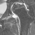
The right ventricle is normally triangular in shape and anteriorly located relative to the left ventricle, directly behind the sternum. Morphologically, the right ventricle has typical features that can be depicted on CMR images. The right ventricle shows a muscular moderator band (Fig. 19-7), carrying branches of the conducting system. Furthermore, the right ventricle contains a muscular outflow tract (infundibulum or conus arteriosus) and typically, the right ventricle wall is more trabeculated than the left. In normal anatomy, the left ventricle is positioned posteriorly and to the left. The septum is smooth with no trabeculae and the left ventricular outflow tract lacks a muscular part. The interventricular septum consists of a muscular and a membranous part. In particular, the membranous part is very thin and is therefore sometimes not depicted on CMR images. It is important to recognise these normal anatomical features of atrial and ventricular morphology, because the position of the atria and ventricles may be inversed in complex congenital heart disease.
At the outlet of each of the heart’s four chambers, one-way valves that ensure blood flow in the proper direction are positioned. The blood flow through the atria into the ventricles is regulated by the atrioventricular valves (i.e. the tricuspid valve is related to the morphological right ventricle and the mitral valve is related to the morphological left ventricle). The pulmonary valve connects the outflow tract of the right ventricle to the pulmonary trunk, and the aortic valve connects the left ventricular outflow tract to the thoracic aorta. The normal tricuspid valve consists of three cusps, whereas the mitral valve consists of two cusps. Both the normal pulmonary and the aortic valve (Fig. 19-8) consist of three cusps. Opening of the atrioventricular valves is predominantly determined by pressure differences between the atria and ventricles. These differences are the result of the isovolumetric relaxation of the ventricles during diastole. Furthermore, the motion of the valves is regulated by papillary muscles, which originate from the inferolateral and anterolateral left ventricular myocardial wall and are connected to the valve leaflets by chordae tendineae. During contraction of the ventricle the papillary muscles also contract, pulling on the chordae tendineae, closing the valves and preventing blood flow from the ventricles into the atria (i.e. regurgitation). Normally, in the right ventricle three small papillary muscles can be depicted: the anterior, and posterior and septal papillary muscle. The left ventricle reveals two larger papillary muscles: the anterior and posterior papillary muscle.
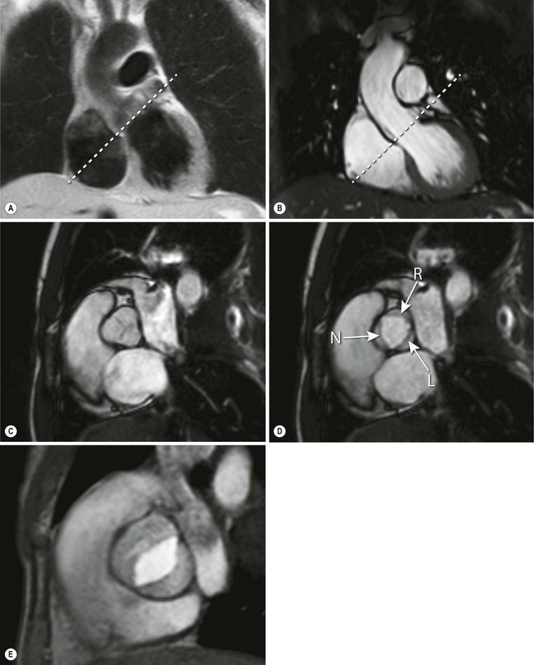
Cine SSFP long-axis and SA images, as well as transverse images, are all well suited for depicting morphology and function of the valvular apparatus. The valve leaflets can be depicted if spatial resolution is adequate. Dedicated acquisitions of specific valvular planes are used to image the valve area, which is especially useful when studying aortic valve stenosis or incompetence. Both SSFP and fast gradient-echo sequences are used for valvular imaging. Papillary muscles are well visualised on both cine bright- and black-blood sequences. Chordae tendineae, on the other hand, are difficult to visualise on CMR due to the limited spatial resolution (Fig. 19-6).
Computed Tomography Imaging Techniques
With the introduction of 64- or more slice CT imaging devices, CT has been accepted as a diagnostic imaging tool for the evaluation of patients with suspected coronary artery disease and for several other cardiac indications. This includes evaluation of cardiac structures and function in adult congenital heart disease, evaluation of ventricular morphology, left and right systolic function, the pericardium and evaluation of intra- and extracardiac structures such as valves, masses and pulmonary veins.10
Cardiac CT requires intravenous injection of iodinated contrast agent, with the exception of CT calcium scoring that requires plain cardiac CT. Various cardiac CT imaging techniques are applied in clinical practice, depending on the CT device used, on the clinical question that must be answered and on patient-related parameters. Imaging can be performed with helical acquisition, with step-and-shoot ‘sequential’ acquisition or with wide-volume acquisition. With helical and with step-and-shoot acquisition, multiple heart beats are needed for cardiac imaging that requires a breath-hold of approximately 10 s. Images are reconstructed with a slice thickness down to 0.5 mm, with a temporal resolution down to 83 ms. Also, fast dual source helical techniques and wide-volume detectors that cover the whole heart allow for imaging of the heart within a single heart beat at radiation doses below 5 mSv.11,12
ECG recording is central in all cardiac CT techniques as to avoid motion artefacts. Patients are generally prepared with beta-blockers to slow down the heart rate below 65 beats per minute for optimal image quality. If only anatomical/morphological information is required, such as in coronary artery imaging, the acquisition can be prospectively triggered. This allows imaging during a predefined cardiac rest phase with least motion, which is at mid-diastole at approximately 75% of the cardiac -R cycle. In patients with high heart rates that are susceptible to motion artefacts, image acquisition may be performed with a wider acquisition interval during the cardiac cycle, allowing for selection and reconstruction of multiple cardiac phases for optimal motion-free imaging of each coronary artery.13
Related posts:
Stay updated, free articles. Join our Telegram channel

Full access? Get Clinical Tree


