Fig. 21.1
Illustration of the radiofrequency ablation procedure. After traditionally percutaneous venous femoral access, a transseptal catheter puncture is performed to gain access to the left atrium (Panel A). Next, the catheter with an ablation electrode at its tip is placed at the level of an atriopulmonary venous junction – in this case the upper left pulmonary vein (Panel B). Finally, ablation is performed: a circular Lasso catheter is used for electrical mapping guidance at the atriopulmonary venous junction (the wall of which has myocardial tissue extending from the left atrium), while a linear catheter with ablation electrode performs a radiofrequency ablation at a specific point (Panel C). Panel D shows a three-dimensional fast anatomic mapping image of the left atrium acquired by dragging a mapping catheter over sites of interest along the atrial endocardial wall. The final ablation points (red in Panel B) surround the pulmonary vein entrances into the left atrium in a circular fashion, achieving as such electrical isolation (Panels A–C) (With permission from Ghaye et al., Radiographics, 2003)
21.2.1 Role of CT
Both CT and magnetic resonance imaging (MRI) can be used to acquire the required preoperative information. The choice between these two imaging modalities often depends on the local expertise and available equipment. While MRI has the advantage of not involving ionizing radiation and using a generally safe gadolinium-based contrast agent, it is nevertheless a more complex technique, making its implementation less practical. Therefore, CT has been increasingly used for this purpose, offering exquisite anatomic visualization in a short examination time with little physician input.
An overview of the clinical purpose of CT in the preprocedural evaluation of patients with atrial fibrillation is given in Table 21.1. CT is also an excellent tool for detection of short- and long-term procedural complications (Table 21.2).
Table 21.1
Purposes of CT in patients prior to electrophysiology procedures in atrial fibrillation
Item/structure | What to consider |
|---|---|
Left atrial wall & cavity | Atrial thrombus: specifically in the left atrial appendage |
Atrial diverticula or other potential obstacles | |
Pulmonary veins | Number and location |
Size of ostia: specifically the presence of conjoined veins | |
Accessory veins or abnormal pulmonary venous return | |
Interatrial septum | Interatrial shunts: patent foramen ovale, atrial septal defect |
Lipomatous septal hypertrophy | |
Septal aneurysm or septal closure device | |
Periatrial structures | Anatomic relationship with the esophagus |
Other ancillary findings | Any finding that could alter the execution of the procedure or influence treatment |
Table 21.2
Complications related to radiofrequency ablation of the pulmonary vein ostia
Affected anatomy | Complications |
|---|---|
Pulmonary veins | Pulmonary vein stenosis |
Pulmonary vein occlusion | |
Pulmonary vein dissection | |
Lung & pleura | Pulmonary hypertension |
Pulmonary venous infarction | |
Pulmonary fibrosis | |
Pulmonary embolism | |
Pneumothorax | |
Hemothorax | |
Pleural effusion | |
Heart & pericardium | Pericarditis |
Hemopericardium & cardiac tamponade | |
Cardiac perforation | |
Coronary artery spasm & myocardial infarction | |
Valve damage | |
Atrioesophageal fistula | |
Other | Systemic thromboembolism |
Phrenic nerve palsy | |
Hematoma at puncture site | |
Arteriovenous fistula |
21.2.2 Scan Protocol
One of the most important goals of a preprocedural CT investigation is the acquisition of a high-quality three-dimensional dataset to be used for image integration during the transcatheter ablation procedure. At first glance, this acquisition is similar to a standard cardiac CT protocol for evaluation of the coronary arteries. However, many patients referred prior to EP will have atrial fibrillation at the time of the CT examination, very often causing significant image artifacts on an ECG-triggered CT acquisition. Consequently, while an ECG-triggered acquisition is traditionally preferred for coronary angiography (Chap. 8), a case can be made for non-gated examinations in patients with atrial fibrillation. A non-gated scan can both provide sufficient image quality and reduce radiation exposure (Chap. 7) while shortening the examination time. Nevertheless, in dual-source CT systems using high-pitch protocols and CT systems with large volumetric coverage, ECG-triggered acquisitions can also result in good image quality in patients with atrial fibrillation.
Finally, a major concern raised by (especially prolonged) atrial fibrillation episodes is the formation of thrombi in the left atrium secondary to the altered wall motion, representing one of the most important causes of stroke-related morbidity and mortality. Thrombi predominantly form in the left atrial appendage (LAA) and are often the source of peripheral emboli and consequently the target of appendage occluder devices (Fig. 21.2). Since an atrial thrombus is a contraindication to an EP intervention, a concise evaluation of the LAA is an essential part of every preprocedural CT examination. Caution is however needed as incomplete filling of the LAA is not an infrequent finding in CT scans of the heart performed in the arterial phase, especially when the LAA is enlarged (Fig. 21.3). As such, this phenomenon produces a false-positive image with a low-attenuation filling defect mimicking an atrial appendage thrombus due to circulatory stasis. An LAA filling defect therefore needs to be confirmed with an additional delayed-phase scan (albeit at the cost of extra radiation exposure) or with transesophageal echocardiography.
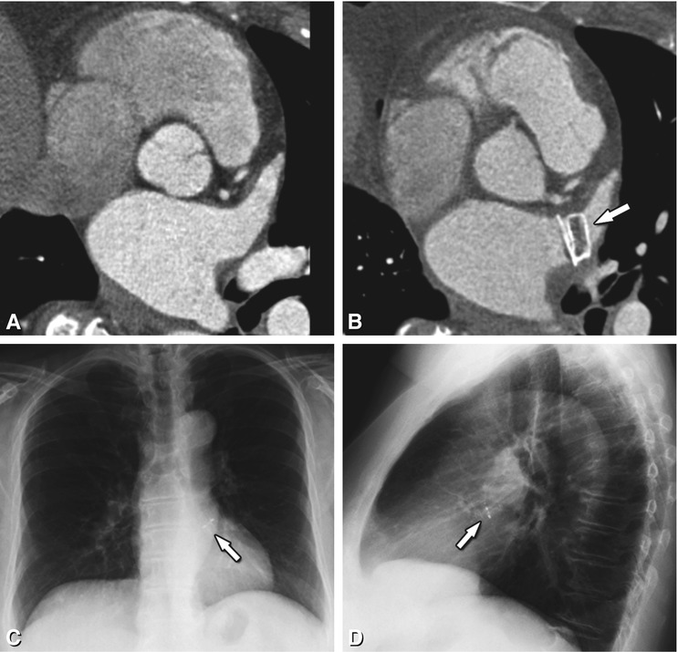
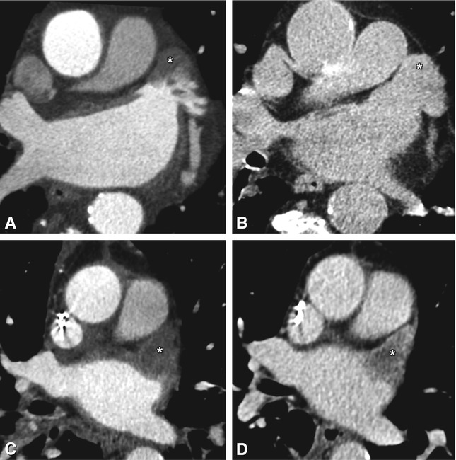

Fig. 21.2
Axial contrast-enhanced CT image in a 67-year-old female before (Panel a) and after (Panel b) placement of a left atrial appendage occluder device (Amplatzer Cardiac Plug 20 mm, arrow in Panel b). The device is also seen on frontal (arrow in Panel c) and lateral (arrow in Panel d) conventional chest radiographs. Since the left atrial appendage is a major source of thrombus formation due to circulatory stasis, the use of an occluder device here can dramatically reduce the risk of thromboembolic stroke. In this particular patient, anticoagulation therapy could be stopped after device placement. However, this approach is currently controversial, as some investigators argue that there are also other potential sources of emboli, including the atrial septum, left-sided valves, and the aorta. Furthermore, since stroke risk in atrial fibrillation is a systemic problem, occlusion of the left atrial appendage is by some considered only part of the treatment; consequently they continue to promote antithrombotic medication as the standard treatment for preventing stroke in patients with atrial fibrillation

Fig. 21.3
Axial contrast-enhanced CT of two patients with paroxysmal atrial fibrillation prior to radiofrequency ablation, showing a left atrial appendage pseudothrombus (Panels A and B) and real thrombus (Panels C and D). Occurring especially in large atria and in patients with atrial fibrillation, slow blood flow can range from moderate to very pronounced (asterisk in Panel A). In this patient, absence of a thrombus was confirmed by delayed-phase imaging (asterisk in Panel B). Therefore, diagnosis of a left atrial appendage thrombus should only be retained after a filling defect has been confirmed on delayed-phase imaging or with transesophageal ultrasound. In the second patient, the left atrial appendage is completely filled with a hypodense mass on arterial-phase imaging (asterisk in Panel C), which persists on delayed-phase imaging (asterisk in Panel D) with only discrete further opacification surrounding the thrombus. Confirmation of the diagnosis is clinically important, as the presence of a left atrial appendage thrombus is a contraindication to an EP procedure
21.2.3 Postprocessing
After the CT examination, the data are digitally transferred to the EP room for further processing. In our institution, we provide an additional dataset containing only the left atrium and the atriopulmonary junctions of the different veins with a short adjacent vein segment. While this is not strictly necessary, the familiarity of the radiologist with cross-sectional cardiac anatomy, along with solid knowledge of the often-used postprocessing tools on CT workstations, can lead to a more reliable end-result than the use of less specialized software in the EP lab by non-radiologists. We also routinely generate three-dimensional volume-rendered images of the left atrium and its pulmonary veins, providing an anatomic overview unmatched by ultrasound (Fig. 21.4). Measurement of the size of the pulmonary vein ostia is not routinely done.
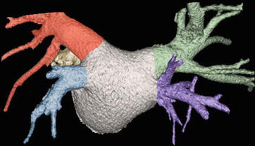

Fig. 21.4
Volume-rendered CT image of the left atrium, atriopulmonary venous junctions, and a short adjacent segment of the pulmonary veins. CT is an excellent tool for anatomic evaluation as echocardiography does not consistently visualize all pulmonary arteries. The normal three-dimensional anatomy of the pulmonary veins is illustrated, which includes the right superior (green), right inferior (purple), left superior (red), and left inferior (blue) pulmonary veins. The right superior pulmonary vein drains the right upper and middle lobe, with the left superior pulmonary vein draining the left upper lobe and lingula. The right and left inferior pulmonary veins drain the lower lobes of their respective lungs. This anatomic configuration occurs in 60–70% of patients. A portion of the left atrial appendage (yellow) can be seen anterior to the left pulmonary veins
21.2.4 Preprocedural Clinically Relevant Anatomy
A correct description of the anatomy of the pulmonary veins and left atrium, specifically mentioning important anatomic variations that can alter the procedural strategy, should always be the first item reported. Typically, a total of four pulmonary veins with four independent ostia can be distinguished on both sides of the left atrium (Fig. 21.4). They are appropriately named right superior, right inferior, left superior and left inferior pulmonary vein. The most common anatomic variations are the presence of common (or conjoined) veins and accessory or supernumerary pulmonary veins (Fig. 21.5). Other more rare variants must also be reported as they can influence catheter passage (Fig. 21.6).
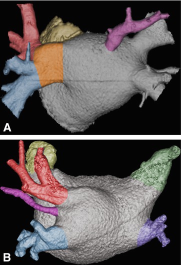
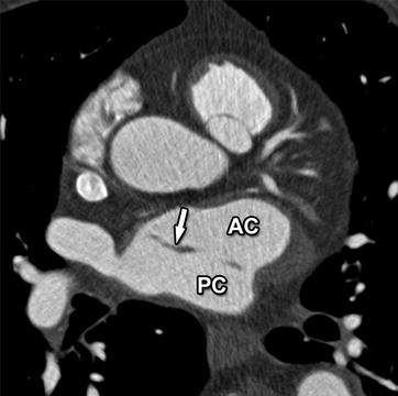

Fig. 21.5
Variant pulmonary vein anatomy in two patients with paroxysmal atrial fibrillation. Volume-rendered CT images are shown. An accessory vein (purple) is present in both cases, centered on the posterior atrial wall in Panel a and between the upper and lower left pulmonary veins in Panel b. Preprocedural detection of these accessory veins is important, since they are easily seen with CT but can be missed on less detailed fast anatomic mapping images acquired during the EP procedure. It is in such cases that integration of CT and EP-derived data can lead to the best roadmap for successful intervention. Furthermore, they have often small ostia (as especially illustrated in Panel b), making them more at risk for complications such as stenoses. Additionally, in Panel a there is a congenital confluence of the left superior (red) and inferior pulmonary vein (blue) in one large common trunk (orange in Panel a). Note the large diameter of this common vein segment, making this a preferred target for electrical isolation. This common variant occurs in 12–25% of the population, mostly on the left side

Fig. 21.6
Axial contrast-enhanced CT image in a 70-year-old man revealing an incidentally found cor triatriatum, with a fenestrated fibromuscular membrane (arrow) dividing the left atrium into an intercommunicating anterior (AC) and posterior chamber (PC). This is a rare congenital heart defect of unknown origin, possible secondary to malincorporation of the embryonic common pulmonary vein into the left atrium. Its presence can compromise stable and correct positioning of the ablation catheter during EP interventions and should therefore be reported. Practically, while it increases procedural complexity, a fenestrated membrane will generally not preclude a radiofrequency ablation intervention, as the electrophysiologist will try to use the fenestrations for passage of the catheter between the atrial chambers
The presence of large ostia, as sometimes seen in conjoined pulmonary veins, must be reported as they may be prime targets for ablation even without any other evidence of atrial fibrillation foci (Fig. 21.5). Overall, both CT and MRI have been reported to deliver more accurate and comparable ostial measurements than transesophageal echocardiography, which often underestimates these dimensions and does not consistently visualize all pulmonary veins.
As positioning of the radiofrequency ablation catheter in the left atrium is achieved through puncture of the interatrial septum from the right atrium, evaluation of this septum is critical. In about 25–35% of patients, transseptal passage might be facilitated by the presence of a patent foramen ovale (PFO), a small potential interatrial shunt secondary to a lack of fusion between the septum primum and septum secundum (Fig. 21.7). While a PFO can exist without any detectable shunt, a small left-to-right shunt is common and often of little clinical significance. It can nevertheless become clinically important when left atrial pressure rises as in arterial hypertension for instance. Conversely, any temporary rise of right atrial pressure (e.g. coughing) can provoke a right-to-left shunt with the risk of paradoxical embolism.
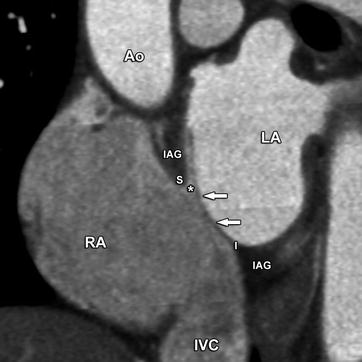

Fig. 21.7
A patent foramen ovale in a young woman. Slightly oblique coronal contrast-enhanced CT image obtained perpendicular to the interatrial septum at the level of the fossa ovalis. The superior (S) and inferior (I) rims of the fossa ovalis are formed by the septum secundum or interatrial groove (IAG). A patent foramen ovale is the result of failed fusion between the septum primum (arrows) and the septum secundum at the fossa ovalis, producing a potential communication between left and right atrium (asterisk). In this typical case, the septum primum (arrows) is fused to the inferior rim of the fossa ovalis (I) and extends superiorly as a flap. A patent foramen ovale is a common finding in the general population, with prevalence estimates in autopsy studies ranging from 25 to 35%. Small left-to-right shunts are commonly seen, where the passage of blood is always oblique between the partially overlapping ostium primum and secundum. This is a distinguishing feature compared with atrial septal defects, where the flow direction is perpendicular to the axis of the interatrial septum. Small shunts are of no clinical significance. The presence of a patent foramen ovale facilitates transseptal passage of the catheter during radiofrequency ablation procedures. Ao aorta, RA right atrium, LA left atrium, IVC inferior vena cava
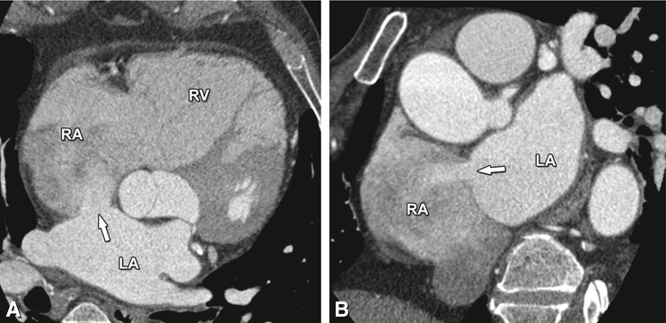
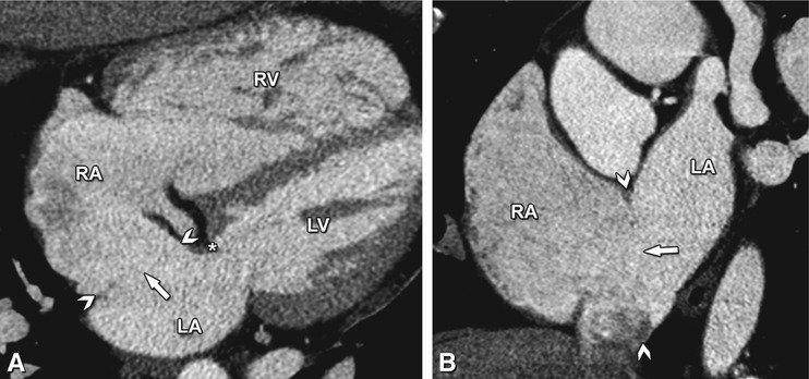
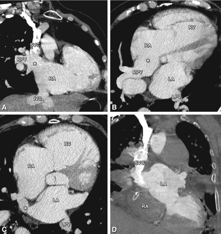
A PFO must be distinguished from a true atrial septal defect (ASD), an interatrial communication which is always patent and has greater clinical impact because the shunt tends to be larger in many cases. Three major types of ASD can be distinguished, with an ostium secundum ASD being the most frequently encountered type (Figs. 21.8, 21.9, and 21.10). One of the distinguishing features between an ASD and a PFO on CT is, besides location, the direction of the shunt flow (compare Fig. 21.7 with Fig. 21.8).
Get Clinical Tree app for offline access

Fig. 21.8
Axial (Panel a) and coronal (Panel b) contrast-enhanced CT images in a middle-aged woman, illustrating an ostium secundum atrial septal defect as a discontinuity of the interatrial septum of about 1.5 cm length, with a left-to-right shunt illustrated by the passage of contrast-enhanced blood from the left to the right atrium (arrow in Panels a and b). Contrary to a patent foramen ovale, the flow is perpendicular to the axis of the interatrial septum through a septal defect without an overlapping flap. Atrial septal defects constitute 10% of all congenital heart diseases, with an ostium secundum defect being the most common type, accounting for 75% of all cases. In comparison with a patent foramen ovale, an atrial septal defect is a more rare but often clinically more relevant congenital defect. Small defects are usually asymptomatic, especially in the first three decades of life, and often do not require treatment. However, large shunts can initially cause volume and eventually pressure overload of the right heart with atrial and ventricular dilatation (as illustrated in this case), leading to pulmonary hypertension, right ventricular failure, and potentially right-to-left shunting. As a consequence, over 70% of individuals with an atrial septal defect become symptomatic in the fifth decade, or even earlier when the shunt is large. Depending on the characteristics of the atrial septal defect, treatment is endovascular or surgical. RA right atrium, RV right ventricle, LA left atrium

Fig. 21.9
Four-chamber (Panel a) and short-axis (Panel b) contrast-enhanced CT images in a middle-aged woman illustrating an ostium primum atrial septal defect (arrowheads in Panels a and b). A large communication between the left and right atrium is seen (arrow in Panels a and b), just posterior to the annulus of the mitral valve (asterisk in Panel A). Note the absence of septal flaps as in a patent foramen ovale and the enlargement of the right ventricle (RV) secondary to the shunt-induced volume overload. In contrast to an ostium secundum atrial septal defect, an ostium primum defect is often large and located in the most anterior and inferior part of the interatrial septum, immediately adjacent to the atrioventricular valves. Mostly, it is associated with a cleft in the anterior leaflet of the mitral valve. Ostium primum septal defects account for 15% of all atrial septal defects. RA right atrium, LA left atrium, LV left ventricle


Fig. 21.10
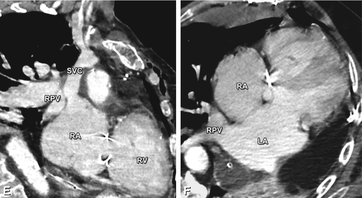
Coronal (Panel a) and axial (Panels b and c) contrast-enhanced CT images in a 72-year-old man with increasing shortness of breath illustrating a sinus venosus defect, a third type of atrial septal defect involving the junction of the superior vena cava (SVC) with the right atrium (RA). Representing 10% of atrial septal defects, its name is derived from the abnormal fusion between the embryologic sinus venosus and the atrium. Instead of draining into the left atrium (LA), the right pulmonary veins (RPV) conjoin with the distal SVC into the RA (asterisk


Stay updated, free articles. Join our Telegram channel

Full access? Get Clinical Tree


