Knee MRI
INTRODUCTION
Magnetic resonance imaging (MRI) interpretation of the knee is often a daunting challenge to the student or physician in training. After all, an entire year of fellowship training is dedicated to musculoskeletal imaging. To overcome this challenge, it is imperative for both the medical student and resident in training to achieve a fundamental understanding of the structural and functional anatomy of the knee. Thus, the initial goal of this chapter is to review the complex anatomic relevant components of the knee. After establishing this anatomic knowledge base, a second goal of this chapter is to provide a systematic approach for interpretation of MRI as it applies to the clinical presentation of internal derangement of the knee. The term “Internal Derangement” is used to cover a group of disorders that affect the normal functioning ligaments, tendons, or cartilage (including the meniscus) of the knee articulation. From a technical standpoint, this is ideally performed with a high field strength 1.5 Tesla or 3 T MRI scanner. Three conventional MRI planes that are utilized to evaluate the knee include sagittal (oblique), coronal, and transaxial planes. While a detailed explanation of MRI protocols and MR physics is beyond the scope of this text, fast spin echo (FSE) MRI is most commonly utilized for MRI of the knee. Specifically, in the coronal and sagittal planes, T1, T2, and intermediate-weighted proton density FSE sequences are often utilized. Fat saturation is employed on some of the fluid-weighted sequences to better detect the presence of edema in the soft tissues or bone marrow. A spin echo or gradient echo sequence is often acquired in the transaxial plane. MRI of the knee may be performed without contrast. Alternatively, utilization of gadolinium contrast agent may be utilized and with regard to internal derangement; this is particularly useful in evaluating the postoperative knee. Administration of gadolinium for an MR arthrogram may be employed. This may be performed with either a direct or indirect technique. With the direct MR arthrogram, a 1:200 dilution of gadolinium in approximately 30 mL of sterile saline is percutaneously injected into the knee joint using a 22-gauge needle. The indirect MR arthrogram is performed after an intravenous injection of gadolinium contrast followed by exercise allowing leakage of contrast agent from the synovium into the joint space and then subsequent MR image acquisition.1
ANATOMY
 Patellofemoral Articulation
The patella is the largest sesamoid bone in the body, and the osseous contour of its articular surface is composed of a lateral facet, a pointed apex, a medial facet, and a smaller odd facet located at its far medial periphery. The patella articulates with the anterior femur that is characterized by a midline trochlear groove or sulcus, a medial facet, and a lateral facet. The articular surfaces of these patellar and femoral facets are covered with hyaline articular cartilage. A group of tendon fibers composed of the vastus medialis, vastus lateralis, and vastus intermedius, and rectus femoris converge to form the quadriceps tendon that attaches to the superior pole of the patella. The patellar tendon extends from the inferior pole of the patella to the tibial tuberosity. These are the main structural components of the extensor mechanism of the knee. There are two bursa located superficially to the extensor mechanism and these include the prepatellar bursa and the superficial infrapatellar bursa. The deep infrapatellar bursa is located dorsally with respect to the patellar tendon and immediately superior to its tibial tuberosity attachment. The knee joint capsule is a fibrous retinaculum arising from the osseous peripheral margins of the patella and propagates in a dorsal direction converging with the anteromedial and anterolateral margins of the femoral and tibial condyles. It is at these respective locations where the patellofemoral retinaculum converges medially with the MCL complex and laterally with iliotibial band. Deep to the joint capsule, three fat pads at the patellofemoral articulation are clinically relevant. These intracapsular but extrasynovial fat pads include the infrapatellar fat body of Hoffa, the suprapatellar fat pad, and the prefemoral fat pad. Hoffa fat pad is located dorsally to the patellar tendon and patellofemoral retinaculum. The inferior margin of Hoffa’s fat pad is attached to the periosteum of the tibia and abuts the deep infrapatellar bursa. In 65% of knees, the deep midline margin of Hoffa’s fat pad gives rise to a fan-shaped infrapatellar plicae or ligamentum mucosum that narrows as it propagates into the intercondylar notch paralleling the course to the anterior cruciate ligament (ACL).2 The deep peripheral margins of Hoffa’s fat pad are attached to the anterior horns of the medial and lateral meniscus respectively. The suprapatellar fat pad (or quadriceps fat pad) is located between the quadriceps tendon and the suprapatellar recess of the knee joint. Dorsal to this, the prefemoral fat pad is located between the suprapatellar recess and the anterior surface of the femur. These fat pads line the synovial membrane of the knee joint. Extending vertically above the level of the patella is the suprapatellar synovial pouch. The articularis genus muscle, the final component of extensor mechanism, arises from the distal portion of the femur and inserts into the suprapatellar pouch. The central portion of synovial anatomy is located essentially deep to Hoffa fat pad and superficially to the cruciate ligaments. In approximately 55% of knees, a suprapatellar plicae may be present and in 25% of knees, a medial patellar plicae may be identified (Figure 13-1). These plicae are anatomic normal variants representing remnants of synovial tissue from early development.3
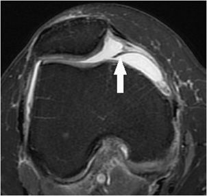
Figure 13-1. Medial patellar plicae. Axial proton density fat-saturated image demonstrating a normal variant from early development band-like remnant of synovium (arrow) that protrudes into the medial aspect of the patellofemoral articulation. While this case is not significantly thickened, plicae that are greater than 2 mm in thickness may be clinically symptomatic.
 Intercondylar Notch
Within the intercondylar femoral notch are the two cruciate ligaments named specifically as anterior and posterior based on the position of their attachments to the tibia (Figure 13-2). These ligaments are intracapsular but extrasynovial and are therefore lined by a synovial sheath. The ACL is composed of two components designated as the anterior medial bundle and posterior lateral bundle. The tibial footprint of the ACL is located in front of the intercondylar eminence of the tibia. The ACL propagates in a proximal–posterior–lateral orientation and attaches to the dorsal inner margin of the lateral femoral condyle. The ACL serves as the primary restraint to anterior displacement of the tibia and secondary restraint to internal tibial rotation. The posterior cruciate ligament (PCL) is composed of an anterolateral and posteromedial bundle. The PCL is attached to the posterior intercondylar fossa of the tibia and propagates in a proximal–anterior–medial orientation where it attaches to the anterior inner margin of the medial femoral condyle. The PCLs function as the primary restraint to posterior displacement of the tibia and as a secondary restraint to external tibial rotation. Variably passing nearly perpendicular to the PCL are normal variant accessory ligaments of the knee that more commonly connect the lateral meniscus to the osseous intercondylar portion of the medial femoral condyle. When this meniscofemoral ligament passes anteriorly to the PCL, it is referred to as the ligament of Humphrey. When it passes dorsally with respect to the PCL, is referred to as the ligament of Wrisberg. A clinically relevant fat pad located in the posterior aspect of the intercondylar notch is the retrocruciate fat pad that is located between the PCL and the posterior portion of the joint capsule.
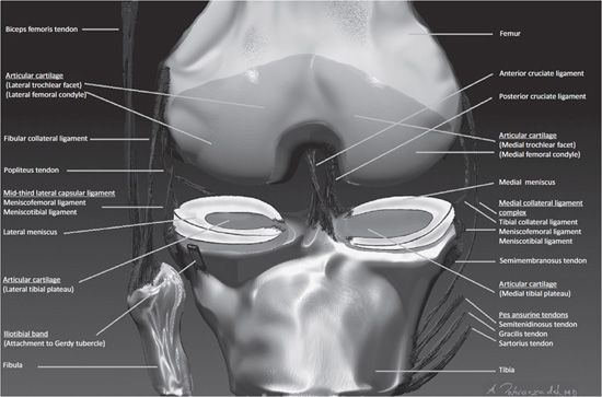
Figure 13-2. Coronal anatomy of the knee. Intercondylar notch. Anterior and posterior cruciate ligaments. Medial knee. From superficial to deep includes the pes anserinus tendons, semimembranosus tendon, tibial collateral ligament, meniscofemoral and meniscotibial ligaments, and the medial meniscus. Lateral knee. From superficial to deep includes the iliotibial band, fibular collateral ligament, and posteriorly the biceps femoris tendon. Deep to these structures is the popliteus tendon. The deeper layer is composed of the mid-third lateral ligament, meniscofemoral and meniscotibial ligaments, and the lateral meniscus.
 Medial Knee
The supporting components in the medial aspect of the knee are described in layers from superficial to deep (Figure 13-2). Superficial to the knee joint capsule is the pes anserinus. This refers to the conjoined tendons of the sartorius, semitendinosus, and gracilis muscles that originate at the level the pelvis and propagate toward the medial margin of the knee in a pattern that is visually analogous to a goose’s webbed foot when viewed in the sagittal plane. They insert distally at the anteromedial proximal cortical diaphysis of the tibia. Immediately deep to these tendons is the pes anserine bursa. Deep to the pes anserine bursa at the posteromedial aspect of the knee is the tibial attachment site of the semimembranosus tendon that is responsible for flexion and internal rotation of the knee. Intimate with this tendinous attachment is the bursa semimembranosus. Immediately anterior to the footprint of the semiembranosus tendon and deep to the pes anserine tendons and bursa is the medial collateral ligament (MCL) complex of the knee. This ligamentous complex is composed of a superficial layer and a deep layer. The superficial layer refers to the tibial collateral ligament that is vertically oriented and extends from the supracondylar portion of the femur to the proximal tibial diaphysis. The deep layer of the MCL complex is composed of two ligaments that converge with the superior and inferior meniscosynovial junction of the medial meniscus. The superior ligament of the deep layer is termed the meniscofemoral ligament. The inferior ligament of the deep layer is referred to as the coronary ligament or meniscotibial ligament. Between the superficial and the deep layer of the MCL complex is the medial collateral ligament bursa. These ligamentous capsular reflections at the peripheral aspect of the medial knee confine the medial compartment. The femoral and tibial articular surfaces of the medial compartment are diffusely lined with hyaline articular cartilage. Attached to the peripheral capsular reflections of the medial compartment, particularly to the deep fibers of the tibial collateral ligament, is the medial meniscus that is composed of fibrocartilage. The medial meniscus is situated between the articular surfaces of the femoral condyle and the tibial plateau. From a bird’s-eye view, the medial meniscus is located at the circumferential periphery of the medial compartment, has a semicircular shape, and its width is greater posteriorly than anteriorly. The red zone is the vascularized portion of the meniscus located closest to the capsular attachment and specifically involves the outer 5–30% peripheral circumferential margin of the meniscus. The white zone corresponds to the avascular central majority of the meniscus that extends to its free edge.4 Nerve fibers enter the vascularized red zone and propagate toward the white zone. Anatomic landmarks of the medial meniscus are referred to as the anterior horn, body, and posterior horn. The anterior and posterior horns are attached to the tibial surface located at the inner aspect of the knee and are respectively designated as the anterior and posterior tibial root attachments. The anterior tibial root attachment is located in the flat intercondylar region of the anterior inner tibia. The posterior tibial root attachment is located immediately anterior to the tibial attachment of the PCL. The function of the meniscus is multifaceted and includes shock absorption, transmission of load, joint stabilization, limitation of extreme range of motion, and lubrication of the articulation.3
 Lateral Knee
Similar to the medial aspect of the knee, the lateral knee supporting structures are described in layers from superficial to deep (Figure 13-2). The iliotibial band is a vertically oriented ligamentous fascia that attaches to Gerdy tubercle that is located at the anterolateral aspect of the proximal tibia. The fibular collateral ligament (e.g., lateral collateral ligament) is a static stabilizer of the posterior lateral cornering the knee, and this extracapsular ligament has a vertical-oblique orientation attaching to the lateral epicondyle of the femur and extending distally and posteriorly to the lateral aspect of the fibular head. A large bursa covers a portion of the ligament. The biceps femoris tendon attaches to the fibula. The mid-third lateral ligament capsule reflects the meniscofemoral and meniscotibial ligaments that were similarly described at the medial aspect of the knee. The popliteus tendon originates from the posterior inner aspect of the knee and wraps around the posterior lateral aspect of the knee to insert on the lateral femoral epicondyle. As it courses through the posterior lateral aspect of the knee, it creates a synovium called the popliteal hiatus that lies adjacent to the posterior horn of lateral meniscus. The lateral meniscus is circular in appearance when compared with the medial meniscus. Consequently, at the inner aspect of the lateral compartment, the anterior and posterior horn tibial root attachments are in close proximity to each other. The lateral meniscus has a loose posterior peripheral attachment where it is separated from the capsule by the popliteus tendon and its sheath. Superior and inferior capsular popliteal meniscal fascicles attach to the peripheral margin of the lateral meniscus posterior horn.5 Thus, the lateral meniscus is more mobile than the medial meniscus. For example, during flexion, the lateral meniscus may move as much as 1 cm, but the medial meniscus will only move a few millimeters.6 Hyaline articular cartilage covers the weight-bearing articular surface of the lateral femoral condyle and opposing lateral tibial plateau. At the posterior lateral corner of the knee, located distally to the posterior horn fascicles, is the arcuate ligament. This arch-type ligament is composed of a medial arm and a lateral arm. The medial arm extends from the posterior joint capsule at the level of the distal femur and propagates medially onto the popliteus muscle where it converges with the oblique popliteal ligament. The lateral arm of the arcuate ligament extends from the posterior capsule and courses laterally over the popliteus muscle and inserts on the posterior aspect of the fibula. Deep to the lateral arm of the arcuate ligament is the popliteofibular ligament that arises from the fibula (posterior to the biceps insertion) and extends toward the musculotendinous junction of the popliteus.7
 Pathology—Internal Derangement of Cartilage
Hyaline articular cartilage is composed primarily of collagen and proteoglycans and provides an extremely smooth surface to tolerate high pressures and velocities across the full kinematic range of motion. Extending from its superficial surface to its deepest layer, the articular cartilage is composed of four zones, each of which is composed of a variation in structural matrix and proteoglycan content. The zones include the superficial, transitional, radiated stratum, and calcified stratum zones. The largest zone comprising 70–80% of the cartilaginous thickness is the radiated stratum. Cartilaginous injury may be a consequence of either acute or chronic insult and consequently will result in a structural change in the cartilaginous matrix resulting in softening or intrasubstance blistering in the early stage. Progressive cartilaginous lesions include fissuring, fibrillation, erosion, end-stage exposure of the subchondral bone, and finally subchondral cyst formation indicating osteoarthritis. Arthroscopic assessment is performed by visualization and probing of the articular cartilage. A common classification system for chondromalacia is the Outerbridge grading system defined as follows: (grade 0) normal cartilage, (grade 1) softening and swelling of the cartilage, (grade 2) ≤1 cm diameter focus of fissuring and fragmentation, (grade 3) ≥1 cm diameter focus of fissuring and fragmentation, and (grade 4) a full-thickness erosion with exposure of subchondral bone.8
 Radiologic Findings—Internal Derangement of Cartilage
MRI has been shown to be both sensitive and specific for detection of chondral abnormalities, particularly high-grade lesions, and for fundamental imaging findings including attenuation of the cartilage thickness and alteration in the intrasubstance signal intensity. MR classification system for grading chondromalacia is based on the Outerbridge arthroscopic grading system and is defined as follows: (grade 0) normal cartilage; (grade 1) surface contour +/– altered intrasubstance signal; (grade 2) superficial fraying, erosion, or ulceration of <50% of the cartilaginous thickness; (grade 3) partial-thickness defect of ≥50% and <100% of the cartilage thickness; and (grade 4) full-thickness cartilage loss.9 A variety of MRI protocols may be utilized to evaluate articular cartilage and these include conventional spin echo, FSE, gradient-recalled echo, isotropic three-dimensional spin echo and gradient-recalled echo techniques, T2 mapping, and diffusion-weighted imaging. One example of these more advanced techniques is the T2 mapping that takes advantage of the T2 sequence which is highly sensitive to increased interactions between water and macromolecules in the collagen matrix [Figure 13-3A–C (for part C see color insert)]. In chondromalacia, loss of the normal T2 homeostasis can be mapped with a color-coded parametric image that reflects variations in the MR relaxation time in the cartilage.10,11 After failure of conservative treatment, surgical therapy for chondromalacia may be performed with either shaving or excisional procedures at the chondral surface or microfracture and drilling of the subchondral bone to stimulate the formation of fibrocartilage. Advanced techniques may include reconstructive autologous chondrocyte or osteochondral implantation, and these reconstructive procedures may be monitored postoperatively by MRI. The advantage of MR arthrography is that the contrast fills the defect in the articular cartilage providing improved visualization of superficial changes. The disadvantage of MR arthrography is that it is more time consuming and invasive. An acute osteochondral defect or the separate entity of a chronic sequelae of prior injury known as osteochondritis dissecans involves both the cartilage and the portion of the underlying subchondral bone (Figure 13-4A,B). These lesions may be stable or unstable depending on if the osteochondral fragment is ballotable at the time of arthroscopy. Grossly unstable lesions are associated with a disrupted chondral surface and partial or complete separation of the fragment. MRI criteria to gauge stability are based on the intrusion of fluid or contrast into the junctional zone located between the osteochondral fragment and the parent bone.12
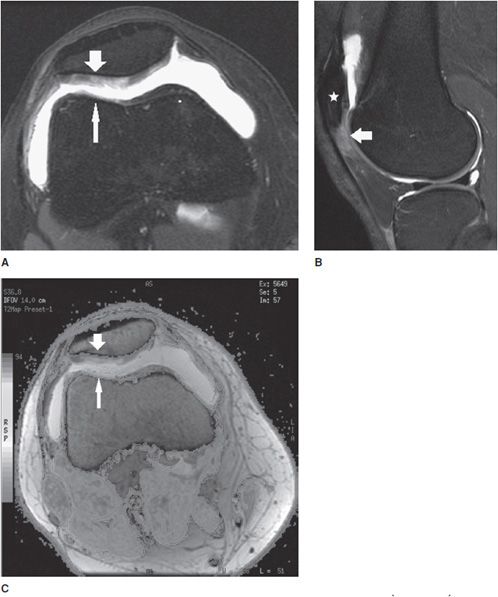
Figure 13-3. Chondromalacia patella with Patellar Tendon-Lateral Femoral Condyle Friction Syndrome (Fat Pad Impingement Sydrome). (A) Axial proton density fat-saturated image through the patellofemoral joint demonstrates diffuse grade 3 chondromalacia in the lateral patellar facet (wide arrow) characterized by fibrillation involving greater than 50% but less than 100% of the axial cartilage thickness. Chondromalacia is also present in the opposing lateral trochlear facet (thin arrow). (B) Sagittal proton density fat-saturated image through the lateral patellofemoral articulation in the same patient demonstrates associated soft tissue edema dorsal to the patella alta (star) and located specifically in the superolateral aspect of Hoffa fat pad (arrow) that is seen in the clinical setting of Patellar Tendon-Lateral Femoral Codyle Friction Syndrome. (C) Axial T2 mapping color-coded cartogram sequence in the same patient demonstrates loss of the normal T2 homeostasis in the cartilage demonstrated by a change in the cartilage color scale from a “normal red color” to an abnormal yellow color in the lateral patellar facet (wide arrow) and also to an abnormal green color in the opposing lateral trochlear facet (thin arrow). See color insert.
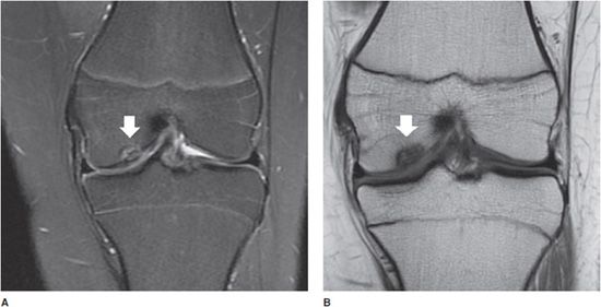
Figure 13-4. Osteochondritis dissecans. (A) Coronal proton density fat-saturated image in a 14-year-old with knee pain. An osteochondral defect is present in the inner central weight-bearing aspect of the medial femoral condyle (white arrow). (B) Coronal T1 image in the same patient shows the same the lesion.
 Pathology—Internal Derangement of Ligaments and Tendons
Proper nomenclature should be utilized in order to prevent confusion when communicating imaging findings. Ligamentous injuries are referred to as “sprains”. Injuries to the muscle are designated as “strains,” and when there is internal derangement of a tendon, the term “tendinosis” is applied. The term “tendinitis” is better applicable when there is an inflammatory component. In the setting of infection, inflammation, or overuse, fluid may collect circumferentially around the surface tendon proper and deep to its surrounding anatomic tendon sheath, and in this latter scenario, the term “tenosynovitis” is applied. Injuries to tendons and ligaments vary in severity, and traditionally, a three-grade classification system to ligamentous sprains and tendinosis is applied, respectively. A grade 1 injury is mild and presents with soft tissue edema surrounding the ligament or tendon, but the overall structural integrity is grossly preserved. A grade 2 injury is a moderate ligament sprain or tendinosis with a partial-thickness component that is subcategorized as either delaminated or nondelaminated. A partial-thickness nondelaminated tear describes a “transverse” disruption of some but not all of the fibers. A partial delaminated tear is defined as an intrasubstance disruption that propagates “longitudinally” along a variable length of the tendon or ligament. A grade 3 injury is a complete full-thickness tear of the ligament or tendon with or without retraction.
 Radiologic Findings—Internal Derangement of Ligaments and Tendons
Given the complex anatomy of the knee articulation, it is imperative that an organized and systematic approach be applied when interpreting MR images. One may begin by evaluating the synovial space for joint effusions, evidence of synovitis, or intra-articular bodies (Figure 13-5). A thorough evaluation of the osseous cortex and bone marrow should be performed to identify the presence of edema, fracture, or other marrow abnormalities. Subsequent evaluation of the tendinous, ligamentous, and cartilaginous structures described in the anatomic portion of this chapter should be performed systematically at the patellofemoral articulation and also the medial, lateral, and posterior, and intercondylar aspects of the knee. The integrity of the ligaments and tendons should be evaluated using all three planes and with multiple sequences. The integrity of a ligament or tendon should be black or dark on all sequences in the normal setting, and in particular, the T1 sequence is useful for localizing these anatomic structures (Figure 13-6A,B). Loss of a normal dark signal intensity to an “intermediate or gray colored” signal on the T1 sequence implies either degeneration or injury. This finding should be correlated with a fluid-sensitive sequence such as a T2 or proton density, particularly with the application of fat saturation, to determine if the edema is located superficially to or within the substance of the tendon or ligament. If the abnormal signal within a portion of the tendon or ligament is isointense to fluid, then it may be categorized as a grade 2 tear (Figure 13-7 A,B). If the fluid signal traverses across the full-axial thickness of the tendon or ligament in question, and there is discontinuity of the ligament fibers, then it is designated as a grade 3 full thickness or complete tear (Figure 13-8A–D). If however there is T1-weighted “intermediate or gray signal” within the ligament or tendon substance, but lack of corresponding edema on the fluid sequence, then this indicates an old injury or chronic degeneration. Complete ligament tears in the chronic setting may become completely resorbed and this is often the presentation with a chronic complete ACL tear (Figure 13-9). The mechanism of injury to tendons and ligaments may occur from a valgus force directed to the lateral knee that creates an “open book” diastasis of the medial compartment and consequential injury to the medial knee ligaments and tendons. When a varus force is directed to the medial knee, an “open book” diastasis of the lateral compartment results in injury to the lateral supporting components. A rotational mechanism may also occur when the foot is fixed to the ground resulting in a twisting injury around the axis of the knee. This classically results in injury to the ACL. An external force directed to the anterior knee such as a dashboard injury may compromise the integrity of the PCL (Figure 13-8). A common presentation is a combination of these mechanisms of injury resulting in either anterolateral or anteromedial rotary instability. Ligament reconstruction may be performed with either an autologous or cadaveric graft harvest and this is a common therapeutic option for an ACL tear (Figure 13-10). However, ACL graft reconstructions are still prone to recurrent injury and the same grading scale may be applied to assessment of ACL graft tears and arthrofibrosis may develop near the tibial tunnel and is termed a “cyclops lesion” (Figure 13-11A–C). As similarly described in the patient without surgery who presents with a chronic ACL tear, the postoperative chronically torn ACL graft may also become resorbed (Figure 13-12).
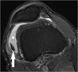
Figure 13-5. Intra-articular body. Axial proton density fat-saturated image of the knee through the patellofemoral joint. A knee joint effusion is present (star) distending the suprapatellar recess. An oval-shaped dark signal indicating an intra-articular body is present in the lateral aspect of the suprapatellar recess (arrow).
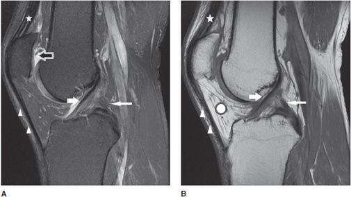
Figure 13-6. Normal cruciate ligaments. (A) Sagittal proton density fat-saturated and (B) sagittal T1 images through the level of the intercondylar notch demonstrate normal-appearing ACL (white fat arrow) and PCL (white thin arrow). Note the normal-appearing dark signal in the ligaments on both sequences. Also featured are the normal quadriceps tendon (star) and patellar tendon (triangles) that are also dark in appearance. Incidental note is made of attenuation of the patellar cartilage on image (A) indicating grade 3 chondromalacia (black arrow with white outline). The chondromalacia is not well appreciated on image (B) as the T1 sequence is not sensitive for evaluating cartilage abnormality. Hoffa fat pad is displayed (white round circle with black outline).
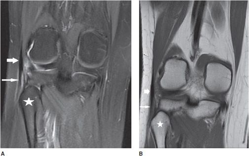
Figure 13-7. Grade 2 partial-thickness intrasubstance tear of the biceps femoris tendon. (A) Coronal proton density fat-saturated image through the level of the fibular head (star) corresponding to the insertion of the biceps femoris tendon (short fat arrow) that demonstrates intrasubstance fluid signal indicating a partial-thickness tear (long thin arrow). (B) Coronal T1-weighted image at the same level demonstrates the tear as a gray-colored intermediate signal in the tendon substance (long thin arrow).
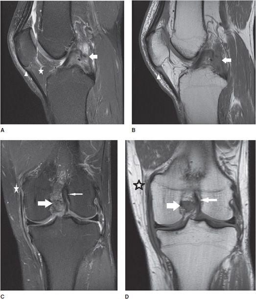
Figure 13-8. Grade 3 tear of the PCL and grade 2 tear of the tibial collateral ligament. (A) Sagittal proton density fat-saturated image in a patient with an acute injury resulting in a grade 3, and full-thickness midsubstance tear of the PCL (white arrow). Note the fluid signal traverses the full thickness of the discontinuous ligament. Associated soft tissue edema is present in Hoffa fat pad (star). Edema is present in the proximal patellar tendon but is not isointense to fluid and therefore indicates mild grade 1 tendinosis without a tear (triangle). (B) Sagittal T1 image at the same level demonstrates intermediate signal traversing through the full thickness of the PCL and note the serpiginous course of the torn fibers (white arrow). The grade 1 proximal patellar tendinosis is characterized by intermediate T1 signal involving the dorsal sided fibers at its inferior patellar attachment (triangle). (C) Coronal proton density fat-saturated and (D) coronal T1 images in the same patient show the full-thickness tear of the PCL (fat white arrow) and a normal intact ACL at its lateral femoral intercondylar attachment (thin white arrow). Also demonstrated is soft tissue edema located superficially to the tibial collateral ligament and at its femoral attachment, intrasubstance fluid and T1 intermediate signal with partial discontinuity represents a focal grade 2, partial-thickness tear (star).
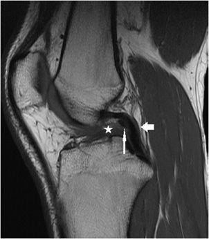
Figure 13-9. Chronic grade 3, complete ACL tear. Sagittal T1 sequence through the intercondylar notch level demonstrates absence of the ACL indicating a chronic complete tear with resorption (star). The PCL (arrow) is intact but is buckled and this is an associated imaging finding of an ACL tear. Immediately anterior to the PCL is a normal variant meniscofemoral ligament of Humphrey that is imaged in cross-section (long thin arrow).
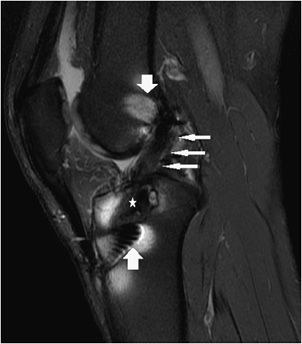
Figure 13-10. ACL reconstruction. Sagittal proton density fat-saturated image in a patient with an intact ACL graft reconstruction. Susceptibility artifact is attributed to the femoral and tibial interference screws (fat arrows). The graft is intact and characterized by its dark signal intensity along its course in the tibial tunnel (star) and along its intra-articular course (thin long arrows).
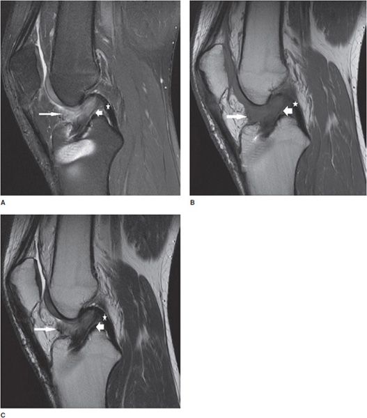
Figure 13-11. Torn ACL reconstruction with a cyclops lesion. (A) Sagittal proton density fat-saturated,(B) sagittal T1, and (C) sagittal T2 images in an acute injury resulting in a tear of the ACL graft at its intra-articular course (short fat arrow) characterized by intrasubstance edema, corresponding intermediate T1 intrasubstance signal, and discontinuity of the ligament. The majority of the graft thickness is torn, and while there are a few thin attenuated intact fibers at its dorsal margin suggesting a high-grade partial tear, the injury is essentially functionally complete. Soft tissue edema is present in the cyclops lesion located anteriorly to the torn ACL graft (long thin arrow). The PCL is intact (star).
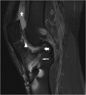
Figure 13-12. Chronic tear of an ACL reconstruction. Sagittal proton density fat-saturated image of a chronically torn ACL reconstruction demonstrates absence of the graft in the intra-articular course where it has become resorbed (short fat arrow). Fluid signal from the joint extends into the tibial tunnel where the resorbed fibers of the graft appear attenuated (long thin arrow). A synovial joint effusion distends the suprapatellar pouch (star). Incidental note is made of chondromalacia in the femoral trochlear sulcus demonstrated by alteration in the intra-substance signal of the cartilage (triangle).
 Pathology—Internal Derangement of the Meniscus
Internal derangement of the medial and lateral menisci is usually traumatic; however, degeneration of the meniscus occurs with advanced age, osteoarthritis, calcium pyrophosphate, or calcium hydroxyapatite crystal deposition diseases. In addition, meniscal lesions may be a consequence of inflammatory processes such as rheumatoid arthritis or infection in septic arthritis. Determination of a traumatic or degenerative cause is based on the clinical presentation and age of the patient. Acute traumatic tears are more commonly seen in athletes or younger patients, while degenerative tears are more common in older patients. A developmental variant is the discoid meniscus which has an altered shape that is broad and disk-like in appearance rather than semilunar. A discoid lateral meniscus (Figure 13-13) is the more common presentation, with a reported frequency of 4.5% and has a higher frequency of meniscal tears.13 Traumatic and degenerative tears of the medial or lateral meniscus may involve any portion of the meniscus from its free edge to its peripheral meniscocapsular junction. There may be involvement of the anterior and posterior horn of meniscal tibial root attachments or injury to normal variant meniscal ligaments such as meniscofemoral ligament of Humphrey and Wrisberg or the transverse (or more rarely oblique) meniscomeniscal ligaments that propagate between the horns of the medial and the lateral menisci. Associated with tears of the meniscus are meniscal cysts. These cysts may be composed of clear, bloody, or gelatinous fluid that is high in protein content and essentially identical to synovial fluid.
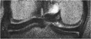
Figure 13-13. Discoid meniscus. Coronal T2-weighted image shows a rectangular (whale shaped) lateral meniscus demonstrating a discoid meniscus.
 Radiologic Findings—Internal Derangement of the Meniscus
The normal meniscus is homogeneously low in signal intensity on all sequences (Figure 13-14A,B). While all three planes should be evaluated, the sagittal plane is more valued and the anterior and posterior horns are wedge shaped, while the meniscus body has a bow tie appearance. For examining the integrity of the meniscus, reliance on T1- and intermediate-weighted PD spin echo with and without fat saturation images is favored over the T2 sequence. Imaging criteria for diagnosing meniscus tears include (1) abnormal intrameniscal signal that violates the surface of the meniscus and (2) abnormal morphology of the meniscus. With regard to abnormal intrameniscal signal, an MR grading system (Figure 13-15) based on cadaveric MRI and histologic correlation recognizes three grades of intrameniscal signal.14 As a rule of thumb, if the intrameniscal signal does not extend to the articular surface, then this does not meet the MRI criteria for a tear and is representative of intrasubstance degeneration. Rare notable exceptions that cause diagnostic difficulty include the “meniscus-within-meniscus” sign where there is extensive triangular or wedge-shaped intrasubstance signal that does not extend to the articular surface. This latter finding may represent a tear in up to 50% of menisci at arthroscopy and therefore is suggestive but not diagnostic of a tear.15 A similar presentation is seen in the setting of a meniscal contusion without a tear in the setting of acute injury that may be accompanied by an adjacent bone bruise.16 Alterations in the morphology of the meniscus that is diagnostic of a tear may include a blunted free edge, a normal triangular shape that is too small, and alteration in the meniscus contour. The meniscal root tear can be responsible for extrusion of the meniscus (Figure 13-16A–C). While no classification system is uniformly accepted for meniscus tears, proper nomenclature should be used and is based on commonly used lexicon that describes the direction and location of the tear (Figure 13-17). The most frequent type of tear is a “longitudinal tear” that propagates along the long or circumferential axis of the meniscus and is best identified in the sagittal plane, although all three planes should be evaluated. Longitudinal tears may be subcategorized as either “horizontal” or “vertical.” A horizontal tear separates the meniscus into an upper and lower portion (Figure 13-18A,B). The vertical tear separates the meniscus into a central portion and a peripheral portion (Figure 13-19A,B). Variations in this may be an oblique orientation and tears that may violate the superior surface, inferior surface, or both surfaces of the meniscus. Hence, tears may be described as longitudinal vertical, longitudinal horizontal, and longitudinal oblique. A “radial tear” is defined as a tear that begins at the inner margin of the meniscus-free edge and propagates outward for a variable distance, and if the radial tear is complete, it will divide the meniscus into an anterior and posterior portion (Figure 13-20A–C). This is most frequent in the middle third of the lateral meniscus. A variation of this is a “parrot beak” tear that is a combination of a radial tear with a longitudinal vertical component. Complex tears may have a multidirectional component. Tears may occur in the avascular white zone or in the vascularized red zone, the latter of which would provide an improved chance for healing. Furthermore, meniscal tears may result in fragments that are displaced, detached, flipped, or separated from the joint capsule. For example, displaced meniscus fragments or flap tears may reside in the medial or lateral joint gutter, may be displaced into the central weight-bearing aspect of the compartment, or toward the midline into the intercondylar notch. The extreme scenario is the “bucket handle” tear (Figures 13-21 and 13-22) in which there is central migration of a longitudinal vertical tear into the intercondylar notch with continuity of the central and peripheral portions of the torn meniscus at both the anterior and posterior margins of the tear.17 The term “bucket handle” describes the appearance of the torn meniscus, such that the inner displaced meniscal fragment resembles the handle, and the peripheral nondisplaced meniscal remnant represents the bucket. This pattern of tear is commonly seen in young people and presents with a history of locking and instability. There are a few imaging signs suggestive of a bucket handle tear, and these include the “absent bow tie sign” when fewer than two bow tie segments of the meniscus body are present on the sagittal sequence. The “flipped meniscus sign” (Figure 13-23) represents a torn and displaced meniscus fragment that resides directly on the anterior horn and produces an abnormally tall anterior horn.18 The “anterior horn sign” indicates a torn meniscal fragment that is displaced into the anterior compartment, and consequently, two anterior horns are visualized in the sagittal plane such that the anterior triangle represents the normal anterior horn and posterior triangle representing the displaced bucket handle fragment.19 The “double posterior cruciate ligament sign” (Figure 13-24) in the sagittal plane represents the displaced bucket handle fragment that lies inferior to the PCL. Corresponding coronal images also demonstrate the displaced bucket handle fragment as a “fragment in notch sign.”19,20 MRI of meniscal cysts that are associated with tears of the menisci are isointense to fluid on T2 (Figure 13-25) and intermediate proton density-weighted sequences. These may be homogeneous in signal intensity, or may contain internal and linear bands representing septa loculations within the cyst. Soft tissue edema may be observed in the tissues surrounding the meniscal cyst. When cysts are large, chronic subadjacent bone erosion may occur. Surgical treatment includes cyst decompression with either total or partial meniscectomy. Repair of a meniscus may also be performed with such material or biodegradable fixation devices. Recent advancements in surgical technique also include synthetic, autogenous, and allograft reconstructions.21,22 Follow-up MRI after meniscus repair is often performed; however, one should not apply the classic diagnostic criteria for a tear in the postoperative meniscus.23 Partial meniscectomy (Figure 13-26) shows a small truncated meniscus that may simulate a torn meniscus in a nonoperative knee. This is a consequence of a slow healing response to follow surgical repair, and there may be persistence of altered intrasubstance signal intensity within the repaired meniscus that is not diagnostic of a meniscal re-tear.24,25 In the postoperative meniscus, unless there is a displaced tear, the presence of fluid or administered contrast extending into substance of the meniscus is the most reliable MRI criteria to indicate a recurrent tear (Figure 13-27).26 The contour of the repaired meniscus can also be evaluated by MRI to determine if the meniscus is healed, partially healed, or demonstrates the failure of adequate healing exhibited by the size of a cleft at the site of repair (Figure 13-28). A cleft involving less than 10% of the entire width of the meniscus may be categorized as complete healing, while incomplete healing is demonstrated by a cleft that involves less than 50% of the entire width of the meniscus. A cleft greater than 50% indicates a failed repair.27 In either the preoperative or postoperative setting, internal derangement affecting the meniscus, cartilage, or ligaments may result in a synovial joint effusion. This effusion may communicate with an outpouching of the synovium in the posteromedial aspect of the knee situated between the medial head of the gastrocnemius and the semimembranosus, and this fluid collection is referred to as a popliteal or Baker cyst (Figure 13-29).
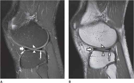
Figure 13-14. Normal meniscus. (A) Sagittal proton density fat-saturated and (B) sagittal T1 image demonstrates a normal-appearing lateral meniscus anterior horn (short fat arrow) and posterior horn (thin long arrow). Note the normal-appearing gray signal articular cartilage in the central weight-bearing lateral femoral condyle and lateral tibial plateau (triangles).
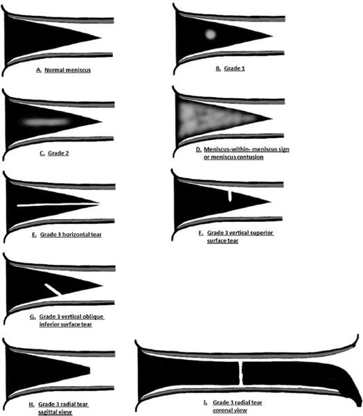
Figure 13-15. MR grading of intrasubstance meniscus signal and tears. (A) Normal meniscus with triangular wedge shape when viewed in the sagittal plane. The meniscus is homogeneous and dark in signal. (B) Grade 1 meniscus demonstrates mild intermediate intrasubstance signal degeneration without extension to the surface. (C) Grade 2 meniscus with a greater amount of intrasubstance degenerative signal without extension to the surface. (D) Meniscus-within-meniscus sign characterized by extensive “wedge-like” intrasubstance intermediate signal with near extension to the meniscus surface. Differential considerations may include an extensive intrasubstance degenerative signal with a possible tear or a meniscus contusion. (E) Grade 3 horizontal tear demonstrated by a horizontal band of signal with a cleavage-type appearance that extends to the free edge. (F) Grade 3 vertical tear that involves the superior surface of the meniscus. (G) Grade 3 vertical oblique tear that involves the inferior surface of the meniscus. (H, I) Grade 3 radial tear in the sagittal view characterized by a blunted free edge and in the coronal view demonstrated by a linear signal traversing through the meniscus substance. (From Resnick, D. In: Resnick DL, Kang HS, Pretterklieber ML, eds. Internal Derangements of Joints, 2nd edition. Philadelphia, PA: Elsevier/Saunders; 2006. Vol 2, Ch 25, with permission.)
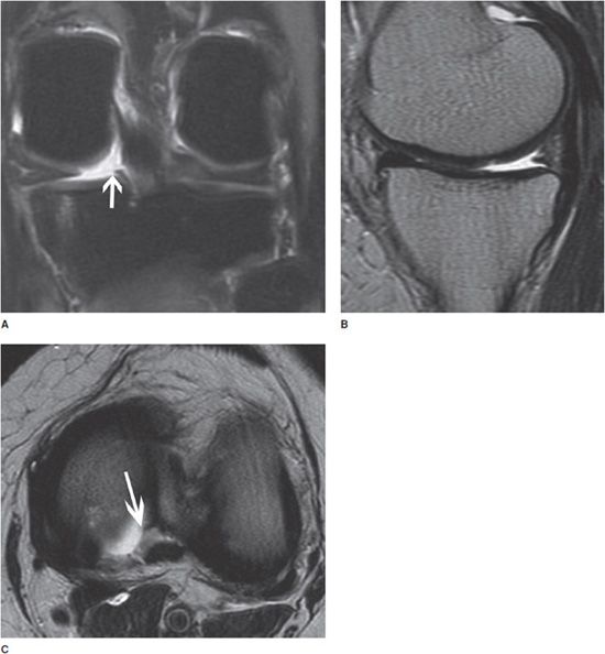
Figure 13-16. Meniscal root tear. (A) Coronal fluid-sensitive image shows the tear of the posterior root of the medial meniscus (arrow). (B) Sagittal T2-weighted image shows a small and truncated posterior horn of the medial meniscus suggesting a meniscal root tear. (C) Axial fluid-sensitive image shows a tear and fluid collection in the torn posterior root of the medial meniscus (arrow).
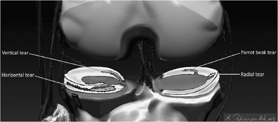
Figure 13-17. Descriptive lexicon of meniscus tears. Examples of the lexicon applied to various types of meniscus tears are illustrated in the medial compartment body by a “Radial” tear where the defect is along the radial axis of the meniscus similar to a spoke on a wheel. A variant of this is seen in the medial meniscus posterior horn where there is a “Parrot Beak” tear that is a combination of a radial tear at the free edge that turns into a vertical tear that propagates along the circumferential axis of the posterior horn. In the lateral compartment, a horizontal tear is present in the anterior horn that separates the meniscus into a superior and inferior half. In the inner aspect of the lateral meniscus posterior horn involving its tibial root attachment is a vertical tear that separates the meniscus into an inner half and an outer half.
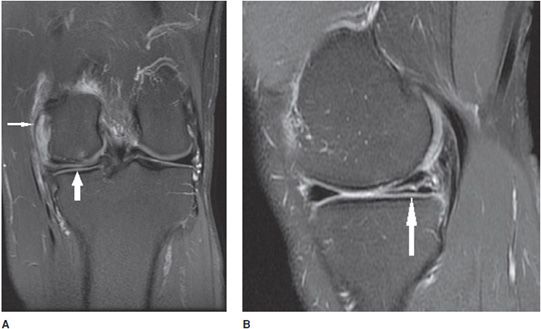
Figure 13-18. Horizontal meniscus tear. (A) Coronal proton density fat-saturated image demonstrates a linear fluid signal intensity in the meniscus (thick arrow). This horizontal tear propagates longitudinally through the posterior horn and the tear separates the meniscus into a superior and inferior half. Also note the small subchondral marrow edema in the medial femoral condyle and sprain of the MCL complex (thin arrow). (B) Sagittal proton density fat-saturated image in the same patient shows the horizontal tear involving the posterior horn from its peripheral red zone to its white zone-free edge (arrow).
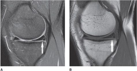
Figure 13-19. Vertical meniscus tear. (A) Sagittal proton density fat-saturated image shows a linear signal in the posterior horn of the medial meniscus involving the inferior surface indicating a vertical tear (arrow). (B) The vertical tear is corroborated on the sagittal T1 sequence.
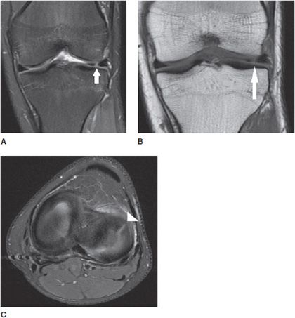
Figure 13-20. Radial meniscus tear. (A) Coronal proton density fat-saturated image shows a linear signal in the anterior aspect of the lateral meniscus (arrow) involving the body and anterior horn confluence indicating a radial tear. (B) Coronal T1 sequence corroborates the radial tear (arrow). (C) Axial proton density fat-saturated images in the plane of the meniscus demonstrate the tear as a linear band of fluid signal traversing through the meniscus like a spoke in a wheel. The white triangle shows the radial tear.
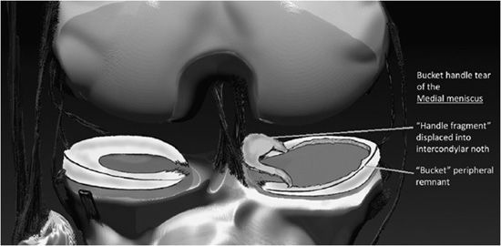
Figure 13-21. Bucket handle tear of the medial meniscus. Schematic of a bucket handle tear. The torn inner portion of the meniscus designated as the “bucket handle” is displaced toward the inner knee, where it resides in the intercondylar notch. The nondisplaced torn meniscus remnant located at the outer circumferential periphery of the medial compartment is termed the “bucket.”
Figure 13-22. Bucket handle tear. Coronal T2-weighted image shows a large fluid gap between the two meniscal fragments indicating a bucket handle tear of the meniscus. Note the large articular cartilage defect of the femoral condyle.
Figure 13-23. Bucket handle tear. Sagittal proton density image shows “flipped meniscus sign” indicating a bucket handle tear of the meniscus.
Figure 13-24. Bucket handle tear. Sagittal proton density image shows “double posterior cruciate ligament sign” indicative of a bucket handle tear of the meniscus.
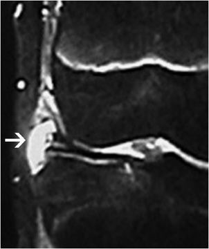
Figure 13-25. Meniscal cyst. Coronal fluid-sensitive image of the lateral meniscus showing a meniscal cyst (arrow) adjacent to a horizontal meniscal tear. (Image courtesy of Michael Recht.)
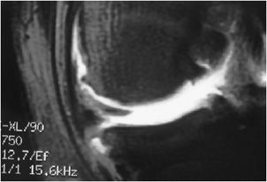
Figure 13-26. Partial meniscectomy. Coronal fat-saturated T1 MR arthrogram of the knee in a postoperative patient with previous meniscectomy shows a small and truncated meniscus due to the postmeniscectomy without presence of a re-tear. Image used with permission from Lee Katz.
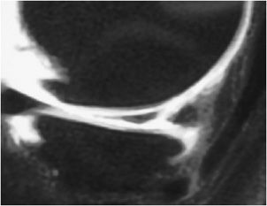
Figure 13-27. Postoperative re-tear. Coronal fat-saturated T1 arthrogram image shows contrast fluid gap between the two meniscal fragments indicating the re-tear of the meniscus. Image used with permission from Lee Katz.
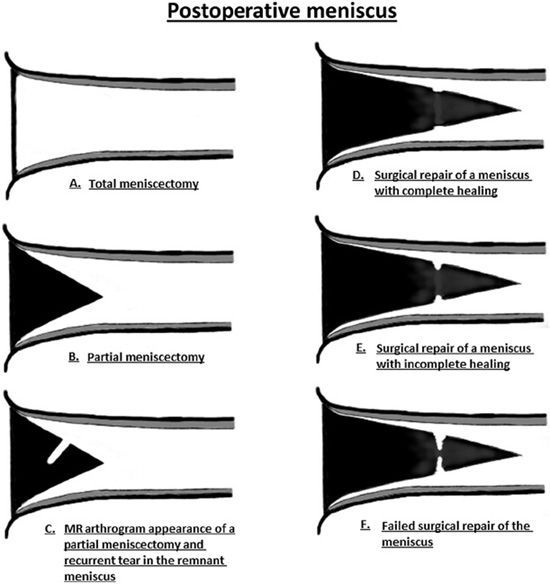
Figure 13-28. Imaging of the postoperative meniscus. (A) Total meniscectomy displayed as complete absence of the meniscus. (B) Partial meniscectomy shown as a diminutive size of the meniscus with a well-circumscribed contour. (C) MR arthrogram image in a partial meniscectomy is characterized by a linear line in the substance of the meniscus indicating contrast intrusion into the tear. (D) Surgical repair of a meniscus tear demonstrates a small cleft at the site of the tear but is less than 10% of the meniscus thickness. There is lack of contrast intrusion into the sutured portion indicating complete healing. (E) Incomplete healing in a surgically repaired meniscus characterized by a contrast-filled cleft that involves greater than 10% but less than 50% of the meniscus thickness. (F) Failed surgical repair of the meniscus demonstrated by a large contrast-filled cleft involving greater than 50% of the meniscus thickness. (From Resnick, D. In: Resnick DL, Kang HS, Pretterklieber ML, eds. Internal Derangements of Joints, 2nd edition. Philadelphia, PA: Elsevier/Saunders; 2006. Vol 2, Ch 25, with permission.)
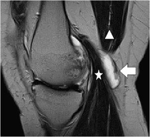
Figure 13-29. Baker cyst. Sagittal T2 sequence through the medial knee demonstrates a well-circumscribed oval fluid collection representing a Baker cyst (arrow) interposed between the medial head of the gastrocnemius (star) and the semimembranosus (triangle).
Related posts:
Stay updated, free articles. Join our Telegram channel

Full access? Get Clinical Tree


