The Spinal Cord and Vertebral Column
Mark C. Hollister
Arthur A. De Smet
M. C. Hollister and A. A. De Smet: Department of Radiology, University of Wisconsin Hospital and Clinics, Madison, Wisconsin 53792-3252.
The radiographic diagnosis of developmental, degenerative, neoplastic, infectious, and other conditions affecting the spinal cord and vertebral column are considered in this chapter. Imaging of the spine with radiographs, myelography, computed tomography (CT), magnetic resonance imaging (MRI), and angiography are discussed.
ANOMALIES OF THE SPINAL COLUMN
Embryology of the Vertebrae
Familiarity with the embryology of the spine is critical to understanding congenital anomalies. The notochord is the column of cells derived from the endoderm around which the vertebrae develop. During the early weeks of embryonic life, the notochord forms a long, rounded column extending from the hypophyseal pouch to the lower end of the primitive spine. The mesenchyme surrounding the notochord undergoes segmentation with the formation of zones of densely packed cells, called sclerotomes, separated by less dense zones. The sclerotomes develop regions that form the anlagen for the vertebral bodies, the neural arches, the transverse processes, and the ribs. Eventually the notochord is completely surrounded by the regions arising from the sclerotomes, and the primitive vertebrae are formed. With further development, the notochord becomes squeezed into the regions that will become the intervertebral discs. The anlage for the vertebral body is divided initially into two lateral halves by an extension of the perichordal sheath. Centers of chondrification begin on either side of the sheath. The cartilage centers fuse but, for a time, there is left a remnant of the sheath in the center of the cartilaginous vertebral body, known as the mucoid streak. This is continuous with the remnants of notochord that come to lie within the disc regions.
Ossification of the vertebral body begins from two separate centers at 3½ to 4 months of fetal life. These do not correspond to the two centers of chondrification already mentioned but rather are situated dorsally and ventrally. Shortly after their fetal appearance, they fuse to form a single center for each vertebral body. The neural arch ossifies from two centers, one for each lateral half. At birth the vertebra consists of three separate ossification areas, one for the body and two for the arch; these are separated by zones of cartilage. Shortly after birth, the two halves of the neural arch unite, beginning first in the lumbar area and ascending to the cervical area. Union of the arches to the bodies begins during the third year of life and is completed by about the seventh year. This fusion begins in the cervical region and is completed in the lumbar region. At the time of puberty, secondary ossification centers appear for the tips of each of the vertebral processes, and a ring-like epiphyseal plate for the upper and lower edges of the bodies also begins to ossify (Fig. 12-1).
 FIG. 12-1. Normal vertebral “ring” epiphysis. Lateral view of the midthoracic spine in an adolescent. |
Embryology of the Intervertebral Disc
The masses of notochordal cells between the vertebrae, with the addition of mucoid material, fibrous tissue, and hyaline cartilage cells, form the nucleus pulposus of the fully developed intervertebral disc. Notochordal cells can be identified in the nucleus until adolescence or even later. During early life and until the age of 25 to 30 years, the nucleus pulposus forms a semifluid, noncompressible substance that is important in absorbing shocks and in distributing the stresses to which the spine is subjected. During the period of its development, the intervertebral disc is supplied by blood vessels derived from the periosteum and by vessels extending into the disc from the vertebral bodies. The latter penetrate the cartilage plate surrounding the nucleus pulposus. Shortly after birth, these vessels regress and disappear.
Where the vessels penetrated the cartilage plates of the disc, defects in chondrification result, and these may persist throughout life.
Notochordal Lesions: Chordoma and Schmorl’s Nodes
Although the remnants of notochord enclosed within cartilage disappear as the disc becomes avascular, there are areas where small masses of fetal notochord may persist throughout life. These are found most frequently in the region of the clivus at the base of the skull and in the sacrococcygeal area. It is in these locations that a tumor known as chordoma is prone to develop. Chordoma is a malignant neoplasm that seldom metastasizes but is very invasive locally.
Remnants of notochord sometimes persist where the mucoid streak entered the disc. These are visible radiographically as smooth, cup-shaped or concave impressions in the end-plates of one or more vertebral bodies. Usually the defects are multiple, and they are seen most frequently in the lower thoracic and upper lumbar spine. These notochordal defects are areas through which protrusion of disc material into the vertebral body may occur. These herniations of disc material are known as Schmorl’s nodes (Fig. 12-2). Schmorl’s nodes are a common disc abnormality, with a prevalence of almost 20% on MRI studies.31 Although they usually are considered to be incidental findings, they may on occasion be symptomatic.
 FIG. 12-2. Schmorl’s node. Lateral lumbar radiograph demonstrates multiple concave impressions in the vertebral end-plates, caused by intravertebral protrusion of disc material. |
As noted previously, gaps in chondrification of the disc are formed by vessels arising from the vertebral body. These weak areas predispose to traumatic intravertebral protrusion of disc material. When the herniated material is composed only of cartilage, the defect may be difficult or impossible to visualize on radiographs. Usually, with time, reactive sclerosis forms around the herniated cartilage nodule and it becomes visible. These traumatic Schmorl’s nodes usually occur near the center of the disc surface of the body, but they may be situated eccentrically. The defect is concave, and the wall of sclerosis is distinct. Thinning of the intervertebral disc space may or may not accompany herniation of disc material. Thinning of the disc in these patients is caused not so much by the actual herniation of disc material but by disc desiccation, which may either precede or follow the herniation. With degeneration, the disc loses turgor and elasticity, and its total volume is reduced.
Vertebral Fusion Anomalies
Fusion or partial fusion of two or more vertebral bodies occurs occasionally. Usually such congenital fusion can be differentiated from that resulting from disease by the fact that the sum in height of the congenitally fused bodies is equal to the normal height of two vertebrae plus the expected height of an intervertebral disc if one were present. Often, there is a slight “hourglass” configuration to the compound vertebra, caused by remodeling at the fused disc space. The bony structure of the fused vertebra is normal except for the fusion. In cases of partial fusion, it is normally the anterior aspect that fuses, while a rudiment of the disc remains in the posterior portion (Fig. 12-3). Clinical symptoms ordinarily are not associated with vertebral fusion except in atlanto-occipital fusion and in Klippel-Feil syndrome.
 FIG. 12-3. Congenital fusion of two lumbar vertebrae (“block vertebra”). Note concavity of the anterior vertebral contour at the level of the expected disc space (not seen in surgical fusions) and the posterior remnant of the intervertebral disc. |
Klippel-Feil syndrome is an extensive fusion of multiple cervical spinal segments.45 There is numeric variation in the
cervical vertebrae, with either complete fusion into one bony mass or multiple irregular ossified segments. The upper thoracic vertebrae may be affected in the same way, and there often are neural arch closure defects as well as other skeletal anomalies. The classic physical signs include shortening of the neck, a lowering of the hairline on the back of the neck, and limitation of motion of the head.61 Klippel-Feil syndrome is often associated with congenital elevation and medial rotation of the scapula (Sprengel’s anomaly) and with cardiovascular and genitourinary anomalies.
cervical vertebrae, with either complete fusion into one bony mass or multiple irregular ossified segments. The upper thoracic vertebrae may be affected in the same way, and there often are neural arch closure defects as well as other skeletal anomalies. The classic physical signs include shortening of the neck, a lowering of the hairline on the back of the neck, and limitation of motion of the head.61 Klippel-Feil syndrome is often associated with congenital elevation and medial rotation of the scapula (Sprengel’s anomaly) and with cardiovascular and genitourinary anomalies.
Hemivertebra and Butterfly Vertebrae
Failure or incomplete development of a lateral half of a vertebral body results in a lateral hemivertebra. Embryologically, the fault probably lies in failure of development of one of the lateral centers of chondrification. A hemivertebra has a triangular shape when viewed in the anteroposterior (AP) radiograph; it causes scoliosis with an acute lateral angulation of the spine. A hemivertebra in the thoracic region has only one rib, which is on the side of the ossified center. Associated with a hemivertebra there may be numeric variations in the ribs, fusion of two or more ribs, and rudimentary development of other ribs. Except for the scoliotic deformity that it causes, a hemivertebra usually results in no clinical symptoms (Fig. 12-4).
 FIG. 12-4. Congenital hemivertebrae in the thoracic spine of an infant. Three adjacent hemivertebrae are noted (arrow), as is an associated convex rightward scoliosis. |
A dorsal hemivertebra probably occurs because of failure of development of the ventral fetal ossification center. This anomaly often causes a progressive kyphosis that may require posterior fusion at the level of the hemivertebra. A ventral hemivertebra caused by failure of development of the dorsal ossification center is rare.
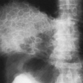
Occasionally the two lateral centers of chondrification for a vertebral body fail to fuse, and a cleft persists in the midsagittal plane, dividing the body into two lateral halves. More frequently the cleft is only partial, resulting in a characteristic shape that is described as a “butterfly vertebra” (Fig. 12-5).
 FIG. 12-5. “Butterfly vertebra.” A: Anteroposterior radiograph of a partial sagittal cleft of the 10th thoracic vertebra. B: Computed tomographic image demonstrates the axial appearance of a butterfly vertebral body. |
Spinal Dysraphism
Spinal dysraphism is the general term for the spectrum of neural tube closure defects, ranging from minor posterior element bony defects to large myelomeningocoeles.19 Patients with spinal dysraphism may also have a tethered conus, diastematomyelia, or intradural lipomas. MRI is the procedure of choice for assessing the extent of the spinal anomalies.9,50
The presence of a vertical cleft or ossification defect in the midline of a posterior neural arch is common in the lumbosacral region and other transitional areas in the spine. This condition is known as spina bifida cystica when there are associated soft-tissue defects or a meningocele, and spina bifida occulta when no soft-tissue malformation exists. Spina bifida occulta is most frequent in the axis (C1), first thoracic vertebra, fifth lumbar vertebra, and first sacral segment.
Spina bifida occulta generally has no clinical significance.
Spina bifida occulta generally has no clinical significance.
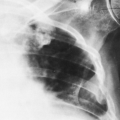
Lumbosacral meningoceles are usually associated with spinal dysraphism. Most intrathoracic meningoceles occur in association with neurofibromatosis, are on the right side, and may appear as an intrathoracic posterior mediastinal mass. They often enlarge the intervertebral foramen and therefore may be mistaken for neurofibromas on radiographs. Communication with the subarachnoid space demonstrated on myelography or MRI confirms the diagnosis of an intrathoracic meningocele. Rarely, anterior herniation through a sacral defect results in an anterior sacral meningocele. A pelvic mass in conjunction with partial or total sacral agenesis suggests the diagnosis, which can be confirmed by MRI. Meningocele must be differentiated from teratoma in this instance.
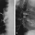
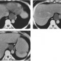
Diastematomyelia is a rare anomaly of the spine, consisting of a vertical division of the spinal cord or the cauda equina, the two portions usually being separated by a fibrous, cartilaginous, or osseous septum (Fig. 12-6). This septum is attached anteriorly to one or more of the vertebral bodies. Diastematomyelia is found most frequently in the lumbar spine, less commonly in the thoracic region. The lesion is clinically significant, because the patient eventually will show evidence of impaired innervation to the lower extremities. Dimpling of the skin, local pigmentation, or excessive hair may be present over the area of the diastematomyelia at birth. Occasionally there is an associated meningocele. Diastematomyelia is much more common in girls, with only 15% of cases reported in boys.9 Radiographs of the spine show widening of the interpediculate distances over several segments and, often, a fusion or partial fusion of vertebral bodies. Other commonly associated abnormalities include kyphosis, scoliosis, spina bifida, hemivertebrae, abnormal fusion of laminae, and narrowing of intervertebral spaces. If the septum dividing the cord is ossified, it may be visualized on AP radiographs as a vertical, thin, bony plate lying in
the midline of the neural canal. CT scanning with intrathecal contrast medium or MRI can be used to define the septum and divided spinal cord.
the midline of the neural canal. CT scanning with intrathecal contrast medium or MRI can be used to define the septum and divided spinal cord.
 FIG. 12-6. Axial computed tomographic scan after intrathecal contrast injection shows diastematomyelia with central bony septum (large arrowhead) dividing the dural sac and conus medullaris (small arrowhead) into two parts. (Courtesy of Patrick Turski, M.D., Madison, WI) |
A tethered conus is a congenital anomaly with a low position of the conus, held in a posterior position. External signs of spinal dysraphism, including hypertrichosis, subcutaneous lipoma, dermoids, and sinus tracts, are present in about one half of these patients. Intradural abnormalities such as lipomas, dermoids, and widening of the dural sac were found in 10 of 24 patients reported by Fitz and Harwood-Nash.22 These anomalies are well defined by MRI.
Sacral Agenesis (Caudal Regression Syndrome)
Absence of part or all of the sacrum is an uncommon anomaly that is usually associated with maternal diabetes.33 There is a high incidence of neurogenic bladder in these infants, with the complications of vesicoureteral reflux, hydronephrosis, and infection. Occasionally, patients with agenesis of the sacrum have a severe neurologic deficit below the level of the spinal anomaly. The changes associated with sacral agenesis have been termed the caudal dysplasia syndrome or caudal regression syndrome.25 In addition to neurogenic bladder, there may be abduction and flexion deformities of the lower extremities with popliteal webbing so that the legs cannot be straightened. In severe cases, the lower extremities may be fused (sirenomelia).
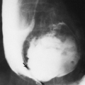
The radiographic findings are dramatic in severe cases with absence of the sacrum (Fig. 12-7). In less advanced cases, only the distalmost segments of the sacrum are absent. Most patients have an equinovarus deformity of the feet and, less frequently, dislocation of the hips. The upper extremities usually are normal. Sacral agenesis is often associated with imperforate anus and cloacal malformations. MRI is recommended for assessment of these patients.19
 FIG. 12-7. Anteroposterior pelvis radiograph of severe caudal regression syndrome. The sacrum and lower lumbar vertebrae are absent. Secondarily, the ilia are drawn toward the midline. |
Failure of Fusion of Secondary Ossification Centers
Secondary ossification centers appear normally at the tips of all the spinous and transverse processes; occasionally one or more of these fail to unite and persist into adult life as a separate bony fragment.
A small, triangular bony mass may be found at the tip of one or more of the inferior articular processes of the vertebrae. This represents a nonunited ossification center, and it can be confused with a fracture. The smooth corticated margins of the fragment help differentiate this anomaly from an acute fracture (Fig. 12-8). A similar center occasionally is seen for the superior articular process but is much less common.
 FIG. 12-8. Oblique lumbar spine radiograph showing a nonunited apophysis (white arrow) of the L4 inferior articular process. The smooth, sclerotic margins indicate that this is not an acute fracture. |
Anterior interposition of herniated nuclear material may prevent fusion of a portion of the peripheral ring apophysis with the adjacent vertebral end-plate. On lateral radiographs, this results in a triangle-shaped bony mass along the anterosuperior corner with a corresponding defect in the adjacent vertebral body and is known as a limbus vertebra (Fig. 12-9). This developmental phenomenon has been confirmed at MRI and is in the spectrum of intravertebral disc herniation, which includes Schmorl’s nodes.
 FIG. 12-9. Limbus vertebra. An nonunited accessory ossification center of the anterosuperior corner of the fourth lumbar vertebra is shown. The smooth bony margins and characteristic shape and location of this variant should prevent its being mistaken for a fracture. Limbus vertebrae are most commonly seen in the lumbar spine. |
Transitional Vertebra
At the junctions of the major divisions of the spine, a vertebra may take on part of the characteristics of both divisions. This most frequently occurs at the thoracolumbar and lumbosacral junctions. The first lumbar, and rarely the second, may have rudimentary ribs articulating with the transverse processes. The fifth lumbar vertebra may be partially sacralized, often with one transverse process fused with the sacrum, the other being free, and with only a rudimentary disc between them (Fig. 12-10). The first sacral segment may become partially lumbarized in the same manner. When the transition is complete, there may be 6 lumbar vertebrae and 4 sacral segments, or 13 thoracic and 4 lumbar, or various combinations. Usually, an addition of a segment to one division of the spine is corrected at another level. When
surgery is being considered for a disorder of the spine (e.g., herniated disc), it is critical that communication of the level of the abnormality is accurate and consistent. This may be a problem when thoracic and lumbar MRI studies are used to assign vertebral level without benefit of radiographs, because transitional vertebrae are more difficult to identify. One study of lumbar MRI found incorrect assignment of vertebral levels in 20% of cases.49
surgery is being considered for a disorder of the spine (e.g., herniated disc), it is critical that communication of the level of the abnormality is accurate and consistent. This may be a problem when thoracic and lumbar MRI studies are used to assign vertebral level without benefit of radiographs, because transitional vertebrae are more difficult to identify. One study of lumbar MRI found incorrect assignment of vertebral levels in 20% of cases.49
 FIG. 12-10. Transitional vertebra. The fifth lumbar vertebra is partially sacralized. Its left transverse process is enlarged and articulates with the sacrum. The right L5 transverse process is free. |
The seventh cervical vertebra may have unilateral or bilateral ribs attached to its transverse processes. These cervical ribs may be only short structures or they may be long enough to articulate with the sternum. A cervical rib may be fused with the first thoracic rib, or it may form a pseudarthrosis with it. As the cervical rib passes anteriorly, it may compress the subclavian vessels, causing venous thrombosis or arterial insufficiency. Even when the cervical rib is short, a fibrous band may extend from its tip to the first rib or to the sternum and be a source of compression of a subclavian vessel.
Pedicle Anomalies
Absence or hypoplasia of a pedicle is occasionally observed in the cervical spine. Absence of a lumbar pedicle with compensatory hypertrophy of the opposite pedicle has been reported but is rare. The hypertrophy of the opposite lumbar pedicle differentiates this anomaly from a destructive lesion of a pedicle (Fig. 12-11). With an absent pedicle, the ipsilateral intervertebral foramen is widened, and there is posterior displacement of the maldeveloped lateral mass. Absence or hypoplasia of a pedicle must be differentiated from erosions caused by neurofibromatosis, primary tumors, metastases, or arch fractures.
 FIG. 12-11. Anteroposterior radiograph of the upper lumbar spine. The right pedicle of L2 is absent (white arrow). The left pedicle of L2 shows compensatory sclerosis and hypertrophy. |
Flattening or thinning of a pedicle at the 12th thoracic or 1st lumbar level, either unilaterally or bilaterally, is a common anatomic variant.3 The inner cortical margin may be straight, convex, or concave, and the outer margin may be flat or concave.
DEGENERATIVE DISEASE
Back pain is ubiquitous in our society; the lifetime prevalence of low-back pain alone approaches 80%.53 Neck and back pain are often related to degenerative changes in the
spine. Modern imaging techniques, especially MRI, accurately depict both normal and degenerative morphology of the spine. However, there is an inconsistent correlation between degenerative anatomic abnormalities and symptomatology.4,31 A sizable minority (25%) of asymptomatic people have small lumbar disc protrusions visible on MRI. Conversely, some patients with significant, even disabling, clinical symptoms have minimal anatomic abnormalities on MRI. Careful consideration of the history, the physical examination, and the results of other diagnostic tests is required before clinical significance can be attributed to the morphologic changes depicted on imaging examinations. Still, the unique anatomic information that modern imaging techniques provide has greatly contributed to the understanding of spinal disease and will continue to influence diagnosis and treatment decisions.
spine. Modern imaging techniques, especially MRI, accurately depict both normal and degenerative morphology of the spine. However, there is an inconsistent correlation between degenerative anatomic abnormalities and symptomatology.4,31 A sizable minority (25%) of asymptomatic people have small lumbar disc protrusions visible on MRI. Conversely, some patients with significant, even disabling, clinical symptoms have minimal anatomic abnormalities on MRI. Careful consideration of the history, the physical examination, and the results of other diagnostic tests is required before clinical significance can be attributed to the morphologic changes depicted on imaging examinations. Still, the unique anatomic information that modern imaging techniques provide has greatly contributed to the understanding of spinal disease and will continue to influence diagnosis and treatment decisions.
Methods of Examination
Routine Radiography
Although radiographs of the spine are frequently obtained in the evaluation of back pain, most episodes of back pain are self-limited and do not require imaging. Concern regarding the potential overutilization of plain film radiography led the American College of Radiology and other organizations to recommend that lumbar spine radiographs not be obtained for acute low-back pain unless specific clinical risk
factors for fracture, malignancy, or infection are present.12,62 When radiography is warranted, AP and lateral projections usually suffice. Oblique views of the lumbar spine may identify a nondisplaced spondylolysis that is obscured by superimposition in the lateral projection. In the cervical spine, oblique views are often helpful because they provide unobstructed views of the neural foramina, which may be narrowed by osteophytes (Fig. 12-12). On rare occasions flexion and extension views are warranted, usually in the setting of subacute trauma or in presurgical patients in whom evidence of instability is sought.
factors for fracture, malignancy, or infection are present.12,62 When radiography is warranted, AP and lateral projections usually suffice. Oblique views of the lumbar spine may identify a nondisplaced spondylolysis that is obscured by superimposition in the lateral projection. In the cervical spine, oblique views are often helpful because they provide unobstructed views of the neural foramina, which may be narrowed by osteophytes (Fig. 12-12). On rare occasions flexion and extension views are warranted, usually in the setting of subacute trauma or in presurgical patients in whom evidence of instability is sought.
 FIG. 12-12. Normal cervical spine. A: Lateral view demonstrates normal vertebral body alignment and intervertebral disc spaces. Lateral articular masses and facet joints project over the normal spinal canal. The foramina project anterolaterally and are not visible. B: The 45° anterior oblique view looks down the barrel of the widely patent nerve root foramina. Hypertrophy of either the facet joints (arrows) or uncinate processes (arrowheads) may encroach on the nerve roots as they traverse the foramina. |
Myelography
Myelography entails injection of iodinated contrast material within the thecal sac to render it and the enclosed neural structures visible by radiography or CT scanning.56 Mixed with cerebrospinal fluid (CSF), contrast material outlines the surfaces of the spinal cord, intrathecal nerve roots, thecal sac borders, and any abnormal masses or extrinsic impressions. Before the development of CT and MRI, myelography was the primary tool for radiologic diagnosis of intradural pathology and spinal stenosis. Today, myelography is usually used for problem solving. The most common current indications for myelography are when there are contraindications to MRI, when MRI findings are equivocal or images suboptimal (e.g., extensive spinal hardware, obesity), and when detailed bony evaluation is required in addition to soft-tissue information.
To perform a myelogram, a 22-gauge (or thinner) spinal needle is used for lumbar puncture, and contrast material is injected under fluoroscopic control to ensure subarachnoid placement. To minimize the risk of side effects, a nonionic contrast medium is used. The volume and concentration of contrast material employed depend on the site being studied, the route of delivery, physician preference, and whether CT will be performed after the myelogram. For cervical myelography, contrast material may be deposited in the lumbar thecal sac and shifted cranially by gravity (iodinated contrast has a higher specific gravity than CSF) or by way of a carefully monitored lateral C1-C2 puncture, targeting the posterior third of the spinal canal32 (Fig. 12-13). After injection
of the contrast medium, AP, lateral and oblique radiographs of the desired spinal segments are obtained (Figs. 12-14 and 12-15). CT scanning frequently follows the plain film myelogram, greatly adding to the diagnostic utility of the examination (Fig. 12-16).
of the contrast medium, AP, lateral and oblique radiographs of the desired spinal segments are obtained (Figs. 12-14 and 12-15). CT scanning frequently follows the plain film myelogram, greatly adding to the diagnostic utility of the examination (Fig. 12-16).
 FIG. 12-13. C5-C6 disc herniation identified by cervical myelogram after posterior C1-C2 puncture. Shallow oblique frontal projection shows amputation of the C5-C6 axillary root sleeve, compression of the contrast column, and slight displacement of the spinal cord (arrow). |
 FIG. 12-14. Normal lumbar myelogram, lateral projection. The contrast-filled lumbosacral thecal sac has a smooth ventral contour. Descending nerve roots are visible as linear, obliquely oriented filling defects. Note the wide ventral epidural space between the contrast-filled thecal sac and posterior vertebral margin (arrowheads) which is greatest at the lumbosacral junction. Small disc herniations into this region may be invisible at myelography. |
 FIG. 12-15. Lumbar myelograms, oblique views. A: Oblique projection in a normal myelogram shows symmetric caliber and course of the exiting lumbar roots and good filling of all axillary root sleeves. B: Opposite oblique in a different patient with paracentral disc herniation shows displacement and flattening of the exiting S1 nerve root and nonfilling of its axillary root sleeve (arrow). The upper lumbar roots are normal. |
 FIG. 12-16. Postmyelogram computed tomographic scan shows central disc herniation. An image at the level of the lumbosacral disc shows abnormal soft tissue (higher density than fat) in the ventral epidural space (arrowheads) which effaces the anterior aspect of the thecal sac and slightly displaces the right S1 nerve root. |
Computed Tomography (CT)
CT scanning is an excellent technique for evaluating the bony spinal canal as well as certain intraspinal soft-tissue structures11,28,29 (Fig. 12-17). In cases of degenerative disease in which bone contributes significantly to compression of the spinal cord or nerve roots, CT can be more useful than MRI, because MRI has difficulty resolving desiccated disc material from bony structures and also tends to artifactually overestimate the degree of stenosis caused by hypertrophic bone.5 Standard CT techniques call for obtaining contiguous, thinly collimated axial or oblique axial slices through the involved segment of the spine. Varying the plane of sectioning to parallel that of each disc individually is not recommended because it hinders multiplanar reformatting and can result in missed diagnoses if portions of the spinal canal are not imaged because of failure to overlap slices. For example, one study found that spondylolysis was missed in 8 of 8 cases when scanning was done parallel to the disc spaces only.24 To reduce loss of spatial resolution caused by partial volume averaging, 3-mm collimation is recommended; 1- to 2-mm collimation is frequently used in the upper cervical spine. Helical scanning of the spine is feasible but is sometimes limited by tube heating. Sagittally reformatted images are essential to assess vertebral alignment and provide a second plane for estimating the amount of extruded disc material26 (Fig. 12-18). Images are filmed in both bone (wide window) and soft-tissue (narrow window) settings.
 FIG. 12-17. Normal lumbar computed tomographic images. A: Axial image through the midportion of the L4 vertebral body demonstrates typical appearance of the spinal structures, including pedicles (P), transverse processes (black arrows), spinous process (S), facet joints (curved arrows), ligamentum flavum (arrowheads), thecal sac (TS), and posterior epidural fat (white arrow). Slightly higher-density soft tissue ventral to the thecal sac represents the posterior longitudinal ligament and epidural veins. B: Slightly more inferior slice through the L4-L5 disc space. Notice the slightly higher density of the intervertebral disc (arrowheads) relative to that of the intrathecal cerebrospinal fluid and epidural fat. |
 FIG. 12-18. Sagittally reformatted lumbar computed tomographic scan. Midsagittal image shows normal contour of the L3-L4 disc, a small central disc protrusion at L4-L5, and a larger, inferiorly projecting disc extrusion at L5-S1. Note mild displacement of the posterior longitudinal ligament (arrowheads). |
With the addition of intrathecal contrast, the accuracy of CT for degenerative conditions in the spine approaches that of MRI,64 but disadvantages such as the inability to directly image the spine in planes other than axial; the use of ionizing radiation; and the possibility of spinal headache, infection, or contrast reaction associated with myelography are not insignificant. Moreover, although disc displacements can usually be accurately detected with CT, more specific categorization (e.g., protrusion versus extrusion) and assessment
of mass effect on adjacent neural structures are more accurately determined by MRI.41 Tears of the disc annulus are not visible on CT but are easily diagnosed with MRI.
of mass effect on adjacent neural structures are more accurately determined by MRI.41 Tears of the disc annulus are not visible on CT but are easily diagnosed with MRI.
Magnetic Resonance Imaging
MRI provides noninvasive, directly multiplanar and highly accurate anatomic images of spinal structures, making it the leading imaging modality for many applications.39,44,48 MRI detects degenerative changes within discs earlier than CT and is more accurate and more reproducible than CT in classification of disc herniations. With the addition of intravenous gadolinium, MRI is particularly useful to differentiate enhancing postoperative scar from nonenhancing recurrent or residual disc material in patients who have had disc surgery6,54 (Fig. 12-19).
 FIG. 12-19. Large L4-L5 disc extrusion diagnosed by magnetic resonance imaging in a 62-year-old woman 15 years after an L5-S1 discectomy. Sagittal (A) and axial (B) fast spin-echo T2-weighted images through the lumbosacral spine demonstrate a large ventral epidural mass that follows the signal intensity of the nucleus pulposus. The extruded material extends behind the L5 vertebral body in the left lateral recess, displacing the thecal sac and contacting the descending left S1 nerve root (arrowheads). Sagittal T1-weighted precontrast (C) and postcontrast (D) images further confirm that the extruded material follows the L4-L5 disc in signal intensity and is contiguous with the L4-L5 disc space. Note the peripheral epidural enhancement around the extruded disc material (arrowheads) as well as the posterior enhancement of the operative defect at L5-S1 (white arrow). There is no evidence of recurrent herniation at the L5-S1 level. |
Optimal diagnostic accuracy requires the use of proper imaging protocols and surface coils. Typical protocols include sequences in both sagittal and axial planes. In the lumbar spine, sagittal T1-weighted and multi-echo fast spin-echo (FSE) T2-weighted sequences are commonly employed. In the axial plane, axial T1-weighted or multi-echo FSE T2-weighted images are used most often in the lumbar spine, and gradient-echo images (two- and three-dimensional) are most commonly employed in the cervical spine. T2-weighted images provide a myelographic effect (CSF bright, neural tissue dark), allowing accurate evaluation of the cord and nerve roots within the thecal sac. T2-weighted sequences also allow early detection of disc degeneration, which appears as a loss of signal intensity within the nucleus pulposus. Many prefer proton density–weighted images for the
evaluation of disc margins because they provide sharp contrast between the posterior aspect of the disc and the adjacent thecal sac and posterior longitudinal ligament. T1-weighted images are useful in evaluation of the discs but also provide valuable information regarding the marrow space of the vertebrae. Replacement of the predominantly fatty tissue of normal marrow by tumor, inflammatory cells, blood, or calcification results in a change in signal intensity within the vertebra from white to gray or black (Fig. 12-20). When more sensitive marrow imaging is required, fat-suppression imaging is frequently employed. Fast spin-echo short tau inversion recovery FSE-STIR and FSE T2-weighted sequences with frequency-selective fat suppression, available on most MRI systems, are excellent for this purpose (Fig. 12-21). Because of the small size of the structures being evaluated, slice thickness and interslice gap should be minimized on all pulse sequences. Most protocols utilize a slice thickness of 3 or 4 mm and an interslice gap of 1 mm or less. Epidural and paravertebral fat provide natural contrast with adjacent bony and neural structures on T1-weighted sequences but may reduce conspicuity of enhancement after introduction of intravenous gadolinium. Therefore, many centers favor fat suppression for postcontrast T1-weighted imaging.
evaluation of disc margins because they provide sharp contrast between the posterior aspect of the disc and the adjacent thecal sac and posterior longitudinal ligament. T1-weighted images are useful in evaluation of the discs but also provide valuable information regarding the marrow space of the vertebrae. Replacement of the predominantly fatty tissue of normal marrow by tumor, inflammatory cells, blood, or calcification results in a change in signal intensity within the vertebra from white to gray or black (Fig. 12-20). When more sensitive marrow imaging is required, fat-suppression imaging is frequently employed. Fast spin-echo short tau inversion recovery FSE-STIR and FSE T2-weighted sequences with frequency-selective fat suppression, available on most MRI systems, are excellent for this purpose (Fig. 12-21). Because of the small size of the structures being evaluated, slice thickness and interslice gap should be minimized on all pulse sequences. Most protocols utilize a slice thickness of 3 or 4 mm and an interslice gap of 1 mm or less. Epidural and paravertebral fat provide natural contrast with adjacent bony and neural structures on T1-weighted sequences but may reduce conspicuity of enhancement after introduction of intravenous gadolinium. Therefore, many centers favor fat suppression for postcontrast T1-weighted imaging.
 FIG. 12-20. Thoracic vertebral metastasis. Sagittal T1-weighted image shows that the normally bright signal of the fatty marrow of a single vertebra has been completely replaced by tumor of intermediate signal intensity. Extension of tumor into the spinal canal is apparent, with compression of the spinal cord. |
 FIG. 12-21. Liposarcoma of the thigh, metastatic to the lumbar spine. Low-signal-intensity marrow in the L4 and L5 vertebral bodies and a ventral epidural soft-tissue mass of similar signal intensity at L5 are apparent in the T1-weighted image (A) but much more conspicuous with FSE-STIR (B). The L3-L4 and L4-L5 discs are degenerated, but the inversion recovery image clearly excludes disc as the source of the epidural soft-tissue mass (unlike the case shown in FIG. 12-19). Additional sacral metastases are also identified with STIR images. |
Disc Disease
Degeneration
Intervertebral discs consist of a central nucleus pulposus encircled by a strong annulus fibrosis. The nucleus pulposus is a dense gel of proteoglycans, collagen fibers, and water hydrophilically bound to macromolecules. The annulus consists of 15 to 20 concentric lamellae of collagen bands, the outer layers of which are tightly bound to the adjacent vertebral end-plates.40 The earliest degenerative changes in discs are thought to be cracks or fissures in the inner layers of the annulus fibrosus. Concomitant alterations in the proteoglycan matrix of the nucleus pulposus results in loss of bound water molecules. This dehydration is associated with a loss
of disc height, reflecting the diminished turgor and elasticity of the dehydrated nucleus pulposus. Decreased capacity for shock absorption in degenerated discs allows greater forces to be transmitted directly onto adjacent vertebral bodies. This stimulates the formation of vertebral osteophytes and the end-plate edema and sclerosis often identified with degenerated discs.
of disc height, reflecting the diminished turgor and elasticity of the dehydrated nucleus pulposus. Decreased capacity for shock absorption in degenerated discs allows greater forces to be transmitted directly onto adjacent vertebral bodies. This stimulates the formation of vertebral osteophytes and the end-plate edema and sclerosis often identified with degenerated discs.
Radiographs become abnormal in later stages of disc degeneration, beginning with loss of disc-space height. Normal cervical and thoracic discs are almost equal in height. Normal lumbar discs progressively increase in height from T12-L1 through L4-L5, the L5-S1 disc having a variable height because of its transitional status. Therefore, isolated loss of height at any one disc space is usually indicative of early degeneration. Degenerative changes progress to include osteophyte formation at the periphery of vertebral end-plates, end-plate sclerosis, and malalignment (scoliosis, retrolisthesis, anterolisthesis). Not uncommonly, gas is visible within markedly degenerated discs. This is thought to represent nitrogen gas drawn from the blood by the negative pressure generated in extension within the airtight degenerated disc. Severe degenerative disc disease occasionally progresses to spontaneous fusion between adjacent vertebrae.
MRI of the spine identifies degenerative changes much earlier in the course of the disease than does radiography. Degenerative disc changes were identified in more than 50% of asymptomatic volunteers in one MRI study.31 The loss of water in degenerated discs is evident on MRI scans as decreased signal intensity within the nucleus pulposus on T2-weighted images (Fig. 12-22). Although not all annular fissures are detected by MRI, some contain foci of fluid-intensity signal on T2-weighted imaging. These have been termed high-intensity zones (HIZs), and they are quite conspicuous1,57 (Fig. 12-23). Annular HIZs on MRI are strongly correlated with painful discs at discography but are
present in up to 15% of asymptomatic individuals. They appear to be a marker for internal disc disruption with reactive inflammation and may be the source of back pain in patients who have degenerated discs but no disc herniation.
present in up to 15% of asymptomatic individuals. They appear to be a marker for internal disc disruption with reactive inflammation and may be the source of back pain in patients who have degenerated discs but no disc herniation.
 FIG. 12-22. Lumbar degenerative disc changes as seen on magnetic resonance imaging. A: Midsagittal fast spin-echo T2-weighted image shows loss of height and fluid-intensity signal in the lower three lumbar discs (compared with the normal L2-L3 disc). Punctate foci of bright signal intensity are present in the posteroinferior disc margin of the L3-L4 and L4-L5 discs, annular disruptions known as high-intensity zones, or HIZs (arrows). At L5-S1, there is a left paracentral disc protrusion confirmed on the axial proton density image (B). Note the asymmetric left-sided mass effect on both the thecal sac and the descending left S1 nerve root (curved arrow). |
 FIG. 12-23. Annular high-intensity zone (HIZ). Axial fast spin-echo T2-weighted image at the level of the L4-L5 disc shows a linear band of high signal intensity in the posterior disc annulus (arrow). HIZs may be a marker for painful degenerated discs. Note also the myelographic effect of T2-weighted imaging. |
Disc Herniation
As degenerative disc changes proceed, chronic repetitive stress or acute injury may result in marginal displacements of disc material. Descriptive terminology for the spectrum of disc displacements is quite inconsistent in the literature and is a source of continued controversy. The lexicon of one of the more widely acknowledged classification schemes is described here.20
A circumferential extension of the disc margin beyond the vertebral body margins is called a disc bulge (Fig. 12-24). Focal displacement of disc material (nucleus pulposus and/or annulus) beyond the margins of the disc space is called a disc herniation. However, a more specific classification of herniations is possible, especially at MRI. A disc herniation that extends beyond the vertebral margins but retains a base against the intervertebral disc margin that is wider than the maximum diameter of the protruding disc material is termed a protrusion (Fig. 12-25


Related posts:
Stay updated, free articles. Join our Telegram channel
Full access? Get Clinical Tree
