1 Intraprocedural Imaging and Navigational Tools in Digestive Disease Interventions
Stephen R. Lee, Raul N. Uppot, and Suvranu “Shoey” Ganguli
1.1 Introduction
Since its birth in 1964, the specialty of interventional radiology has relied on a variety of advanced imaging techniques to successfully perform minimally invasive procedures. Many of the advances and successes garnered by the specialty would not be possible without technological advancements, which have assisted interventional radiologists in detecting and visualizing pathology. Furthermore, the ability to perform a procedure in the least invasive fashion is predicated on the interventionalist′s ability to track interventional tools accurately. In this chapter, we discuss recent advances in intraprocedural imaging and navigational tools in practice. These advances include cone-beam computed tomography (CBCT), one of the newer imaging technologies which gives the interventionalist the ability to take advantage of spatial information provided by conventional CT in a standard fluoroscopy suite. Current navigational tools in development and practice, including trajectory guidance, image fusion, and body global positioning systems, will also be discussed.
1.2 Cone-Beam CT
1.2.1 Background
With increasing complexity of current vascular interventions, interventionalists not only rely on vascular anatomy, but also require information about the surrounding soft tissues. CBCT allows for visualization of structures in a standard two-dimensional (2D) planar view and also gives the operator the ability to acquire cross-sectional CT-like images intraprocedurally in a relatively seamless fashion.
Although CBCT has only been implemented into clinical practice within the past decade, its development began in the 1980s. Feldkamp and colleagues were among the first to describe an algorithm to integrate 2D projectional image sets to create a 3D dataset. The method they described was based on a convolution back-projection formula, which was computationally less intensive and faster than iterative methods proposed earlier. 1 However, in spite of this early computational advance, early implementations of CBCT suffered from poor spatial and contrast resolution due to the limitations of image-intensifier systems and charge-coupled devices.
It was in the early 2000s that the clinical utility of CBCT again began to be investigated. With the development of flat panel detectors (FPDs), several advantages of this new technology could be translated to CBCT. FPDs were markedly more compact than image-intensifier systems. Because CBCT relies on acquisition of a series of X-ray projection images about a center of rotation covering at least a 200-degree angular range, having a smaller and lighter detector provided a mechanical advantage over image intensifier–based systems.
The larger area of the FPDs also translated into a larger volume that could be imaged. Modern detectors typically cover an area of 19 × 25 cm to 30 × 40 cm, which translates to a reconstructed volume of 25 × 25 × 19 cm to 30 × 30 × 40 cm.
Finally, imaging performance attributes of FPDs seemed well suited for CBCT. Unlike image-intensifier systems, FPDs were not affected by geometric distortion and veiling glare, the effects of which would be exaggerated upon integration of 2D planar images into a 3D dataset. Because CBCT relies on reconstruction of linear attenuation coefficients in a similar fashion to CT, the excellent CT number linearity of FPDs provided accurate density measurements on the reconstructed datasets. The high detective quantum efficiency, high frame rate, and dynamic range also contributed to improved image quality over previous systems. 2
1.2.2 Equipment, Technical Factors, and Radiation Dose
There are three CBCT systems commercially available in the United States: DynaCT (Siemens Medical Solutions, Forchheim, Germany), XperCT (Phillips Medical Systems, Eindhoven, the Netherlands), and Innova CT (GE Healthcare, Waukesha, WI). All three systems have the ability to obtain varying numbers of projections, typically between 200 and 600, within 5 to 20 seconds at varying tube currents, depending on the protocol used. A typical abdominal imaging protocol consists of around 300 projections, 5- to 10-ms pulses per projection at 120 kVp over a 200-degree arc. It is important to note that imaging speed is ultimately limited by intrinsic physical properties of the CsI scintillator, which suffers from some degree of lag. 3 This sets the lower limit of imaging time at around 3 seconds. In any case, shorter imaging times are likely not desirable for most applications as current speeds are within normal thresholds for patient breath-holds. Furthermore, the faster C-arm rotational speeds required for faster imaging increase the potential for mechanical patient injury.
Although initially a major limitation in clinical use, the time required for volumetric reconstruction and postprocessing has fallen dramatically over the past few years. Current systems are capable of delivering full-resolution images in less than 15 seconds after acquisition. In most modern clinical implementations of CBCT systems, images are reviewed on a separate 3D workstation in the control room, but increasingly, vendors are engineering systems for in-room manipulation of images with a sterile input device or touch screen. Because a 3D dataset is generated, standard axial, sagittal, and coronal reformations are possible, as well as 3D renderings. Most recently, additional postprocessing algorithms integrated into clinical practice offer the ability to correct for photon starvation or metallic artifacts.
In spite of the continuing advances in CBCT technology, which decrease image acquisition time, one of the remaining factors precluding its seamless integration into clinical work-flow is the setup time required to transition from 2D projectional imaging to 3D cross-sectional acquisition. 4 In our own clinical practice, this transition typically takes at least 5 to 10 minutes, depending on the familiarity of the operator, technologist, and nursing staff with CBCT (▶ Fig. 1.1). During this time, any obstructing equipment—lead shields, intravenous lines, arm boards, anesthesia equipment—must be cleared from the path of the C-arm. For larger patients, their arms may need to be repositioned above their heads to decrease their overall transverse dimension to allow passage of the C-arm; this also notably improves image quality with decreased beam hardening artifacts through the abdomen. Patients must also be positioned to ensure that the area of interest is included in the acquired image set. Lateral and anteroposterior projections are used to ensure the targeted areas are included in both the transverse and craniocaudal dimensions. A final test rotation of the C-arm must also be performed to ensure that no obstructions are present in the path of the C-arm.

1.2.3 Applications of Cone-Beam CT and Navigation
Vascular Intervention
Hepatic Arterial Intervention
One of the most common uses of CBCT in vascular body interventions today is in the setting of hepatic arterial interventions performed for hepatocellular carcinoma (HCC) and metastases. CBCT assists interventionalists in overcoming two of the potential challenges in hepatic arterial interventions: lesion visibility and lesion targeting.
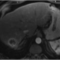
Treatment algorithms of HCC and metastases rely on cross-sectional imaging (CT or magnetic resonance imaging [MRI]) to identify and characterize potential lesions. The ability of interventionalists to treat lesions of concern is predicated on lesion visibility intraprocedurally. With only digital subtraction angiography (DSA) imaging, interventionalists must heavily rely on the arterial phase of image acquisition to both identify the lesions of concern and determine the best approach to treatment with regard to the degree of vessel subselection and appropriate catheter/wire selection. CBCT affords the operator the ability to acquire cross-sectional images such that direct comparison to preprocedure imaging is possible (▶ Fig. 1.2).

As shown by Miyayama and colleagues, sensitivity for detection of small HCCs during chemoembolization is equivalent to contrast-enhanced MRI when dual-phase (hepatic arterial and arterioportal phases) CBCT is employed. 5 In their series of 68 tumors, nonselective DSA also failed to detect 19 tumors seen on preprocedure CT or MRI. Eight of the 68 tumors treated were also not seen on preprocedure imaging, apparent only on intra-procedural CBCT. The added value of dual-phase imaging appears to be an important future direction (▶ Fig. 1.3). In an earlier study of 82 tumors, Loffroy and colleagues showed the utility of dual-phase CBCT. Sensitivities of arterial and venous phases alone for detection of HCC were 71.9 and 86.6%, respectively. Overall sensitivity when both arterial and venous phases were evaluated improved to 93.9%. Notably, of 23 tumors that were not identified on arterial phase, 17 were detected on venous phase. 6 See ▶ Table 1.1 for a standard CBCT dual-phase imaging protocol.

A second challenge frequently encountered by interventionalists during hepatic arterial interventions is difficulty in confidently defining the arterial anatomy in regard to both the tumor-feeding branches and nearby nontarget extrahepatic arteries. Recognition of variant arterial anatomy supplying the small bowel, stomach, diaphragm, and skin is requisite for safely performing hepatic arterial chemoembolization and radioembolization. Failure to recognize these variants can result in nontarget embolization to these structures. 7 CBCT is a useful tool to identify vessels not initially apparent on DSA. CBCT also allows the operator to clearly identify the origins and supplies of indeterminate vascular structures, obviating the need for multiple vessel subselections and DSAs from various projections to confirm that intervention may be performed without risk of nontarget embolization. 4
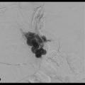
In addition to identifying potential nontarget vessels, CBCT has also been shown to be useful in assisting the operator in identifying the tumor-feeding branch(es) (▶ Fig. 1.4). Currently, there are two systems that can detect the tumor-feeding branch(es) and guide microcatheter positioning (Flight Plan for Liver, GE Healthcare, Chalfont St Gilles, England or EmboGuide, Philips Healthcare, Best, the Netherlands). After acquisition of a CBCT volume, 3D segmentation of the lesion of interest is performed. The system then analyzes the lesion of interest and identifies and annotates potential feeding vessels. The potential vessels are then projected as an overlay and the roadmap is registered to the live view. The roadmap will make adjustments according to C-arm angulation, table translation, and magnification changes. The clinical utility of this system has been verified. In a study of 68 tumors, 81 of 100 tumor-feeding branches could be identified using the detection software in conjunction with CBCT. When nonselective DSA was used alone, only 38 of the 100 branches could be identified. There were also 27 false-positive branches when only nonselective DSA was used. 5

Related posts:
 6 Management of Complications of Portal Hypertension: Balloon-Occluded Retrograde Transvenous Obliteration, Plug-Assisted Retrograde Transvenous Obliteration, Coil-Assisted Retrograde Transvenous Obliteration, and Balloon-Assisted Antegrade Transvenous Obliteration
 15 Hepatocellular Carcinoma: Staging and Clinical Management
 12 Malignant Obstructive Jaundice
 23 Yttrium-90 Radioembolization of Malignant Liver Tumors
 27 Image-Guided Colorectal Obstruction Management
 28 Obesity and Bariatric Embolization
Stay updated, free articles. Join our Telegram channel

Full access? Get Clinical Tree


