12 General Anatomy of the Heart
Introduction
This chapter provides a general description of the heart anatomy and offers an outline of the relevant clinical information. Most images are produced using state of the art multidetector computed tomography (MDCT) scanner on living subjects or by meticulous dissection techniques on cadaveric specimens. Anatomical detail of specific heart structures will be presented in the subsequent chapters dedicated to that structure. Imaging study of the heart can be obtained with plain radiographs, computed tomography (CT) scan, magnetic resonance imaging (MRI), echocardiography, and nuclear imaging. Each modality has its own shortcomings or advantages. Plain radiographs are cheap and an easy way of evaluating the heart size and cardiac borders. Anatomical details require further imaging studies. CT with contrast can evaluate details of the heart morphology and the relationship of the heart with the lungs and vessels. MRI has a better contrast resolution and tissue characterization power than CT. Echocardiography has the highest temporal resolution and fast-moving structures such as cardiac valves are best assessed with echocardiography.
Heart Borders in the Thorax
Knowing the radiological borders of the heart in different projections is important for imaging interpretation of heart in normal or pathological states. Plain radiographs are the first step in the imaging evaluation of the heart, lung, and major thoracic vessels.
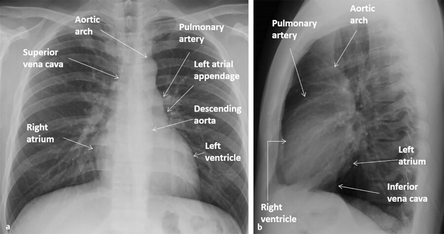
With plain films, the heart margins can be assessed. Only the margins that are border forming with the lungs or air-containing structures (main stem bronchi, esophagus) can be seen (Fig. 12‑1). That is why it would be impossible to see the borders of the cardiac chambers facing the diaphragm or the mediastinum using plain films unless surrounded by air. Showing these borders requires imaging with CT or MRI.
In general, chest X-rays are obtained in frontal and lateral positions. Most X-rays especially in outpatient setting are obtained in posteroanterior (PA) direction while the patient is in upright position while the X-ray cassette placed in front of patients. Chest radiographs especially in bedridden patients are obtained in anteroposterior (AP) direction with the film placed behind the patient and the X-ray tube is positioned anteriorly. On AP films the heart is generally magnified and appears larger. Magnification is also higher in a portable X-ray compared with an upright film. Chest films are generally obtained at deep inspiration. The heart appears larger and more horizontal in expiratory films due to elevation of the diaphragm. Positional and respiratory variations in heart size also are seen in CT scan images but to a lesser degree.
In order to recognize the cardiomediastinal pathologies in plain films, it would be essential to be familiar with radiographic borders of the heart in different projections (Fig. 12‑1 a). On frontal projections (AP or PA views), the right cardiac border is formed by the right atrium (RA) while the left cardiac border is formed by the left ventricle (LV) (Fig. 12‑2 a). The right ventricle (RV) and the left atrium (LA) are not border forming with lungs in PA views and additional projections are required to demonstrate them. The diaphragmatic surface of the heart is formed by the RV. On the lateral projection, the anterior cardiac border is the RV while the posterior cardiac border is composed of both the LV and the LA (Fig. 12‑2 b).

Anatomical Position of the Cardiac Structures
Detail evaluation of the cardiac anatomy and localizing specific structures within the heart require cross-sectional imaging. From these cross-sectional views three-dimensional (3D) (volume-rendered) projections of the heart can be reconstructed. Using CT, MR, or echocardiography cross-sectional images can be obtained or reconstructed in any directions (Fig. 12‑3 , Fig. 12‑4 , Fig. 12‑5 , Fig. 12‑6). However, radiologists and cardiologists use certain standard planes in order to define a specific anatomy or pathology of interest. The terminologies used for these views are in reference to the body (chest) and the heart.
Standard planes in reference to the chest (body planes) include three orthogonal cuts in axial (transverse), coronal, and sagittal orientations (Fig. 12‑7). Additional body projections commonly used in CT and catheter angiography studies of the heart and coronary arteries include right anterior and left anterior oblique projections in various angles with different caudal or cranial angulations (Fig. 12‑8). Heart planes including short axis, horizontal long axis, and vertical long axis also involve three orthogonal planes but in reference to the heart itself 1 , 2 (Fig. 12‑9). Short-axis images, which correspond to a plane parallel to the atrioventricular (AV) groove, are transverse cuts of the heart. Horizontal long-axis (four-chamber) views are double oblique planes of the heart perpendicular to both the interventricular septum and AV planes. Vertical long-axis (two-chamber) views of the heart are parallel to the interventricular septum plane and perpendicular to the AV plane (Fig. 12‑9). Taking above concepts into consideration, the location of many of the anatomical structures or a specific pathology of the heart can be addressed using either the heart or the body as the reference. This has caused confusion and discrepancy in the anatomy or radiology nomenclature to localize some anatomical sites. For example, the two papillary muscles of the LV are located superiorly and inferiorly in reference to the body (chest) but positioned anteriorly and posteriorly in reference to the heart (Fig. 12‑10).


Anatomical Surfaces and Angles of the Heart
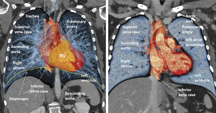
The heart is located in the middle mediastinum. It is surrounded by the epicardial fat and the pericardial sac. The epicardial fat is continuous with the mediastinal fat along the major vessels at the superior aspect of the heart. Superiorly, the heart is connected to the aorta, pulmonary artery, and superior vena cava (SVC). Inferiorly, it is connected to the inferior vena cava (IVC) (Fig. 12‑3).
The sternum and costal cartilages are located anterior to the heart and provides rigid protection to the heart during blunt trauma. The heart has an extensive diaphragmatic surface inferiorly (Fig. 12‑3). Posteriorly, the heart lies on the esophagus and tracheal bifurcation, and main stem bronchi of the lungs.
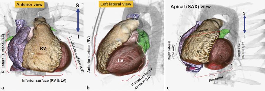
The true posterior surface of the heart is commonly referred as the base of the heart which is formed largely by the LA. The term “base of the heart” is not frequently used and should be restricted to the “origin of the great vessels.” The inferior surface of the heart is closely related to the diaphragm and may be called diaphragmatic (Fig. 12‑3 , Fig. 12‑6). In supine position, along with elevation of the diaphragm, the heart lies horizontally and its lower surface largely faces the diaphragm (Fig. 12‑3). However, in upright position, with full inspiration, the heart stands vertically and less walls face inferiorly. 1 Because of differences in morphology of the RV and LV, the diaphragmatic surface of the RV is truly facing inferiorly but the diaphragmatic wall of the LV faces posteroinferiorly (Fig. 12‑6 , Fig. 12‑11).
The ventricular part of the heart looks like a three-sided pyramid. When viewed from its apex, the three sides of the ventricular mass are readily seen (Fig. 12‑12). Two prominent edges are distinguished. The acute margin lies inferiorly and parallel to the diaphragm. It corresponds to a sharp angle between the sternocostal and diaphragmatic surfaces of the RV. The obtuse margin runs posteriorly and superiorly along the lateral (posterior) margin of the LV. It is more or less diffuse in its transition compared with the acute margin.

Right Atrium
The RA is an important chamber with a complicated morphology. It is the chamber of the heart that receives systemic venous blood return from the SVC and IVC and coronary venous return from the coronary sinus. 2 The RA is home to important parts of the cardiac conduction system including, the sinoatrial (SA) node, the AV node, and internodal bundles.
The RA forms the right lower cardiomediastinal border on plain radiographs (Fig. 12‑12). Looking at 3D images of the heart from the superior aspect of the chest, the RA is facing anteriorly on the right side of midsagittal plane of the chest, whereas the LA is situated posteriorly and more or less in midline (Fig. 12‑13).
The RA has the shape of a rotated box. The longest diameter of the RA box is in superior inferior direction. The SVC connects to the posterior margin of the superior wall of the RA near the interatrial septum. The IVC connects to the posterior margin of the inferior wall of the RA (Fig. 12‑14). The superior and inferior connections of the cava are best seen on the lateral CT images of the chest (Fig. 12‑13). On axial images, the RA box is rotated along the Z-axis of the body. Therefore, the lateral wall is facing laterally and posteriorly whereas the medial wall facing medially and anteriorly. As a result, the anterolateral corner of the RA, formed by the junction of the anterior and lateral walls, is the major border-forming structure on frontal plain X-rays (Fig. 12‑13 , Fig. 12‑14). This corner is specifically formed by the right atrial appendage. The tricuspid valve forms the inferior to midpart of the medial wall of the RA and faces medioanteriorly toward the RV (Fig. 12‑13 , Fig. 12‑15). The plane of the tricuspid is mildly on the right of midsagittal plane. The superior part of the medial RA wall is located next to the aortic root and the inferior part of the medial wall connects to the coronary sinus and forms the right atrial wall of the inferior pyramidal space. The interatrial septum forms part of the posterior wall of the RA (Fig. 12‑16 , Fig. 12‑17). In general, the anterior and lateral walls are the free walls of the RA. Most surgical approaches to access the intracardiac structures are performed through the anterior and lateral walls.
The RA comprises of three components: the appendage, the venous part (sinus venarum), and the vestibule. 2 The atrial appendage is derived from the primary atrium. The right atrial appendage is the largest component forming the anterolateral aspect of the RA extending between the superior and inferior walls (Fig. 12‑15). Its inner surface appears trabeculated formed by multiple pectinate muscles. The venous part of RA is derived from the sinus venosus and is located posterolaterally and connects to the SVC, the IVC, and the coronary sinus (Fig. 12‑14 , Fig. 12‑15). From the third week after the development of the primitive heart tube, the primary atria are separated from the sinus venosus by a segmentation termed the sinoatrial ring. The sinus venosus has two horns. The right horn gives rise to all the intercaval regions of the RA (sinus venarum) including the crista terminalis, the Eustachian ridge, and the Thebesian valve (Fig. 12‑6). The left horn gives rise to the coronary sinus.
The atrial vestibule of the RA is derived from the embryonic AV canal. It is a smooth muscular rim surrounding the tricuspid orifice 1 (Fig. 12‑18). The pectinate muscles do not reach this area (Fig. 12‑19). The right coronary artery (RCA) runs in the epicardial fat next to the vestibule.
One of the important morphological structures of the RA is the crista terminalis. This C-shaped muscular ridge separates the smooth-walled venous part from the trabeculated appendage. 3 The crista terminalis extends between the superior and inferior walls (Fig. 12‑19). It starts anterior to the orifice of the SVC, passes rightward and inferiorly toward the RA vestibule. In front of IVC, the crista terminalis continues as an array of finer bundles that blends in an area of the inferior atrial wall known as the cavotricuspid isthmus. Terminal groove is a fat-filled sulcus on epicardial side of the RA which corresponds internally to crista terminalis (Fig. 12‑15). The sinus node and terminal segment of SA node artery are located in this groove, close to the superior cavoatrial junction (see the sinoatrial node).


Superior Right Atrium Landmarks
The most important landmark of the roof of the RA is the superior cavoatrial junction and the structures around it (Fig. 12‑14). In this region, the crista terminalis originates anterior to the orifice of the SVC (Fig. 12‑19 , Fig. 12‑20). Laterally, the crista terminalis continues its normal anatomical course in the lateral RA wall. Medially, the crista terminalis blends with the interatrial muscular bundle commonly known as Bachmann’s bundle (Fig. 12‑19).
In some CT images of the heart a large pectinate muscle trabeculation band is seen arising from the precaval portion of the crista terminalis. This parasagittal band is a remnant of the septum spurium and should not be mistaken with intra-atrial thrombus (Fig. 12‑20).
Another important landmark in the superior portion of the RA is the SA node. The SA node is a banana-shaped structure in the subepicardial side of superior cavoatrial junction within the crista terminalis 4 (Fig. 12‑21). The mean length of the SA node is reported 20 ± 3 mm 4 and its cross-sectional diameter is usually less than 5 mm. 5 It is the source of the cardiac impulse and composed of specialized cells slightly smaller than normal working cells. With age, the amount of connective and fatty tissue increases with respect to the area occupied by the nodal cells and the node becomes atrophic. 5 , 6 The SA node can be localized in axial CT images by locating the SA node artery passing along the crista terminalis (Fig. 12‑22). The SA node gradually penetrates musculature of the crest to rest in the subendocardium. Because of the vicinity of the SA node to the epicardial surface, it may be damaged in selected cardiac surgeries or extensive pericardial diseases. 7 Modification of the sinus node activity using radiofrequency ablation (RFA) has been established as a treatment for inappropriate sinus tachycardia. 8
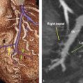
The SA node artery is usually, a single branch, arising from the proximal RCA (60%) or left circumflex (LCx) artery (40%) 7 , 9 (Fig. 12‑23). In an anatomical study of the conduction system arteries by CT scan, single SA node artery from the RCA was seen in 66% and from the LCx artery in 28% of studies. 10 A dual blood supply to SA node was seen in 6%: one from the RCA and the other from the LCx artery. Regardless of its artery of origin, the SA node artery usually courses along the superior interatrial groove toward the superior cavoatrial junction (Fig. 12‑23). At the cavoatrial junction, SA node artery course becomes variable and may circle either anteriorly (precaval) or posteriorly (retrocaval) to enter the node 10 (Fig. 12‑24).


Anterolateral Right Atrium Landmarks
The body of the crista terminalis is an important structure in the lateral RA wall that could be the source of several forms of atrial tachyarrhythmias. 11 The crista terminalis varies in size and extent in different individuals and should not be mistaken with intra-atrial pathology (Fig. 12‑25). Excess epicardial fat can infiltrate around the RA causing marked thickening of the crista terminalis which may mimic a mass (Fig. 12‑25, lower row). It may be associated with lipomatous hypertrophy of the interatrial septum. 12 Both conditions are due to excessive accumulation of fat in the epicardial space. 13
Medially and superiorly, the crista terminalis connects to the interatrial Bachmann bundle (Fig. 12‑19). On the right, this broad band of circumferential interatrial myofibers can be traced to the junction of the RA and SVC (Fig. 12‑27). On the left, the bundle blends on the epicardial musculature of the LA toward the neck of the left atrial appendage (LAA) (Fig. 12‑27). 14 , 15 This interatrial band ensures rapid interatrial conduction, leading to physiological biatrial contraction. Changes in the musculature of Bachmann’s bundle could block or prolong interatrial conduction resulting in abnormal atrial excitability, atrial dysfunction, atrial fibrillation (AF), and other arrhythmias. 16 The principal vascular supply of Bachmann’s bundle is believed to stem from the SA node artery and its branches 17 (Fig. 12‑26). Anatomical variants of this region are common (Fig. 12‑27). An anatomical study of Bachmann’s bundle and its vascular supply by CT in normal and abnormal patients showed that Bachmann’s bundle was less visible in the patients with severe coronary artery disease as it was replaced with fat 17 (Fig. 12‑27).


Inferior Right Atrium Landmarks
The inferior part of the RA is an interesting area with several important anatomical landmarks. The IVC and the coronary sinus connect to this portion of the RA. The Eustachian valve is seen at the anterior margin of the IVC (Fig. 12‑28). It is a remnant of the embryonic right valve of the sinus venosus. Embryologically, the Eustachian valve directs oxygenated blood from the IVC across the patent foramen ovale (PFO) into the systemic circulation. 18 It is usually membranous and variably developed. It may look fenestrated or contain muscles. Usually, it inserts medially to the Eustachian ridge at the medial atrial wall. In some cases, the Eustachian valve is large, causing difficulty to pass a catheter (Fig. 12‑29). Patients with large Eustachian valve have a higher incidence of PFO. 16
The inferior wall of the RA between the IVC and the tricuspid valve is a quadrilateral region known as “cavotricuspid isthmus.” 19 This part of the right atrial vestibule is the target of catheter ablation techniques for isthmus-dependent atrial flutter. 20 There are variable sizes and morphology that changes with cardiac cycle with the largest diameters during midventricular systole. 21 Obstacles such as large Eustachian ridge/valve, aneurysmal pouches, or even a concave deformation of the entire isthmus may lead to more difficult ablation sessions. Therefore, knowledge of anatomical variants of this region is very important 21 (Fig. 12‑30 , Fig. 12‑31 , Fig. 12‑32).
It is common to observe outpouchings in the medial and lateral margins of the inferior wall of the RA. The medial outpouching inferior to the orifice of the coronary sinus is known as the sub-Eustachian sinus of Keith. It is an extension of a pouch-like isthmus under the orifice of the coronary sinus. Since it is sub-Thebesian rather than sub-Eustachian, some prefer to call it sub-Thebesian sinus/recess 2 (Fig. 12‑32 , Fig. 12‑33). This anatomical variant is recognized as one of the major procedural difficulties in catheter interventions of the RA and could also be the substrate for reentrant circuit during atrial flutter.
The coronary sinus also connects the inferomedial aspect of the RA. The coronary sinus drains most epicardial coronary venous flow into the RA. Its orifice is guarded by the Thebesian valve. The valve is usually a thin semilunar fold in anteroinferior rim of the ostium and can be seen in most CT angiography studies of the heart 22 (Fig. 12‑34). The Thebesian valve is continuous with the Eustachian valve.
The Chiari network represents coarse or fine fibers in the RA, arising from the Eustachian or Thebesian valve, and strands within the RA connecting these valves with the crista terminalis, right atrial wall, or interatrial septum (Fig. 12‑35). It is a remnant of the embryonic right valve of the sinus venosus, 23 , 24 and should be differentiated from a large Eustachian valve. The Chiari network fibers may be seen in high-quality CT or MR studies (Fig. 12‑35). It could be a risk factor for clot formation. 18


Medial Right Atrium Landmarks
The inferior part of the medial RA wall above the orifice of the coronary sinus is called the triangle of Koch. It is of significant importance to electrophysiologists because the AV node resides in this triangle and it is the site for catheter ablation procedures which are guided largely by anatomical landmarks (Fig. 12‑36 , Fig. 12‑37). The AV node consists of a compact portion near the apex and an area of transitional cells near the base of the triangle (Fig. 12‑37). The central fibrous body resides in the apex of the triangle and the ostium of the coronary sinus holds its base. When viewed from the RA, the triangle is delimited by the hinge line of the septal tricuspid leaflet on the ventricular side and the Eustachian ridge (tendon of Todaro) on the atrial side. 25 The triangle of Koch is the target of ablation for AV node reentrant tachycardia (AVNRT), septal and paraseptal accessory pathways, and atypical forms of atrial flutter. 26 , 27 The size of the triangle varies in different individuals with a mean height of 26 ± 8 mm. 28 , 29 Patients with large triangles require additional ablations of the septal region which may increase the rate of complication. 28
The vestibular atrial wall between the coronary sinus ostial rim and the hinge line of the septal leaflet of the tricuspid valve is known to electrophysiologists as the septal isthmus (Fig. 12‑36). It is one of the targets of ablation of the ”slow pathway” AVNRT. The AV node artery can run very close to the septal isthmus (3.5 ± 1.5 mm) being at risk of coagulation during ablation 28 , 30 (Fig. 12‑14 b). In general, ablations for slow pathway are performed near the base of triangle where the transitional part of the AV node is located to avoid injury of the compact AV node (fast pathway) or the AV node artery. 29
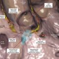
The tendon of Todaro runs deep in the atrial musculature (the sinus septum) between the coronary sinus and the fossa ovalis. It extends from the commissure between the Eustachian and Thebesian valves to the central fibrous body 31 (Fig. 12‑36). The tendon of Todaro is not visible in the internal view of the RA. Visible representative of it on the internal atrial surface is the Eustachian ridge which can be prominent enough to be visible in CT angiographies in 25% of individual 21 (Fig. 12‑31 , Fig. 12‑36). The significance of demonstration of a large Eustachian ridge is more related to the need for its catheter ablation to achieve a complete paraseptal isthmus block in patients with atrial flutter. 32 The AVN artery originates from the distal RCA and penetrates into the base of the posterior interatrial septum (inferior pyramidal space) at the level of crux of the heart in 80 to 90% of patients (Fig. 12‑38). In the remaining, it originates from the distal LCx artery. 10 , 33 , 34 , 35


Left Atrium
Over the last decade, there has been tremendous attention by the anatomists and electrophysiologists to the anatomy of the LA. The LA has become the main target of catheter ablation in patients with chronic AF.
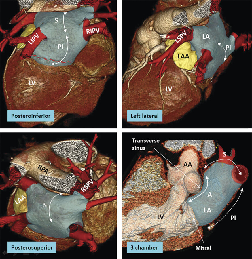
The LA is the posterior chamber of the heart that receives pulmonary venous drainage from the four pulmonary veins. 1 The shape of the LA may be compared to box sitting in front of the descending thoracic aorta and the esophagus. The LA is divided into five poorly demarcated walls: anterior (anterosuperior), posterior (posteroinferior), superior, left lateral, and septal (anteroinferior). The relations of the LA to adjacent structures are important (Fig. 12‑16 , Fig. 12‑39).
The main pulmonary artery and the right pulmonary artery are close to the superior wall of the LA and separated from the LA by the transverse sinus (Fig. 12‑13 , Fig. 12‑19). The pulmonary veins connect to the posterosuperior aspect of the LA on each side. The ascending aorta is located between the anterior wall of the LA and the medial wall of the RA (Fig. 12‑14). They are separated inferiorly by the extracardiac adipose tissue and superiorly by the transverse sinus of the pericardium (Fig. 12‑39). The left SA node artery travels in the epicardial fat of the transverse sinus at the junction of the superior and anterior walls of the LA (Fig. 12‑23). The noncoronary sinus of the aorta faces the interatrial septum. The posterior wall of the LA is close to the esophagus and the descending aorta. The orifice of the LAA is located anterolaterally at the left superior corner of the LA anterior to the left superior pulmonary vein orifice.
The interatrial Bachmann bundle marks the junction of the anterior and superior walls of the LA.
The interatrial septum forms the septal (anteroinferior) wall of the LA facing anteriorly and slightly on the right of midsagittal plane (Fig. 12‑17). The mitral valve is the opening of the LA to the LV. It is located anterolaterally at the inferior half of the LA and on the left of midsagittal plane (Fig. 12‑17 , Fig. 12‑39). The left main stem bronchus passes above the left superior corner of the LV. With LA enlargement, the left bronchus will be pushed superiorly. This causes widening of the tracheal bifurcation angle, a useful sign of LA enlargement on plain films (Fig. 12‑40).

The anterior wall thickness measures 3.3 ± 1.2 mm. 36 Part of the anterior wall immediately inferior to the Bachmann bundle and posterior to the aorta can be very thin (1–2 mm). It may contain small outpouchings. These features make the anterior wall of the LA susceptible to perforation during catheter interventions. The LA wall is also very thin at the right or left venoatrial junctions. 37 , 38 , 39 The superior wall, or dome, is the thickest, measuring 3.5 to 6.5 mm. 2 With the exception of the interatrial muscle bundles (Bachmann’s bundle), the muscles of each atrium are confined to its wall. The highest portion of the LA is at the ostium of the left superior pulmonary vein (Fig. 12‑13). The left pulmonary veins are usually higher than the right pulmonary veins (Fig. 12‑13).
Components of the Left Atrium
As with the RA, the LA consists of a venous component, an appendage and a supravalvular vestibule (Fig. 12‑41). Most part of the LA except the appendage is smooth-walled. The superior and posterior walls of the LA form the pulmonary venous component, with the venous orifices at each corner 36 (Fig. 12‑39). In early embryonic stage, the pulmonary venous component is a small single vein that opens into the posterior LA adjacent to the developing left AV junction. Subsequent to atrial septation the venous component expands and gradually shifts superiorly to form the roof of the LA with four venous orifices on the sides.
The vestibular component surrounds the mitral orifice (Fig. 12‑16 , Fig. 12‑41). As with the developing RA, part of the initial AV canal also forms the vestibule of the mitral valve. 40 Large branches of the LCx artery extend to the posterior aspect of the LA vestibule usually 10 mm above the ostium of the LV. In a dominant LCx artery distal branches can reach to the external crux of the heart. However, exceptions occur and large RCA branches may run in contact with the vestibule. An anatomical area of the vestibule located between the orifice of the left inferior pulmonary vein and the mitral annulus is known as left atrial or mitral isthmus 41 (Fig. 12‑42). There is marked variability in the dimensions and wall thickness of the mitral isthmus. This area may be the source of recurrence after circumferential pulmonary vein catheter ablation for AF. 42


Pulmonary Vein Ostia
Normal pulmonary vein anatomy consists of two right-sided and two left-sided pulmonary veins with separate ostia (Fig. 12‑39). This arrangement is commonly variable. The pulmonary vein ostia are ellipsoid with a longer superior–inferior dimension. The right superior pulmonary vein is located close to the SVC, and the right inferior pulmonary vein projects horizontally (Fig. 12‑14). The left superior pulmonary vein is close to the LAA and the left inferior pulmonary vein courses near the descending aorta. The veins are larger in men. In patients with enlarged LA or persistent AF veins can be larger. The superior pulmonary vein ostia are larger (19–20 mm) than the inferior ostia (16–17 mm). 43 The ostium of the pulmonary veins is a common location for radiofrequency catheter ablation to treat AF. The ostial diameters influence the selection of the ablation catheter size used. The pulmonary vein trunk is defined as the distance from the ostium to the first-order branch.
Common anomalies include a conjoined (common) left or right pulmonary vein in 25% of individuals. 43 A conjoined pulmonary vein is seen more frequently on the left than the right side. 44 Supernumerary veins are also frequent. The most common is a separate right middle PV, which drains the middle lobe of the lung 45 (Fig. 12‑43). One or two middle lobe vein ostia can be seen in 26% of patients. 44 The ostial diameter of the right middle PV is smaller than that of the other veins (mean, 9.9 ± 1.9 mm). The ectopic focus originating from the right middle PV could initiate AF, which is cured by catheter ablation of the right middle PV. In some patients, there is a supernumerary PV that shows an aberrant insertion, with a perpendicular position in relation to the LA posterior wall. The supernumerary branch usually drains the superior or posterior segment of the right upper lobe and characteristically passes behind the bronchus intermedius. In the absence of one pulmonary vein, careful examination of the intrathoracic venous system is required to exclude presence of a partial anomalous pulmonary venous return (Fig. 12‑44).
The presence of atrial myocardial tissue extending over the first centimeter of ostial wall of the pulmonary veins has been confirmed both histological examinations. 46 The myocardial sleeve is thickest at the venoatrial junction especially in the left superior pulmonary vein. Although, different mechanisms of AF exist, these myocardial sleeves are believed to be the major source for the development of reentry that triggers AF. 47 In the past, the most common ablation strategy was electrical isolation of the pulmonary veins by creating circumferential ablation lines around the individual or bilateral pulmonary vein ostia. The lines are either guided by fluoroscopy, 3D electroanatomical mapping, or intracardiac echocardiography. 48 , 49 The focus of radiofrequency or cryoablation strategies shifted from the pulmonary vein to the atrial tissue located in the antrum due to the fact that many nonpulmonary vein trigger points for AF are located in the antrum rather than the pulmonary veins and that radiofrequency delivery may cause pulmonary vein stenosis. 50 In antrum ablation, the most common sites are the LA “roof” connecting the superior aspects of the left and right upper pulmonary vein isolation lesions and the region of tissue between the mitral valve and the left inferior pulmonary vein (the mitral isthmus). 51
Incidental discovery of small membranes within the LA near the orifices of the pulmonary veins and adjacent to the superior part of the atrial septum is not rare (Fig. 12‑45). Large membranes should raise the possibility of cor triatriatum sinister. This congenital anomaly is rare but surgically correctable. 52


Left Atrial Appendage
The LAA is derived from the primitive atrium and has a rough trabeculated surface. The LAA interior surface is lined by complicated network of fine pectinate muscles. The LAA is a potential site for deposition of thrombus owing to its narrow neck with the LA. 53 It also appears to be responsible for triggering AF in some patients presenting for repeat procedures of catheter ablation. 54
There is a wide variation in the configuration of the LAA (Fig. 12‑46). The LAA is characteristically a small finger-like extension of the LA with a multilobulated appearance in 80% of hearts 53 (Fig. 12‑46). The tip of the LAA can be in a variety of positions, lying over the left anterior descending (LAD) coronary artery, pointing posteriorly, or even directed medially toward the back of the aorta. Using imaging, the LAA morphologies are classified into cactus (30%), chicken wing (48%), windsock (19%), and cauliflower (3%). 54 The rate of thrombus formation is less in nondilated LAA with simple morphology compared with dilated LAAs with complicated shapes. The orifice of the LAA is at the junction of the anterior and the lateral wall, anterior to the left superior pulmonary vein. The axis is directed posteriorly, inferiorly, or anteriorly. It may rotate internally into the transverse sinus (Fig. 12‑46 c). Rarely, the tip of the LAA may reopen into the anterior wall of the LA (double orifice). The proximal portion of the LCx artery runs in contact with the inferior wall of the LAA. A variable relationship of the coronary arteries to the LAA exists.
The left lateral “ridge” between the LAA and the left pulmonary veins was first described by Keith in 1907 as the “left tenia terminalis.” The thickness of the ridge is less than 5 mm in 75% of the hearts (Fig. 12‑47, Fig. 12‑48). Thickened ridge can be mistaken for a thrombus or atrial mass. Within the fold runs the remnant of the vein of Marshall, multiple autonomic nerve bundles, and a small atrial artery which, in some cases, is the left SA node artery (S-shaped SA node artery) 55 , 56 (Fig. 12‑47). Persistent left SVC also passes in this region. The S-shaped SA node artery is an anatomical variant of the SA node artery in 14% of coronary CT angiographies. It originates from the posterolateral part of the LCx artery 57 (Fig. 12‑47). Surgical or catheter ablation interventions of the LA may pose this artery at risk of injury.
Accessory LAA or LA diverticula are common anatomical variants in 30% of the hearts 58 , 59 These outpouchings are seen in two anatomical locations: the anterior wall of the LA (projects into the transverse sinus) and the left atrial isthmus (Fig. 12‑49). Description of this anatomical variant in radiology reports is required as they may interfere with ablation procedures or be a potential cause of thrombus formation.


Important Periatrial Structures
Important periatrial structures include the esophagus, vagus nerves, phrenic nerves, and descending thoracic aorta. Posterior to the posterior left atrial wall is a layer of fibrous pericardium and fibrofatty tissue of irregular thickness that contains esophageal arteries and the vagus nerve plexus (Fig. 12‑50). These anatomical structures may be affected by RFA. The esophagus follows a variable course along the posterior aspect of the LA and it is a movable structure. 60 In 40% of cases, it passes along the middle portion of the posterior LA wall 37 , 60 (Fig. 12‑51). Damage to the esophageal wall may rarely result in the formation of an atrial esophageal fistula.
The vagus nerves pass behind the root of the lungs and form right and left posterior pulmonary plexuses (Fig. 12‑50). Branches of the pulmonary plexuses form the posterior and anterior esophageal plexuses which enter the abdomen through the esophageal diaphragmatic opening to become the posterior and anterior vagal trunks that innervate the stomach and pyloric canal and the digestive tract as far as the proximal part of the colon. 61 Thermal injury may involve the periesophageal vagal nerves resulting in a syndrome of acute delayed gastric emptying. 62
The phrenic nerves lie along the lateral mediastinum and run from the thoracic inlet to the diaphragm (Fig. 12‑52). Phrenic nerve injury results from direct thermal injury, usually to the right phrenic nerve, which is located lateral to the SVC and anterior to the right superior pulmonary vein. 63 , 64 Less frequently, ablation within the LAA can result in the left phrenic nerve damage which may pass close to the apex of the LAA in 30% of the hearts. 63 On the other hand, the left phrenic nerve passes close to the LV. CT coronary angiography can demonstrate the left phrenic neurovascular bundle as it passes over the LV pericardium in two-thirds of the studies 65 (Fig. 12‑52).


Interatrial Septum
The true atrial septum is limited to the floor of the membranous fossa ovalis and its immediate muscular rim at the anteroinferior margin, which is confluent with the apical part of Koch’s triangle. The floor of the fossa ovalis represents the embryonic primary atrial septum (septum primum) which fuses to the remainder of the septal wall within the first 2 years of life. Fusion is incomplete in about 25% of people, leaving a PFO 66 (Fig. 12‑53). The muscular rim (also known as the limbus) of the superior, inferior, and posterior margins of the fossa ovalis is formed by the infolding of the right and left atrial walls. The epicardial fat fills the interatrial groove between the infolding walls. To understand the above concepts, a review of the embryology of the septum is necessary.
Atrial septation is a complex process involving several tissue components. 67 Atrial septation starts with the appearance of a ridge in the atrial roof called primary atrial septum (septum primum). The primary septum grows toward the cushions of the AV canal. The leading edge of the primary septum (mesenchymal cap) connects to another structure known as “vestibular spine” (Fig. 12‑54). The vestibular spine is a mesenchymal protrusion from the mediastinum into the common atrium that closes the gap of the primary atrial foramen (ostium primum) between the primary septum and the inferior endocardial cushions of the AV canal. Later muscularization of the vestibular spine and the mesenchymal cap occur, producing the secondary component of the real atrial septum. Along with above developments, the attachment of the primary septum to the atrial roof begins to break down to form the secondary atrial foramen (foramen ovale/ostium secundum). 68 The remainder of the primary atrial septum becomes the flap valve of the foramen which is attached to the vestibular spine anteriorly (Fig. 12‑54). With further development, infolding of the posterosuperior wall of RA close to pulmonary venous sinus of the LA occurs to form a wall previously known as septum secundum. As the name implies, this infolding only represents invagination of the atrial wall with epicardial fat sandwiched between the infolded walls (Fig. 12‑55). Therefore, the superior, posterior, and inferior muscular rims of the fossa ovalis are formed by infolded atrial wall (Fig. 12‑56). These rims are not real septum and more correctly defined as the “interatrial groove” and the rim attached to the membranous fossa ovalis commonly named as the “limbus” (Fig. 12‑55). Only the anterior/anteroinferior rim formed by the vestibular spine is a real muscularized septum buttressing the atrial septum to the AV junctions (ventral atrial buttress) (Fig. 12‑54). Therefore, inadvertent needle or catheter puncture outside the limited margins of the limbus during transseptal interventions results in perforation into the pericardial sinuses. At particular risk is the puncture of the anterior rim of the interatrial groove, which is in close aortic valve (Fig. 12‑56). Excess accumulation of the epicardial fat in the interatrial grooves results in thickening of the atrial wall which may reach up to 2 cm in thickness. Thickness of more than 2 cm is defined as lipomatous hypertrophy (Fig. 12‑56).


Defect in the primary atrial septum is called “ostium secundum” defect. Defect in the vestibular spine is called vestibular defect. 69 Abnormal growth of the vestibular spine and mesenchymal cap can lead to ostium primum atrial septal defect (ASD). Ostium primum ASD is now categorized in AV canal defects because of associated AV cushions defects.
Patent Foramen Ovale
Closure of the septum primum is complete when the valve becomes adherent to the rim to form the fossa ovalis. The size of fossa ovalis and its margins may vary greatly. In 25 to 35% in autopsy studies, 66 , 70 the seal is incomplete leaving a crevice at the anterosuperior quadrant of the rim that allows a probe to be passed obliquely from the RA into the LA (PFO) (Fig. 12‑57). This nonfusion creates the tunnel-like PFO orientated in a craniocaudal, PA, and right-to-left axis. 71 The incidence and size of PFO do not differ with gender but varies significantly with age; 34% of PFOs occurs in the first three decades, 25% in the 4th to 8th decades, and 20% in the 9th and 10th decades. 66 The size of PFO increases progressively from a mean of 3.4 mm in the first decade to 5.8 mm in the tenth decade (possibly because smaller defects seal with age).
Normally, the PFO is closed by the higher left atrial-to-right atrial pressure gradient. If the left atrial pressures rise (i.e., pulmonary hypertension), a small clot may pass directly from the RA into the left side and resides in different organs such as brain to cause a stroke. This condition is called paradoxical embolism. The presence of shunting through the PFO not only depends on the transatrial pressure gradient, but also likely relates to anatomical features of the PFO. These include the size of opening into the RA, length of the PFO tunnel, and the extent of excursion of the flap membrane. Moreover, the risk of stroke appears to increase in the presence of structures that direct flow toward a PFO (i.e., prominent Eustachian valve) or hemodynamic changes that increase right-sided pressure (i.e., large pulmonary embolism) (Fig. 12‑28 , Fig. 12‑29). PFO tunnel length is another important factor in increasing the chance of right-to-left shunting. In a recent MDCT study of asymptomatic individuals, 92% of the shunts occurred with a PFO tunnel length of 6 mm or less. 70 This information may be important in patients being evaluated for possible candidates of percutaneous closure. When the flap length is very short, a bidirectional shunt is more probable. In a recent postmortem study by Ho et al, 72 two types of PFO were described: valve-competent and valve-incompetent. PFOs with a short, overlapping flap with an atrial septal aneurysm were classified as incompetent with high likelihood of bidirectional flow. Similar incompetent morphology has also been described using CT scanning in patients with a short PFO tunnel length or those with an atrial septal aneurysm 70 (Fig. 12‑58).


Related posts:
Stay updated, free articles. Join our Telegram channel

Full access? Get Clinical Tree


