10.1055/b-0039-166442
5 Transverse Sections
Fourteen transverse sections have been described in the following part of the book from inferior to superior. Fig. 5.1 illustrates the position of 14 MRI sections with angulation along the bicommissural line, depicted from ▶Fig. 5.2, ▶Fig. 5.3, ▶Fig. 5.4, ▶Fig. 5.5, ▶Fig. 5.6, ▶Fig. 5.7, ▶Fig. 5.8, ▶Fig. 5.9, ▶Fig. 5.10, ▶Fig. 5.11, ▶Fig. 5.12, ▶Fig. 5.13, ▶Fig. 5.14, and ▶Fig. 5.15. Transverse CT sections, reproduced from ▶Fig. 5.17, ▶Fig. 5.18, ▶Fig. 5.19, ▶Fig. 5.20, ▶Fig. 5.21, ▶Fig. 5.22, ▶Fig. 5.23, ▶Fig. 5.24, ▶Fig. 5.25, ▶Fig. 5.26, ▶Fig. 5.27, ▶Fig. 5.28, ▶Fig. 5.29, and ▶Fig. 5.30, were obtained with angulation along the supraorbito-suboccipital plane (▶Fig. 5.16). Please consider that the following MR images in the bicommissural plane and CT images in the supraorbito-suboccipital plane (see ▶Fig. 5.2, ▶Fig. 5.3, ▶Fig. 5.4, ▶Fig. 5.5, ▶Fig. 5.6, ▶Fig. 5.7, ▶Fig. 5.8, ▶Fig. 5.9, ▶Fig. 5.10, ▶Fig. 5.11, ▶Fig. 5.12, ▶Fig. 5.13, ▶Fig. 5.14, ▶Fig. 5.15, and ▶Fig. 5.17, ▶Fig. 5.18, ▶Fig. 5.19, ▶Fig. 5.20, ▶Fig. 5.21, ▶Fig. 5.22, ▶Fig. 5.23, ▶Fig. 5.24, ▶Fig. 5.25, ▶Fig. 5.26, ▶Fig. 5.27, ▶Fig. 5.28, ▶Fig. 5.29, and ▶Fig. 5.30) were obtained from two individuals.
 Fig. 5.1 Bicommissural sections. For specimen details see Chapter 12. DH = German horizontal Fig. 5.1a Position of the bicommissural planes in lateral view.
  Fig. 5.1b Schematic representation based on an x-ray image of the same head as in a. The 14 sections of the bicommissural series have been contiguously numbered with encircled digits from inferior to superior and specify the approximate position.
  Fig. 5.1c Median view of the brain of the same head as in a. The sections of the bicommissural series have been numbered as in a.
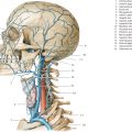
  Fig. 5.1d Lateral view of the brain of the same head as in a and b. The sections of the bicommissural series have been numbered as in a.
  Fig. 5.2 1st bicommissural section. Fig. 5.2a Inferior view of the first section of the bicommissural MRI series. The blue line in the signet marks the position of the sectional plane at the craniocervical junction at the level of the condyle and the atlas (see ▶Fig. 5.1b). The three layers of the cervical fascia within the soft tissues of the head–neck junction have been color coded (green – superficial layer; orange – middle layer; pink – deep layer). Abbreviations listed in the legends correspond to names of fascial spaces (e.g., BS = buccal space; reproduced from Engelke C. Ganzkörper-Computertomographie. Spiral- und Multislice-CT. Stuttgart: Thieme; 2007). Spinal structures and spinal dura. Cervical fasciae and resulting spaces. Brain structures, blood vessels, and meninges.
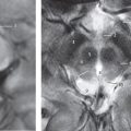
  Fig. 5.2b T2w MR image (TSE sequence) oriented in the bicommissural plane, identical to the sectional plane in a (since it is the corresponding basis of the schematic representation in a). Structures of the brain are accentuated by the selected sequence. The bicommissural MR series was obtained from a 33-year-old man. The blue line in the signet shows the course of the sectional plane through the spinal cord in the midline (▶Fig. 5.1c).
  Fig. 5.3 2nd bicommissural section. Fig. 5.3a Inferior view of the second section of the bicommissural series. The posterior cranial fossa has been sectioned just above the foramen magnum. The medulla oblongata and tonsils of cerebellum are seen in cut-section. Brain structures, blood vessels, and meninges.
  Fig. 5.3b T2w MR image oriented in the bicommissural plane, identical to the sectional plane in a.
  Fig. 5.4 3rd bicommissural section. Fig. 5.4a View of the third section of the bicommissural MRI series. The sectional plane passes through the center of the lower margin of the eyeball, temporomandibular joints, and obliquely through the junction of the pons and medulla oblongata. Brain structures, blood vessels, and meninges.
  Fig. 5.4b T2w MR image oriented in the bicommissural plane, identical to the sectional plane in a.
  Fig. 5.5 4th bicommissural section. Fig. 5.5a View of the fourth section of the bicommissural series. The temporal lobe has been sectioned in the middle cranial fossa while the pons and cerebellum have been sliced in the posterior cranial fossa. Brain structures, blood vessels, and meninges.
  Fig. 5.5b T2w MR image oriented in the bicommissural plane, identical to the sectional plane in a.
  Fig. 5.6 5th bicommissural section. Fig. 5.6a View of the fifth section of the bicommissural series. The sectional plane lies at the level of the entrance to the sella. On the left of the anterior cranial fossa, the olfactory bulb and tract have been indicated by a dotted line as located in the slice. These parts of the olfactory system lie in the olfactory groove. The frontal lobe, temporal lobe, infundibulum, mesencephalon, and cerebellum have been sectioned. Brain structures, blood vessels, and meninges.
  Fig. 5.6b T2w MR image oriented in the bicommissural plane, identical to the sectional plane in a.
  Fig. 5.7 6th bicommissural section. Fig. 5.7a View of the sixth section of the bicommissural series. The frontal lobe, temporal lobe, hypothalamus, midbrain, cerebellum, and occipital lobe are seen in cut-section in this plane. Brain structures, blood vessels, and meninges.
  Fig. 5.7b T2w MR image oriented in the bicommissural plane, with a sectional plane identical to that in a.
  Fig. 5.8 7th bicommissural section. Fig. 5.8a View of the seventh section of the bicommissural series. The striatum (putamen and caudate nucleus), hypothalamus, and inferior thalamus have been depicted. Only a small part of the infratentorial region is still included in this section. Brain structures, blood vessels, and meninges.
  Fig. 5.8b T2w MR image oriented in the bicommissural plane, identical to the sectional plane in a.
  Fig. 5.9 9th bicommissural section. Fig. 5.9a View of the ninth section of the bicommissural series. The insula reaches its largest expanse in this section. The sectional plane also passes through the striatum (putamen and caudate nucleus), internal capsule, and thalamus. Brain structures, blood vessels, and meninges.
  Fig. 5.9b T2w MR image oriented in the bicommissural plane, corresponding exactly to the selected sectional plane in a.
  Fig. 5.9c T1w view detail of the eighth section of the bicommissural series. The basal ganglial regions are well demarcated from each other on the T1w sequence.
  Fig. 5.10 9th bicommissural section. Fig. 5.10a View of the ninth section of the bicommissural series. The sectional plane separates the falx cerebri into anterior and posterior parts. The superior part of the insula has been sectioned. The splenium of the corpus callosum is located between the collateral trigone of the right and left ventricles. Brain structures, blood vessels, and meninges.
  Fig. 5.10b T2w MR image oriented in the bicommissural plane, corresponding exactly to the selected sectional plane in a.
  Fig. 5.10c Detail section of a transverse 7T-T2w MR image. The area striata is well delineated (the so-called Gennari stripe; arrows) and is as hyperintense as the cortex. (With kind permission of Prof. Forsting, University Hospital, Essen, Germany.)
  Fig. 5.11 10th bicommissural section. Fig. 5.11a View of the 10th section of the bicommissural series. The sectional plane divides the falx cerebri into anterior and posterior parts, with the supracommissural part of the cingulate gyrus lying in between, partially obscuring the corpus callosum. Brain structures, blood vessels, and meninges.
  Fig. 5.11b T2w MR image oriented in the bicommissural plane, corresponding exactly to the selected sectional plane in a.
  Fig. 5.12 11th bicommissural section. Fig. 5.12a View of the 11th section of the bicommissural series. The cingulate sulcus has been sliced tangentially in the sectional plane. The falx cerebri separates the left and right hemispheres. The inferior edge of the falx cerebri runs through the middle of the slice and is not seen in the illustration. Brain structures, blood vessels, and meninges.
  Fig. 5.12b T2w MR image oriented in the bicommissural plane, corresponding exactly to the selected sectional plane in a.
  Fig. 5.13 12th bicommissural section. Fig. 5.13a View of the 12th section of the bicommissural series. The falx cerebri separates the left hemisphere from the right completely in this slice and lies above the cingulate gyrus. Brain structures, blood vessels, and meninges.
  Fig. 5.13b T2w MR image oriented in the bicommissural plane, corresponding exactly to the selected sectional plane in a.
  Fig. 5.14 13th bicommissural section. Fig. 5.14a View of the 13th section of the bicommissural series. The central sulcus separates the frontal lobe from the parietal lobe. Brain structures, blood vessels, and meninges.
  Fig. 5.14b T2w MR image oriented in the bicommissural plane, corresponding exactly to the selected sectional plane in a.
  Fig. 5.15 14th bicommissural section. Fig. 5.15a View of the 14th section of the bicommissural series. The central sulcus lies about 5 cm posterior to the bregma. Brain structures, blood vessels, and meninges.
  Fig. 5.15b T2w MR image oriented in the bicommissural plane, lying in the selected sectional plane as in a.
  Fig. 5.16 Supraorbito-suboccipital sections. For specimen details see Chapter 12. DH = German horizontal Fig. 5.16a Illustration based on an X-ray image of the same head as in ▶Fig. 5.1. The 14 slices of the supraorbito-suboccipital series have been contiguously numbered with encircled digits from inferior to superior.
  Fig. 5.16b Median view of the brain of the same head as in a. The sections of the su praorbito-suboccipital series have been numbered as in ▶Fig. 5.1.
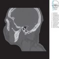
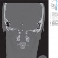
  Fig. 5.17 1st supraorbito-suboccipital section. Fig. 5.17a View of the 1st section of the supraorbito-suboccipital CT series. The sectional plane lies oblique to the foramen magnum just above the hypoglossal canal. The floor of the middle cranial fossa has been evenly sectioned. Brain structures, bone structures, and blood vessels.
  Fig. 5.17b Supraorbito-suboccipital oriented CT image of a 39-year-old woman from whom the other images of this series have also been obtained; for technical details see Chapter 12. The image corresponds exactly to the sectional plane in a (schematic representation based on respective CT images). Brain structures, bone structures, and blood vessels.
  Fig. 5.18 2nd supraorbito-suboccipital section. Fig. 5.18a View of the 2nd section of the supraorbito-suboccipital series. The sectional plane passes through the apical region of the orbit and through the medial aspects of the external auditory canals. The middle cranial fossa and the cerebellum have been sectioned. Brain structures, bone structures, and blood vessels.
  Fig. 5.18b Supraorbito-suboccipital oriented CT image, corresponding exactly to the sectional plane in a.
  Fig. 5.19 3rd supraorbito-suboccipital section. Fig. 5.19a View of the 3rd section of the supraorbito-suboccipital series. The sectional plane runs through the sella turcica and separates the dorsum sellae. The posterior cranial fossa is depicted with the left internal auditory canal. Brain structures, bony structures, and blood vessels.
  Fig. 5.19b Supraorbito-suboccipital oriented CT image, corresponding exactly to the sectional plane in a.
 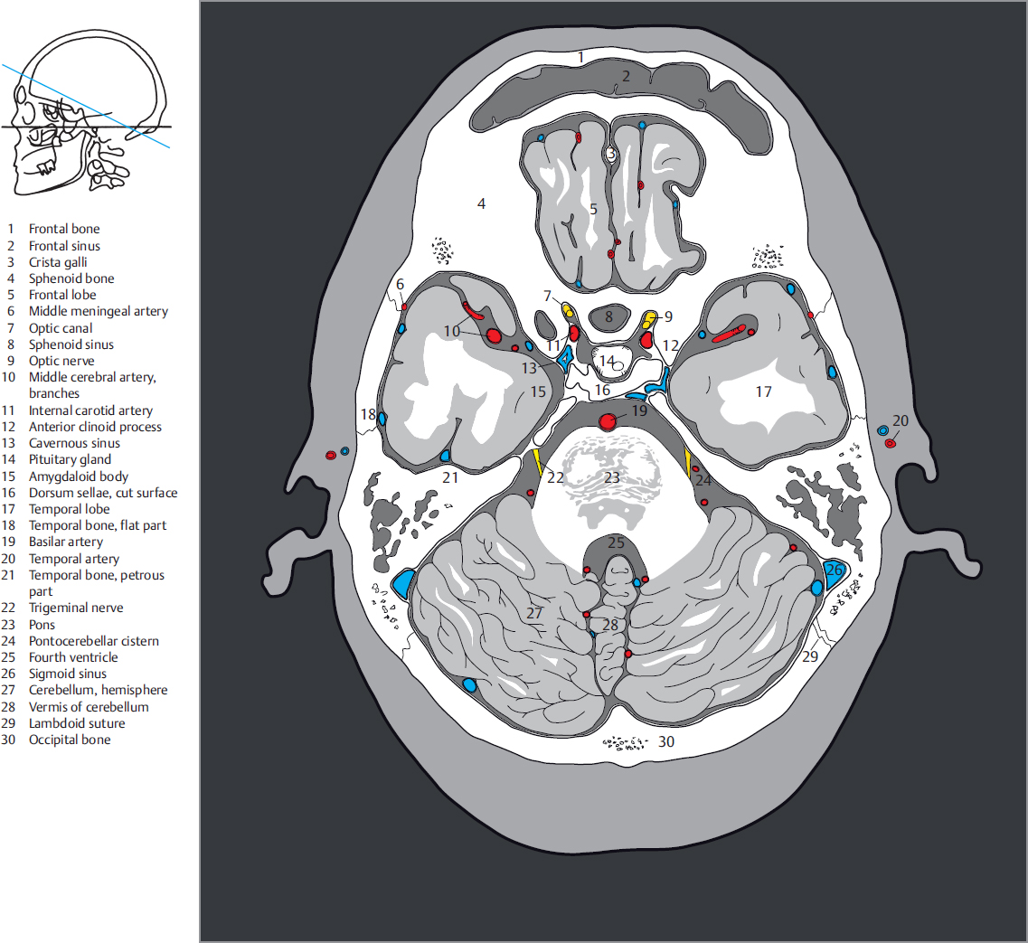 Fig. 5.20 4th supraorbito-suboccipital section. Fig. 5.20a View of the 4th section of the supraorbito-suboccipital series. The optic chiasma and the internal auditory canal have been sectioned in the slice. The sectional plane passes through the frontal lobe, temporal horns, and the cerebellum. Brain structures, bony structures, and blood vessels.
  Fig. 5.20b Supraorbito-suboccipital oriented CT image, lying exactly in the selected sectional plane as in a.
  Fig. 5.21 5th supraorbito-suboccipital section. Fig. 5.21a View of the 5th section of the supraorbito-suboccipital series. The image includes the circle of Willis, along with the anterior, middle, and posterior cranial fossae with their contents. The posterior cranial fossa is limited anteriorly by the sectioned tentorium of cerebellum. Brain structures, bony structures, and blood vessels.
  Fig. 5.21b Supraorbito-suboccipital oriented CT image, lying exactly in the selected sectional plane as in a.
  Fig. 5.22 6th supraorbito-suboccipital section. Fig. 5.22a View of the 6th section of the supraorbito-suboccipital series. Parts of the anterior horns of the lateral ventricles lie in this plane. The IIIrd ventricle has been sectioned at its opening into the aqueduct of the midbrain. The inferior horns of the lateral ventricles have also been depicted. The anterior part of the tentorium of cerebellum has been sectioned. Brain structures, bony structures, and blood vessels.
  Fig. 5.22b Supraorbito-suboccipital oriented CT image, lying exactly in the selected sectional plane as in a.
  Fig. 5.23 7th supraorbito-suboccipital section. Fig. 5.23a View of the 7th section of the supraorbito-suboccipital series. The sectional plane runs through the anterior horns of the lateral ventricles and the IIIrd ventricle. The quadrigeminal plate has been sectioned. Brain structures, bony structures, and blood vessels.
  Fig. 5.23b Supraorbito-suboccipital oriented CT image, lying exactly in the selected sectional plane as in a.
  Fig. 5.24 8th supraorbito-suboccipital section. Fig. 5.24a View of the 8th section of the supraorbito-suboccipital series. The sectional plane touches the lateral ventricles and slices the posterior horns just below the collateral trigone of the lateral ventricle. Brain structures, bony structures, and blood vessels.
  Fig. 5.24b Supraorbito-suboccipital oriented CT image, lying exactly in the selected sectional plane as in a.
  Fig. 5.25 9th supraorbito-suboccipital section. Fig. 5.25a View of the 9th section of the supraorbito-suboccipital series. The thalamus and the collateral trigone of the lateral ventricle have been sectioned. Brain structures, bony structures, and blood vessels.
  Fig. 5.25b Supraorbito-suboccipital oriented CT image, lying exactly in the selected sectional plane as in a.
  Fig. 5.26 10th supraorbito-suboccipital section. Fig. 5.26a View of the 10th section of the supraorbito-suboccipital series. The corpus callosum builds the roof of the lateral ventricles which are still seen in the slice. Brain structures, bony structures, and blood vessels.
  Fig. 5.26b Supraorbito-suboccipital oriented CT image, lying exactly in the selected sectional plane as in a.
  Fig. 5.27 11th supraorbito-suboccipital section. Fig. 5.27a View of the 11th section of the supraorbito-suboccipital series. The sectional plane lies above the corpus callosum. Bony structures and blood vessels.
  Fig. 5.27b Supraorbito-suboccipital oriented CT image, lying exactly in the selected sectional plane as in a.
  Fig. 5.28 12th supraorbito-suboccipital section. Fig. 5.28a View of the 12th section of the supraorbito-suboccipital series. The sectional plane lies above the cingulate gyrus. Brain structures, bony structures, and blood vessels.
  Fig. 5.28b Supraorbito-suboccipital oriented CT image, lying exactly in the selected sectional plane as in a.
  Fig. 5.29 13th supraorbito-suboccipital section. Fig. 5.29a View of the 13th section of the supraorbito-suboccipital series. The sectional plane lies just beneath the cranial vault. Brain structures, bony structures, and blood vessels.
  Fig. 5.29b Supraorbito-suboccipital oriented CT image, lying exactly in the selected sectional plane as in a.
  Fig. 5.30 14th supraorbito-suboccipital section. Fig. 5.30a View of the 14th section of the supraorbito-suboccipital series. The sectional plane lies directly beneath the cranial vault. Brain structures, bony structures, and blood vessels.
  Fig. 5.30b Supraorbito-suboccipital oriented CT image, lying exactly in the selected sectional plane as in a.
  Fig. 5.31 Transverse image of the base of skull. CT image of the base of the skull, oriented perpendicular to the Meynert axis. This and the following images were reconstructed from a thin-section transverse data set of a diagnostic examination. Bony landmarks in this image are the turbinates, maxillary sinuses, the mastoid, and the occipital bone.
  Fig. 5.32 Transverse image of the base of skull. CT image of the base of the skull, oriented perpendicular to the Meynert axis. Bony landmarks are the nasal bone, the nasal septum, and the petrous part of temporal bone. Exits of the V/3 cranial nerve and the middle meningeal artery have been depicted.
  Fig. 5.33 Transverse image of the base of skull. CT image of the base of the skull, oriented perpendicular to the Meynert axis. The medial and lateral walls of the orbit have been sectioned. The sphenoid bone forms the floor of the middle cranial fossa. The occipital bone surrounds the posterior cranial fossa. Exits of the internal carotid artery and the V/3 and VIIth cranial nerves have been depicted.
  Fig. 5.34 Transverse image of the base of skull. CT image of the base of the skull, oriented perpendicular to the Meynert axis. The inferior aspect of the orbit and the sphenoid sinus as well as the middle cranial fossa, exit of the V/2 cranial nerve, the petrous part of the temporal bone, and the posterior cranial fossa can be identified.
  Fig. 5.35 Transverse image of the base of skull. CT image of the base of the skull, oriented perpendicular to the Meynert axis. The center of the orbit, ethmoid air cells, the dorsum sellae, and the superior orbital fissures have been sectioned.
  Fig. 5.36 Transverse image of the base of skull. CT image of the base of the skull, oriented perpendicular to the Meynert axis. The cranial vault forms an oval bony ring. The anterior cranial fossa has been sectioned with the olfactory groove/ethmoid fossa.
  Fig. 5.37 Schematic 3D representation of the base of the skull. Bony exits for nerves and vessels of the central base of the skull are especially well seen. Exit points have been highlighted in bold in the captions, anatomic structures in following captions pass through them. An exit has been labelled as (a) or (b) if it is seen in one of two views. Exits to the pterygopalatine fossa have been indicated with an asterisk (*). (Reproduced from Schuenke, Schulte, and Schumacher, Atlas of Anatomy, 3rd edition, ©2012, Thieme Publishers, New York. Illustration by Karl Wesker/Markus Voll.) Fig. 5.37a Intracranial 3D view of the base of the skull.
  Fig. 5.37b External 3D view of the base of the skull.