6
Musculoskeletal System
Carol A. Boles
 Chapter Outline
Congenital and Developmental Anomalies
Gout, Pseudogout, and Hemophilic Arthritis
Approach to Common Clinical Problems
NORMAL DEVELOPMENT
Bones are visible on nearly all radiographs; therefore, radiologic anatomy of the musculoskeletal system is extremely important, but it can be time consuming to learn. Entire textbooks are dedicated to specific joints, but a solid knowledge of normal anatomy is a prerequisite for intelligent image evaluation. Despite many advances in imaging using other modalities such as computed tomography (CT), magnetic resonance (MR) imaging, and ultrasound, radiographs remain the mainstay of musculoskeletal imaging. Anatomy is anatomy no matter how you look at it and imaging is less confusing when thought of in this way. Let us begin with a general overview and then normal image anatomy of the hand and move systematically cephalad to the shoulder girdle. This will be followed by normal image anatomy of the lower extremity from the foot to the hip.
The bones develop in a rather systematic fashion. Bone formation is by either intramembranous (transformation of mesenchymal tissue) or endochondral (conversion of an intermediate cartilage form) formation, or by both methods.
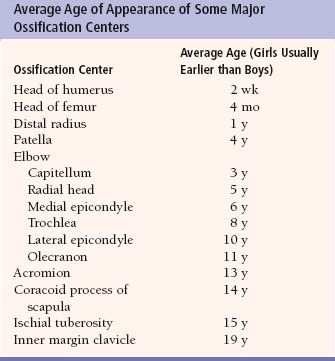
Many flat bones, such as the skull and mandible, form by intramembranous bone formation. Both methods are found in the extremities, spine, and pelvis. With endochondral ossification, cartilage is replaced by bone initiated at specific sites called centers of ossification. These centers of ossification appear in such a predictable order that they may be used for estimation of age (Table 6.1). Understanding this aids in evaluation of fractures in the pediatric population as a small bone adjacent to a joint potentially may be assumed to be an ossification center when it is, in fact, a fracture. The area of cartilage between the centers of ossification is called the growth plate or physis. Eventually, the centers of ossification fuse across the physes.
Joints develop between the ends of bones. There are three types of joints: Synchondrosis, symphysis, and synovial joints. A synchondrosis has hyaline cartilage between the ends of bone and not movable while symphysis joints have fibrocartilage and a small amount of motion. Synovial joints, typically thought of as a “joint,” have a hyaline cartilage covering and synovium, which produces fluid to lubricate these movable joints.
As a brief reminder of radiographic terminology, anteroposterior (AP) radiographs are named by the direction the x-ray beam travels through the body part, assuming the person is in anatomic position. For example, anatomic position has the arms at the sides with palms facing forward. The typical hand radiograph places a hand, palm down on the radiographic plate and the x-ray beam enters through the posterior (dorsal) side of the hand to reach the plate; this is a posteroanterior (PA) radiograph. The foot, however, when radiographed with the plantar surface (sole of the foot) on the radiographic plate is an AP radiograph. This is somewhat of a misnomer since the dorsal surface of the foot is really the cephalic surface of the foot in anatomic position.
Upper Extremity
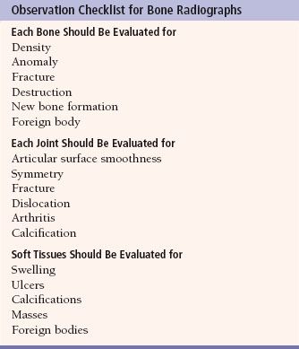
People commonly injure their extremities because they actively encounter the environment with their arms and legs. Consequently, you will probably order many radiographs of the extremities in your clinical practice. Thus, we need a system to evaluate upper and lower extremity images (Table 6.2). Each bone in an image must be carefully evaluated for density, variations of normal, and fracture. Also, each joint must be evaluated for width, smoothness of the articular surfaces, dislocation, arthritis, fracture, and foreign body. The soft tissues should be evaluated for edema, hemorrhage, masses, calcifications, and foreign bodies.
The hand is so complex that it is a subspecialty in both orthopedics and plastic surgery. When you request radiographs of the hand, the standard study usually consists of PA, oblique, and lateral views (Fig. 6.1). Remember that one of the most difficult aspects of medicine is to learn the jargon and routines, so we need to get the hand terminology correct from the beginning. Each digit of the hand must be properly named to communicate and document information accurately. The proper terminology for each digit and the numbering system for the metacarpals are displayed in Figure 6.1A. Simply numbering the digits does not suffice, especially in situations in which digits are missing. Would you refer to the index finger as the first or second finger when the thumb is missing? So, beginning on the radial side of the hand, the thumb is always the thumb and not the first finger. Next is the index finger (not the second finger and not the first finger as some say there are four fingers and a thumb). Following are the long finger (not the third), the ring finger (not the fourth), and the small or little finger (not the fifth).
Table 6.2
Metacarpals (Fig. 6.1A) are numbered logically with the thumb articulating with the first metacarpal, the index finger with the second metacarpal, and so on. As a general rule, each hand digit has three phalanges except the thumb, which has only two. The phalanges are named proximal, middle, and distal. The joint between the proximal phalanx and the metacarpal is called the metacarpophalangeal (MCP) joint (Fig. 6.1A). The joint between the proximal and middle phalanges is the proximal interphalangeal (PIP) joint. The joint between the distal and middle phalanges is called the distal interphalangeal (DIP) joint. The thumb, with only two phalanges, has an interphalangeal joint. The distal-most aspect of the metacarpals and the phalanges is the head, whereas the proximal portions are the bases. The central aspects of these bones are the shafts.
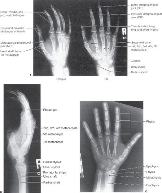
FIGURE 6.1. A: Right-hand oblique and posteroanterior (PA) radiographs. Normal. B: Right-hand lateral radiograph. Normal. C: Left-hand PA radiograph. Normal physis, epiphysis, metaphysis, and diaphysis. The cartilaginous physis is a lucent area on a radiograph.
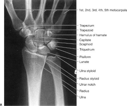
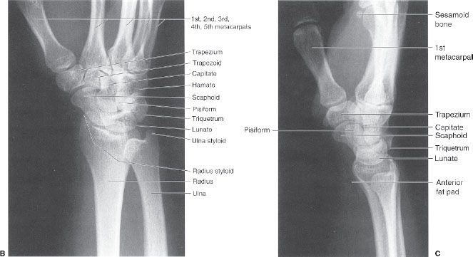
FIGURE 6.2. Right wrist PA (A), oblique (B), and lateral (C) radiographs. Normal. Notice that the tip of the radial styloid is distal to the tip of the ulnar styloid and the radius articulates distally with the scaphoid and lunate carpals and laterally with the ulna (ulnar or sigmoid notch). The distal radial articular surface slopes toward the ulna and anteriorly (palmar). The distal ulna articulates with the radius laterally and wrist fibrocartilage distally. The ulna does not articulate directly with a carpal.
Commonly used bone terms such as physis, epiphysis, metaphysis, and diaphysis can be confusing to the novice, but actually they are very simple. The locations of these entities are demonstrated in Figure 6.1C). The physis (physeal or epiphyseal plate) is the growth plate as bone formation occurs here. The epiphysis is the end of a long bone and contains a secondary ossification center. The physis, being mostly cartilage is the lucent part of a child’s bone on a radiograph and is the weakest part of a growing bone. The diaphysis (bone shaft, primary ossification center) is the long, thin center of a long bone and the metaphysis is located between the diaphysis and the physis. The term apophysis is confusing and merely refers to a secondary ossification center that does not articulate with another bone and does not contribute to bone length growth (as an epiphysis does), but, rather, to bone contour. A typical example is the greater trochanter as seen in Figure 6.23.
The wrist and forearm are common fracture sites, especially in children. If we are to understand and treat fractures in these areas, a thorough knowledge of wrist and forearm anatomy is very important. The appearance, location, and names of each carpal bone must be learned as well as their relationship to the distal radius and ulna. These relationships are well visualized on standard PA, lateral, and oblique radiographic views of the wrist (Fig. 6.2).
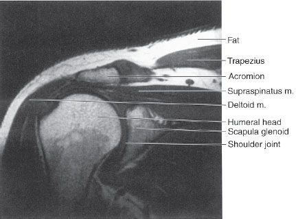
We generally obtain AP and lateral views of the forearm in children and adults (Fig. 6.3). Routine elbow radiographs consist of AP and lateral views (Fig. 6.4), but external rotation oblique views of the elbow may be requested on occasion (similar to the appearance in Figure 6.5A). Radiographs of the humerus usually consist of AP (Fig. 6.5A) and lateral views. Generally, an AP radiograph is obtained to evaluate the shoulder (Fig. 6.5B) and this is supplemented by either an axillary or lateral view of the shoulder depending on local practice. Musculoskeletal anatomy and disease can be nicely demonstrated by CT and MRI (Table 6.3). CT imaging is especially good for bone detail, whereas MRI is good for soft tissue and bone marrow imaging, revealing edema caused by bone contusions or subtle fractures not seen on the radiographs. MRI is especially helpful in displaying the soft tissue structures around joints such as shoulder rotator cuff anatomy (Fig. 6.6).
Table 6.3
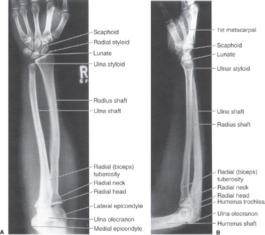
FIGURE 6.3. Right forearm AP (A) and lateral (B) radiographs. Normal. Note that in the correct lateral of the forearm, both the elbow and the wrist are in the lateral position. The distal radius is large and the proximal radius is small, whereas the distal ulna is small and the proximal ulna is large. The radius is far more important than the ulna in the wrist joint, whereas the ulna is more important in the elbow joint than the radius.
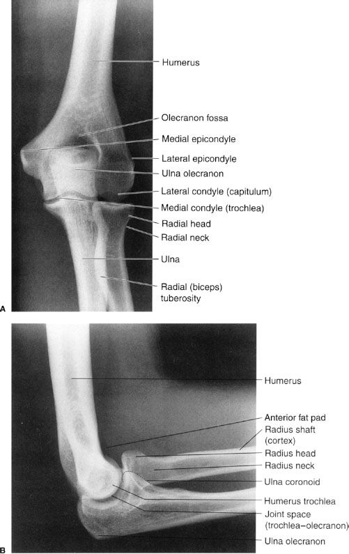
FIGURE 6.4. Left elbow AP (A) and lateral (B) radiographs. Normal. The elbow is usually flexed 90 degrees to minimize the appearance of the anterior and posterior fat pads. The dotted line on B indicates the ulna coronoid process.
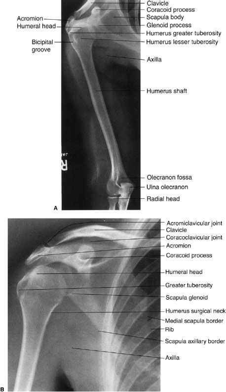
FIGURE 6.5. A: Right humerus AP radiograph with external rotation of the humerus. Normal. The right elbow is in an oblique position. B: Right shoulder AP radiograph with external rotation of the humerus. Normal. Note the prominence of the greater tuberosity.
Lower Extremity
Now we approach lower extremity radiologic imaging by beginning with the foot and moving toward the hip. The standard views of the foot are AP, lateral, and oblique (Fig. 6.7). Naming of the toes is far easier than that of the fingers. The big toe or great toe may be referred to as the first toe and the remaining toes are numbered sequentially ending with the little or the fifth toe. Similarly, the metatarsals are numbered sequentially with the great toe articulating with the first metatarsal, the second toe articulating with the second metatarsal, and so forth. The ankle is usually imaged by AP-, lateral-, and, either, oblique- or mortise-view (a 10-degree internally rotated view) radiographs (Fig. 6.8). MRI may be used to image the ankle to detect soft tissue injury (Fig. 6.9). Radiographs of the tibia and fibula usually consist of AP and lateral views (Fig. 6.10).
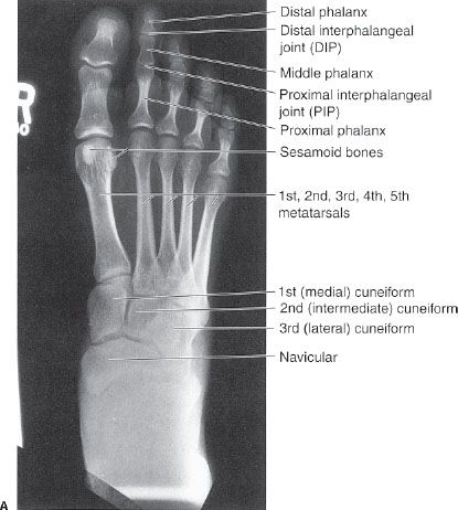
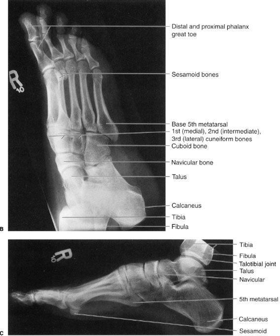
FIGURE 6.7. Right foot AP (A), oblique (B), and lateral (C) radiographs. Normal.
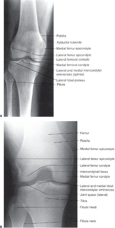
Routine knee radiographs consist of AP and lateral views and they may be supplemented by AP standing radiographs (Fig. 6.11) and/or oblique views. Axial, coronal, and sagittal magnetic resonance (MR) images of the knee (Fig. 6.12) are commonly requested to evaluate injuries of the knee, particularly, the nonosseous structures, including the medial and lateral menisci, articular cartilage, ligaments, tendons, and muscles. Remember that ligaments, tendons, and vessels have a low-intensity signal or appear black on MR images.
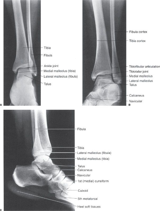
FIGURE 6.8. Left ankle AP (A), oblique/mortise (B), and lateral (C) radiographs. Normal. Note how the mortise view (B) allows improved visualization of the distal tibiofibular articulation.
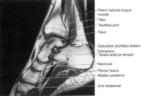
FIGURE 6.9. Right ankle sagittal T1 MR image. Normal. Note that the calcaneal (Achilles) tendon has a homogeneous low-intensity (black) signal.
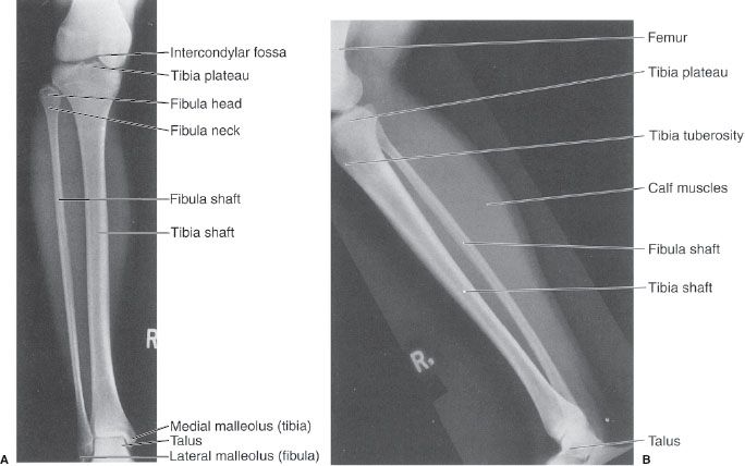
FIGURE 6.10. Right tibiofibular AP (A) and lateral (B) radiographs. Normal.
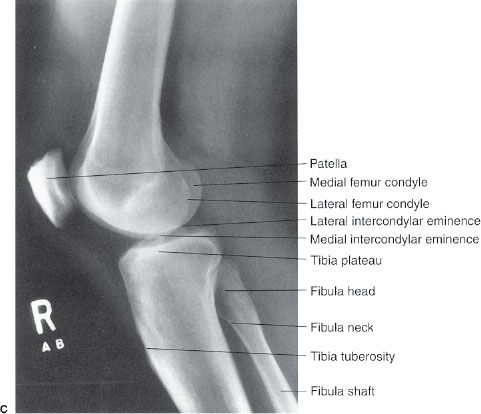
The femur and the hip joint are radiographed in the AP and lateral views (Fig. 6.13). A cross-table lateral view of the hip is frequently obtained in a trauma setting as seen in Figure 6.68B.
VARIATIONS OF NORMAL
There are several osseous variations of normal that can cause confusion for the novice (Table 6.4). One such variation of normal is the sesamoid bone, which is merely a normal extra bone, usually within a tendon. Sesamoids occur at numerous sites and are commonly found in the plantar aspect of the foot near the head of the first metatarsal (see Fig. 6.7) and in the palmar aspect of the hand near the head of the first and sometimes other metacarpals (Fig. 6.14A–C; Fig 6.1A), where they are actually located in the volar plate rather than in a tendon. When you think about it, the patella is actually a sesamoid bone or a bone within a tendon. Sesamoids function to decrease the moment arm and thus, the work of a muscle. Thus, the quadriceps group of muscles becomes hypertrophied to compensate for increased work following the removal of the patella.
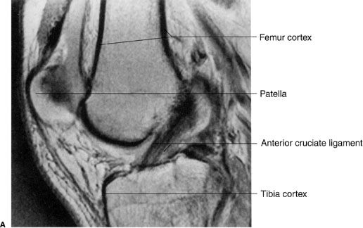
FIGURE 6.12. A: Right knee proton-dense sagittal MR image. Normal anterior cruciate ligament in a 36-year-old man.
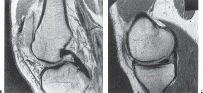
FIGURE 6.12. B: Right knee proton-dense sagittal MR image in the same patient. Normal posterior cruciate ligament. The posterior cruciate ligament (arrow) is more homogeneous and has a lower-intensity signal (blacker) than the anterior cruciate ligament. C: Right knee proton-dense medial-sagittal MR image in a 32-year-old man. Normal posterior horn (straight arrow) and anterior horn (curved arrow) of the medial meniscus.
Ossicles are another variant of normal. They are small, supernumerary or extra bones found in a variety of places in juxtaposition to the skeletal system and usually named after the neighboring bone (Fig. 6.14D). The bipartite or multipartite patella (Fig. 6.14E–G) is another example of an accessory bone that should not be mistaken for a fracture. The condition results when one or more of the patellar ossification centers fail to fuse with the main patellar body. The result is that the patella has two or more sections and this male predominant variant occurs superolaterally approximately 75% of the time. Epiphyses can vary in appearance and in their number of ossification centers and still be normal (Fig. 6.14H, I). A sometimes confusing variant is a prominent scaphoid tubercle. This prominence can be mistaken for a fracture by even experienced clinicians.
Table 6.4
Normal Osseous Variations
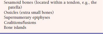
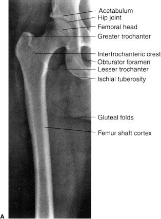
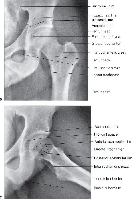
FIGURE 6.13. A: Right hip and proximal femur AP radiograph. Normal. Left hip AP (B) and frog-leg lateral (C) radiographs. Normal. See Figure 6.68B for a true lateral of the hip.
CONGENITAL AND DEVELOPMENTAL ANOMALIES
Osseous congenital anomalies are not uncommon and a few of the many variations are listed in Table 6.5 and shown in Figures 6.15 to 6.20.
Coalition refers to the failure of segmentation of bones during development, resulting in a congenital fusion. This fusion may be bony or fibrous. Common locations involve the lunate and triquetrum in the wrist (see Fig. 6.15) and the calcaneus and navicular or the calcaneus and talus in the foot (see Fig. 6.16).
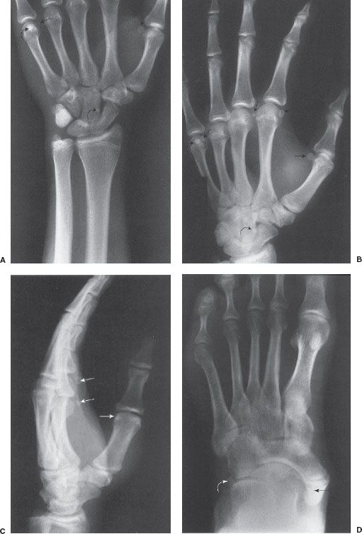
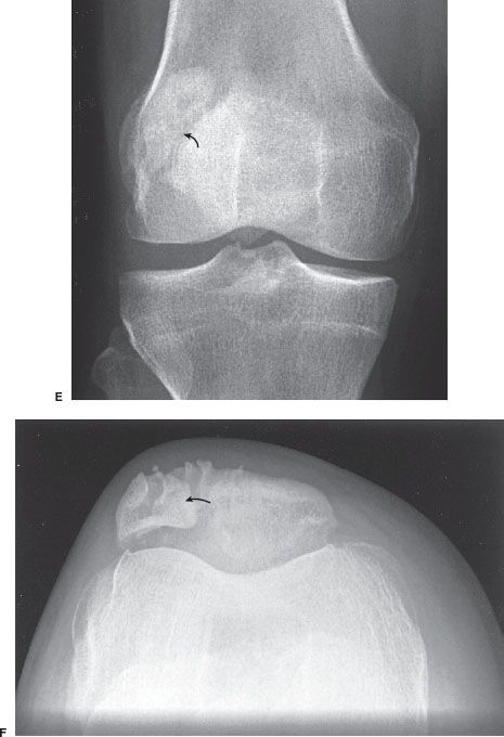
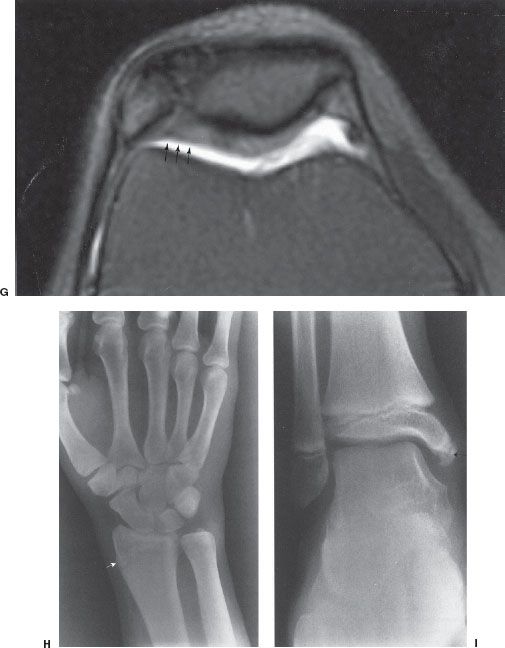
FIGURE 6.14. Left wrist PA (A), left-hand oblique (B), and lateral (C) radiographs. Multiple sesamoids (straight arrows). Bone islands (curved arrows) are present in the head of the fifth metacarpal and the capitate, and they have no clinical significance. D: Left foot AP radiograph. Os tibiale externum (black arrow) and os peroneum (white arrow). Right knee anterior radiograph (E), tangential radiograph of right patella (F), and axial fat-suppressed MR image (G). Bipartite patella. Note that the patella has two sections, and the accessory bone (arrows) usually lies superior and lateral to the main body of the patella. G: The axial image shows the continuous cartilage over the ossification center (arrows) differentiating it from a fracture, which is rare in this superolateral position. H: Right wrist PA radiograph. Normal distal right radial epiphysis spur. This 21-year-old woman fell and had a painful wrist. This spur (arrow) is a variant of normal and must not be confused with a fracture. I: Right ankle AP radiograph. Accessory epiphysis near the tip of the distal tibia epiphysis in the region of the medial malleolus (arrow). This is a variant of normal.
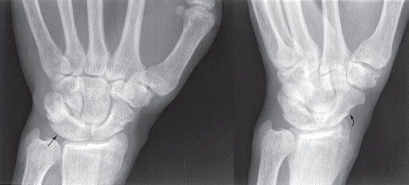
FIGURE 6.15. Left wrist PA and oblique radiographs. Congenital fusion. There is coalition of the lunate and triquetrum (straight arrow) and a prominent scaphoid tubercle (curved arrow). This tubercle should not be confused with a fracture. Compare with the normal carpals in Figure 6.2.
Osteogenesis imperfecta is a congenital, nonsex-linked, hereditary abnormality with several variants of primary defects in collagen synthesis causing deficient bone matrix. These patients have bones (Fig. 6.20) that are fragile, fracture easily, and are often deformed. Achondroplasia is a hereditary, often caused by spontaneous mutation, autosomal-dominant anomaly manifested by shortened long bones which results in this quite common form of dwarfism (Fig. 6.21).
The hip joint is the most common site of congenital dislocation and there is a strong female predominance. Developmental dysplasia of the hip (DDH), formerly known as congenital dislocation of the hip or congenital hip dysplasia (Fig. 6.22) is usually diagnosed in infancy. DDH is an acquired abnormal development of the hip joint resulting in an abnormal acetabulum and femoral head owing to displacement of the femoral head deforming the acetabular cartilage. The femoral head usually displaces superiorly but can displace posteriorly. The acetabulum becomes shallow and the angle of the femoral neck between the femoral head and shaft is widened.
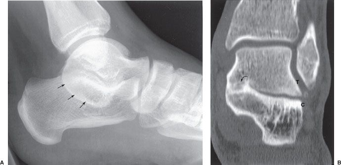
FIGURE 6.16. Lateral radiograph of the left ankle (A) and coronal CT image (B). There is a prominent C on the radiograph (arrows). Compare with the normal lateral in Figure 6.8. The coronal CT clearly shows continuous bone bridging (arrow) between the talus (T) and calcaneus (C).
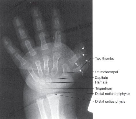
FIGURE 6.17. Left-hand PA radiograph (child). Polydactylism. There are two thumbs and one first metacarpal. One thumb has three phalanges (straight arrows) and the other thumb has two phalanges (curved arrows).
FIGURE 6.18. Left forearm pronated, oblique radiograph. Absence of the radius, first metacarpal, and thumb. This 6-year-old had left hand and arm deformity at birth.
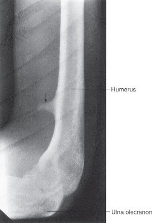
FIGURE 6.19. Right humerus lateral radiograph. Supracondylar process or spur (arrow). It is usually located in the anteromedial aspect of the distal humerus.
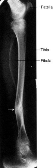
FIGURE 6.20. Left tibia and fibula lateral radiograph. Osteogenesis imperfecta. There is a healing, apex posterior, left tibia fracture (arrow). Note the thin serpentine appearance of the fibula and generalized osteoporosis.
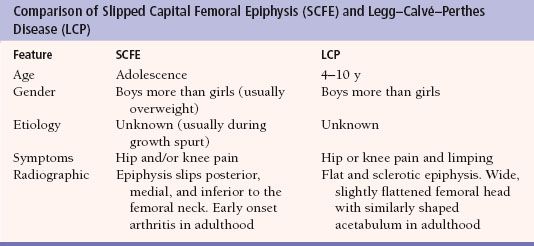
Two hip problems that can cause confusion are slipped capital femoral epiphysis (SCFE) and Legg–Calvé–Perthes disease (Table 6.6). SCFE (Fig. 6.23) is a hip problem that occurs during adolescence and is often associated with hip pain. The etiology is not understood, but there may be a history of trauma. It is more common in boys than girls and those who are overweight. Apparently, the physis becomes weakened during the rapid growth around puberty. The radiographic findings show the femoral head slipping or displacing posteriorly, medially, and inferiorly relative to the femoral neck. The proximal epiphysis becomes widened. Mild cases may go undetected and present with an earlier-than-expected onset of osteoarthritis.
Table 6.5
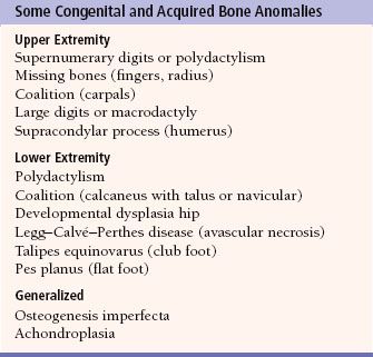
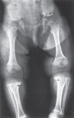
FIGURE 6.21. Pelvis and lower extremities AP radiograph. Achondroplasia. The proximal long bones are shorter and wider than normal, especially the proximal tibias (straight arrows). The iliac bones are rounded and the acetabula are flat (curved arrow).
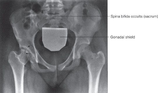
FIGURE 6.22. Pelvis AP radiograph. Developmental dysplasia of the right hip in a 14-year-old. The right hip is abnormal with a flattened femoral head (straight arrow) and a poorly formed acetabulum (curved arrow). Compare the right hip to the normal left hip and note how the femoral heads remodel to conform to the shape of their corresponding acetabulum.
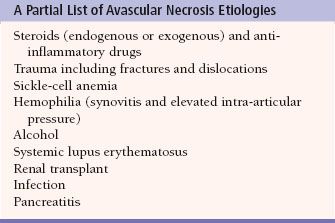
Legg–Calvé–Perthes disease (Fig. 6.24A) is a form of avascular necrosis (AVN), and the etiology is unknown. It may be referred to as osteochondrosis or coxa plana. It typically occurs in a boy between 3 and 10 years of age who complains of hip pain and walks with a limp. The hip pain may be referred to the ipsilateral knee. Radiographic findings vary but may include increased density of the femoral capital epiphysis, femoral head flattening, rarefaction (bone demineralization) of the metaphysis, and medial joint space narrowing. In general, AVN, osteonecrosis, or aseptic necrosis can occur in any joint (Fig. 6.24B, C) and can result from multiple other etiologies. Some of the other causes of AVN are listed in Table 6.7. The typical findings are sclerotic bone changes on one side of a joint that may go on to fracture, fragmentation, and eventually to collapse. MRI (Fig. 6.24C) has proved particularly useful for the diagnosis of AVN assisting in decisions for initiation of treatment prior to radiographic changes and predicting subsequent long-term complications such as early onset of arthritis.
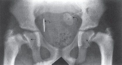
FIGURE 6.23. Pelvis AP radiograph. Bilateral slipped capital femoral epiphyses (SCFE) in a 15-year-old with chronic renal failure and on dialysis. The capital (proximal) femoral epiphyses (straight arrows) are displaced from their normal anatomic position. Usually, they are displaced inferiorly and posteromedially. There are monitoring electrodes projecting over the pelvis (curved arrows).
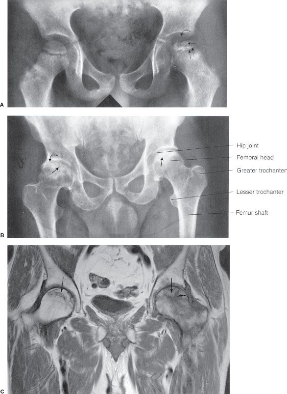
FIGURE 6.24. A: Pelvis AP radiograph. Legg–Calvé–Perthes disease. The right femoral head is normal. Note the irregular contour, flattened articular surface, and increased density of the left femoral head (single straight arrow). The left hip joint space is widened (curved arrow). The left proximal femoral epiphysis is widened (double straight arrows), and the metaphysis is irregular. Note that the acetabulum is normal. B: Pelvis AP radiograph. Bilateral femoral head avascular necrosis of unknown etiology in a 42-year-old man. Both femoral heads (straight arrows) are sclerotic in appearance, and the right femoral head is deformed because of mild collapse or fracture. The right hip joint is narrowed laterally (curved arrow). C: Coronal T1-weighted MRI. Femoral head osteonecrosis in a patient on chronic steroids. The crescentic area formed by low-signal lines (straight arrows) represents the infarcted regions. The left hip has a large amount of low-signal edema (curved arrow), suggesting a more acute infarction.
TRAUMA
Fractures and Dislocations
Extremity fractures are very common, so now is the time to discuss fractures in general. The initial imaging modality to evaluate for fracture should be a radiograph. Because a fracture or other osseous abnormality may be visible on only one of the radiographs, we obtain at least two views of a bone or joint which are 90 degrees opposed to each other. Give yourself every opportunity to detect a fracture or other abnormality by obtaining as many views of an area as is practical. Never accept just one radiographic view of a bone or joint. When there is persistent concern for a fracture and the radiographs are normal, a clinical assessment is then needed. In many circumstances, the area of concern can be immobilized for a week and repeat radiographs obtained to see whether an occult fracture has now become visible. Other fractures are of such clinical importance that it is important to find out right away. The classic example is a hip fracture in an elderly patient for which an MRI should be obtained if the initial radiographs do not demonstrate a fracture. Some clinicians may get a CT scan of the hip because it is more readily available, but be wary of a negative scan in an elderly patient as these, too, may be falsely negative with a nondisplaced fracture. CT scans are, however, the screening method of choice for cervical spine fractures and are often used to better define fractures in many locations prior to treatment.
Table 6.7
There are other rules of thumb to keep in mind. Paired bones such as the radius and ulna rarely have an isolated fracture; look closely for an associated fracture or a dislocation of the other bone at its proximal or distal joint. Structures that function as a ring, such as the pelvis, the mandible (with the facial bones), or the bones surrounding the ankle joint, also usually fracture in more than one spot. There are several fracture patterns that are typical and common, learn to look closely at the common locations for fractures.
In general, fractures can be conveniently divided into two major clinical categories.
1. Closed fracture means that there are bone fragments and the skin is intact.
2. Open fracture means the skin is not intact near the fracture. An open fracture occurs when the skin has been penetrated by one or more of the bone fragments or by a penetrating foreign body.
Many terms applied to fractures are very descriptive and quite specific (Fig. 6.25A, B). Examples of straightforward common terms for describing fractures include the following.
• Simple. Two significant fracture fragments with a single fracture plane.
• Complex or comminuted, meaning the fracture ends are smashed into multiple large pieces. Tiny bone fragments are not considered fracture fragments because they are clinically irrelevant. A good way to think about this is to determine if a major tendon or ligament is attached or if the bone piece is large enough to secure with a screw, then they are comminuted fractures.
• Spiral, transverse, oblique.
• Nondisplaced.
• Overriding.
• Distracted.
• Angulated.
• Offset, or displacement, usually described by the percentage of the fracture fragments abutting or touching each other.
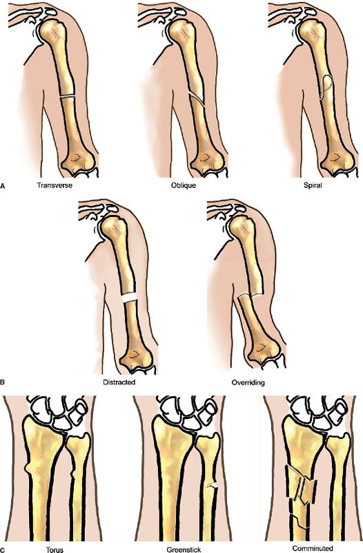
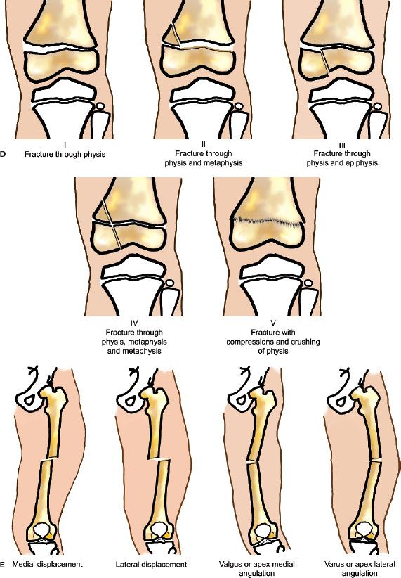
FIGURE 6.25. A,B: Some common fractures and the terms used to describe them and their alignment. C: Common descriptive terms for fractures which are not simple. Illustration by CBoles Art. D: The Salter–Harris classification of physis fractures. E: Illustrations of the nomenclature used to describe fracture displacement and angulation. Illustration by CBoles Art.
Some descriptive fracture terms (Fig. 6.25C) that are not quite so obvious include the following.
• Torus fracture (often involving the distal radius) looks like the bump at the base of a Greek column and has nothing to do with a bull. This is an incomplete fracture that occurs in children. The bump is created by a buckling of the flexible bone cortex without an obvious fracture line.
• Greenstick fracture describes a bone that fractures by bending like a green twig and is also incomplete.
• Pathologic fracture is one that passes through abnormal bone such as a metastasis, a primary bone tumor, or a bone cyst.
• Stress, or fatigue, fractures are secondary to unusual or excess stress, for example, tibial fractures in runners who overdo it.
• Insufficiency fractures describe fractures in bone with decreased strength, for example, caused by osteoporosis. Such a fracture may result from a normal stress such as merely walking across a room.
• An avulsion fracture is usually a fracture that occurs at the site of a tendon attachment. This fracture results when the tendon and muscle remain intact while the bone gives way (avulses) at the site of the tendon attachment to the bone.
The Salter–Harris classification of fractures (Fig. 6.25D) is helpful in describing and understanding fractures around a physis. The classification of basic five types has been expanded in recent years, but remains the standard. The higher the grade of Salter–Harris fracture, the more likely there is to be premature fusion of the growth plate. Remember that the physis represents the weakest point in a bone.
Type I: The fracture involves only the physis.
Type II: The fracture involves the physis and metaphysis and is the most common.
Type III: The fracture involves the physis and epiphysis.
Type IV: The fracture involves the physis, metaphysis, and epiphysis.
Type V: The fracture involves only the physis, but there is compression of the physis. This type is less common, but more serious than type 1 because there is a high risk of the physis fusing as the fracture heals. As a result, the bone stops growing and the limb is shorter than the opposite side.
When describing the position of displaced fracture fragments, we use another set of terms. Traditionally, the distal fragment is described relative to the proximal fragment. This means that if the distal part of the fracture is displaced toward the midline of the body, it is displaced medially. One may substitute medial with volar, dorsal, radial, ulnar, or any other appropriate direction of displacement. The same concept may be used to describe angulation. Unfortunately, much confusion can be created by the nomenclatures for fracture angulation. A fracture described as medially angulated by one nomenclature (using the position of the distal fragment) may be described as laterally angulated by another nomenclature (using the fracture apex). You can see where confusion may arise! An alternative uses the word “apex” of the angle created by the fracture fragments as the key. If the apex of the fracture fragments points laterally, the fracture is described as “apex lateral.” I prefer using the word apex in the description so that everyone understands which system is used (Fig. 6.25E). Varus and valgus angulation are other common terms to describe angulation (favored by many to avoid unnecessary confusion) and are also illustrated.
Fracture Healing
The rate at which a fracture heals depends on the fracture site, type of fracture, displacement, patient age, adequacy of immobilization, nutrition, and presence or absence of infection. When a fracture occurs, there usually is an associated hemorrhage into the fracture site with subsequent hematoma formation around and between the fracture fragments. The fibrin in a hematoma serves as a framework for fibroblasts, osteoblasts, and a general inflammatory reaction. Bone matrix or osteoid appears in the repair process after a few days, and this is called soft callus or provisional callus. The soft callus is not visible on a radiograph. As calcium salts precipitate in the soft callus and new bone grows, this is called callus. As the callus gradually becomes denser, it becomes visible on a radiograph. Eventually, the callus becomes solid and bone union is established between the fracture fragments.
In a few days following a fracture, some absorption or removal of bone occurs as a part of the repair process near the ends of the fracture fragments. Because of this bone resorption, the fracture line becomes more visible on subsequent radiographs. This explains why some subtle fractures may not be visible on radiographs obtained immediately following injury but become visible approximately 7 to 10 days following injury.
Self-explanatory terms used to describe problems in the fracture healing process include the following.
• Nonunion—although this term can be somewhat confusing since nonunion implies that there is continued motion between fracture fragments. A bone may not have well-formed bone across the fracture, but the nonbone or fibrous union may prevent motion. You may see the phrase “no radiographic union” as a fracture may be clinically healed (no pain, no motion across the fracture).
• Delayed union.
• Malunion.
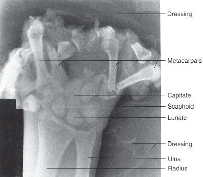
FIGURE 6.26. Left-hand AP radiograph. Obvious severe hand injuries secondary to a corn-picking accident. The phalanges are essentially missing and there are fractures of the metacarpals and carpals.
Upper Extremity
Fractures of the hands result from a wide variety of activities. Some fractures and injuries are so obvious that the average person could readily spot them on a radiograph (Fig. 6.26). Subtle fractures can involve any bone and are common in the phalanges of the hand (Figs. 6.27 and 6.28). Joint dislocations may occur in almost all joints, and the hand phalangeal joints are common dislocation sites, often related to sports (Fig. 6.29). Metacarpal fractures are also common, and fractures of the fifth metacarpal often result from punching a solid object (Fig. 6.30). These fractures are appropriately called boxer fractures although they clearly demonstrate an amateur status because professionals would strike using the second and third metacarpals. We will review some other frequently encountered fractures of the upper extremity.
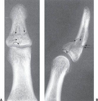
FIGURE 6.27. Left thumb PA (A) and lateral (B) radiographs. Comminuted fracture (straight arrows) that extends to the articular surface of the interphalangeal joint (curved arrow). There is mild apex palmar angulation at the fracture site (double arrows).
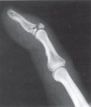
FIGURE 6.28. Right index finger lateral radiograph. Mallet finger. The distal phalanx demonstrates a slightly flexed attitude due to fracture (arrow) at site of the insertion of the extensor digitorum mechanism. The loss of the extensor mechanism continuity with the distal phalanx allows the distal phalanx to assume a flexed position or a mallet finger.
The most commonly fractured carpal is the scaphoid (Fig. 6.31). The carpal scaphoid is occasionally referred to as the navicular (an archaic term) by clinicians, but it is correctly termed the scaphoid. “Scaphoid” avoids confusion with the tarsal navicular in the foot. Scaphoid fractures result from the injury lines of force being transmitted along the long axis of the thumb, and the majority of these fractures are located in the scaphoid waist. Because of the location of its blood supply and variable arterial branches, scaphoid fractures may develop complications such as nonunion and AVN, which may result in secondary development of arthritis. These complications are more apt to occur when there is delayed diagnosis and delayed or inadequate treatment. If a scaphoid fracture is suspected but the initial radiographs are negative, additional radiography, CT, or MRI is indicated if casting and repeat radiograph in 1 week is not practical (Fig. 6.32).
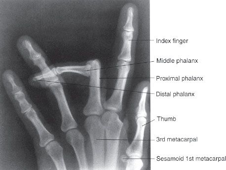
FIGURE 6.29. Left-hand PA radiograph. Dislocation at the proximal interphalangeal (PIP) joint of the left long finger. The middle and distal phalanges are completely dislocated relative to the proximal phalanx. There are no fractures.
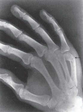
FIGURE 6.30. Right-hand PA oblique radiograph. Boxer or Saturday night fracture. The apex dorsal angulated fracture (arrow) is through the neck of the right fifth metacarpal.
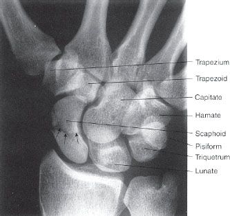
FIGURE 6.31. Right wrist PA radiograph. Essentially nondisplaced fracture (arrows) of the scaphoid waist.
Using arms and outstretched hands to cushion falls often results in fractures about the wrist. Whereas young adults typically fracture the scaphoid, children and older adults are more likely to fracture the distal radius and ulna. One such common fracture is called the Colles fracture (Fig. 6.33). It is imperative to reduce these fractured bones as close to their normal anatomic alignment as possible. Anything less than anatomic realignment may result in a painful and/or poorly functioning wrist. Therefore, it is important to know that the radial styloid tip is 1 to 1.5 cm distal to the ulnar styloid tip and the distal radial articular surface slopes 15 to 25 degrees toward the ulna and 10 to 25 degrees volar or anteriorly. Anatomic reduction may not be necessary in the nondominant hand of a person, where “less than anatomic” may still lead to a functional outcome. Children, of course, have a remarkable ability to remodel and anatomic realignment is not usually needed, depending on the age of the child. In fact, to avoid future limb length discrepancy, anatomic realignment may be purposely avoided.
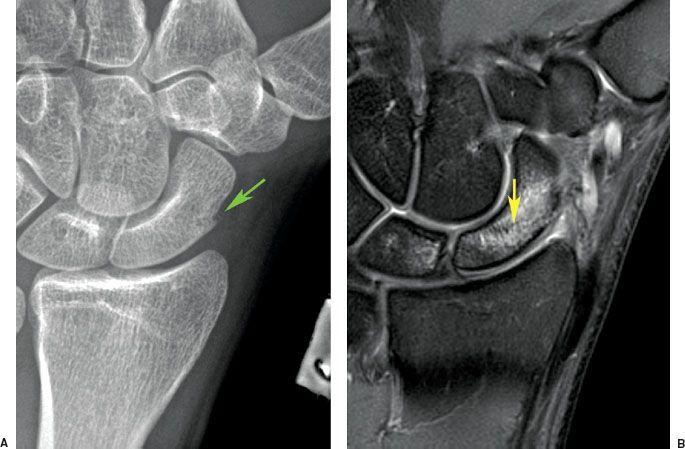
FIGURE 6.32. A: PA oblique radiograph of the scaphoid. A prominent scaphoid tubercle is seen (arrow) and obliteration of normal fat next to the bone, but no definite fracture is seen. B: Fat-suppressed T2-weighted MR image of the scaphoid reveals edema and a fracture line (arrow), which does not extend through the medial margin consistent with an incomplete fracture.
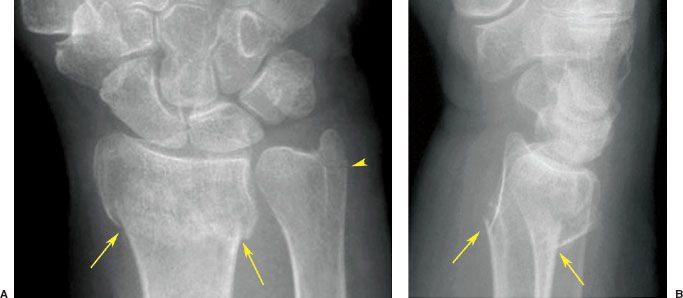
FIGURE 6.33. Right wrist PA (A) and lateral (B) radiographs. Colles fracture. There are fractures of the distal radius (arrows) and the ulna styloid (arrowhead) with dorsal tilting of the distal radius fracture fragment. The pronator fat stripe is obliterated when compared with Figure 6.1B. The ulna styloid is not displaced. Note that the radius is slightly impacted with its articular surface proximal to the ulnar head. Reduction will try to bring to neutral or restore the volar (anterior) tilt.
A subtle fracture in the distal forearm of children is the torus fracture (Fig. 6.34). As mentioned previously, torus does not refer to a bull but rather the convex molding/projection (torus) located at the base of a classical column. The torus fracture on a radiograph usually appears as a minimal bump on the bone without a visible fracture line. It represents a buckling of the bone cortex since a child’s bones are more elastic and able to bend. On occasion, the force may create an incomplete or greenstick fracture (Fig. 6.35A, B), so named because a “green” or freshly cut stick will not break through and through when bent as a dried one will. However, most fractures of the radius and ulna that are encountered in practice are much more obvious (Fig. 6.35C–E).
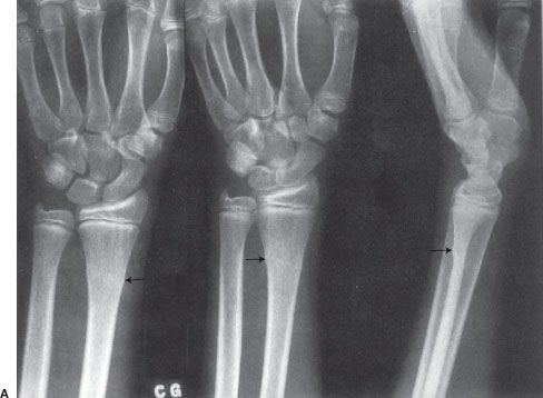
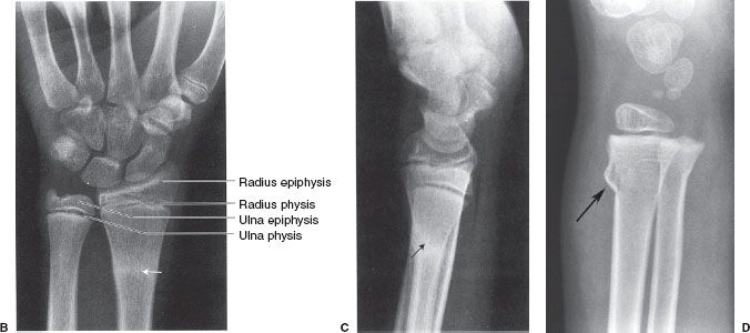
FIGURE 6.34. A: Left wrist PA, oblique, and lateral radiographs. Torus fracture (arrows) or a nondisplaced fracture of the distal left radius. Left wrist PA (B) and lateral (C) radiographs. Healing left radius torus fracture 6 weeks following the radiograph shown in A. The dense white zone (arrows) is the typical appearance of a healing fracture. D: Right wrist lateral radiograph in a younger child demonstrates a more obvious torus fracture (arrow).

FIGURE 6.35. A: AP view of the right clavicle shows a greenstick fracture of the superior cortex of the clavicle (arrow ). Note the open physis of the humerus indicating the young age of the patient. Right forearm AP (B) and lateral (C) radiographs. Complete transverse fractures (arrows) of the distal shafts of the radius and ulna in a 15-year-old. There is mild apex volar, or apex anterior, angulation at the radius fracture site. The fracture fragments in the ulna are mildly offset. D: Right forearm AP radiograph. Healing fractures (straight arrows) of the radius and ulna in a young child. The fractures are remodeling to near-anatomic alignment and the curved arrows indicate periosteal reaction and new bone formation. The fracture lines are not visible, suggesting early bone union.
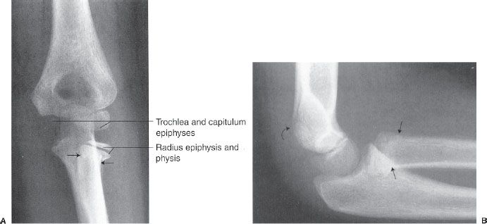
FIGURE 6.36. Left elbow AP (A) and lateral (B) radiographs. Radial neck fracture. The straight arrows indicate the site of the fracture and the radial head is tilted laterally on the AP view. The fracture is very difficult to see on the lateral view (straight arrows). A positive fat pad sign is faintly visible posterior to the distal humerus (curved arrow) on the lateral view and this always means that one should carefully evaluate for a fracture. A visible fat pad anterior to the distal humerus is normal so long as it is not overly prominent (see Fig. 6.4).
Related posts:
Stay updated, free articles. Join our Telegram channel

Full access? Get Clinical Tree


