Fig. 1
The MRIVIEW 2D interface, shown here after performing a segmentation of MRI head data into 6 tissue types
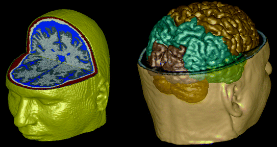
Fig. 2
The 6 tissue class segmentation is shown in 3D on the left. A segmentation of the major brain compartments is rendered in 3D on the right
4 Constrained 3D Interface
In order to localize MEG-derived brain activity on brain anatomy, it is often necessary to identify head fiducials in the MRI head data volume. The Con- strained 3D Interface was initially developed to address this problem. With it, a user can obtain five head surface views (front, back, top, and sides), by selecting an isosurface value. A data structure links these five views to location information, so that cursoring over any of the five surfaces will select the corresponding orthogonal slice views, also shown in the interface (see Fig. 3). After the user selects fiducials corresponding to those used when obtaining MEG (or EEG) data, an MEG- (or EEG)-to-MRI coordinate transformation can be obtained, and used both for MEG (or EEG) forward (and thus inverse) calculations, and to plot representations of source activity on the MRI-based brain anatomy.
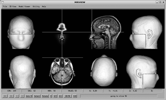

Fig. 3
The 8-panel view of the constrained 3D interface, showing selection of the nasion
The other major use of the Constrained 3D Interface is with the MEG/EEG For- ward Simulator. This will be discussed in the Forward Simulator section below.
5 Full 3D Interface
A full 3D interface, called the Model Viewer, was developed to show combinations of MRI-derived anatomy with representation of brain activity and sensor locations in a full 3D viewing environment. The Model Viewer consists of a procedural-based graphical user interface (GUI) that makes calls to an object-oriented viewing engine, which in turn utilizes many of the capabilities in the IDL Object Graphics library. The Model Viewer provides four model objects, that are used to store either volumetric or geometric data. Typically, the MRI data is loaded into Model 1, while source representations and other geometric information is loaded into Models 2 through 4. An isosurface of the MRI data can be obtained, and sliced in the 3 orthogonal directions to provide 3D reference anatomy. The slices and isosurface can each be shaded and colored independently, and are all stored in a single viewer model (Fig. 4). The Model Viewer can be used to show combinations of anatomy, sensor locations and magnetic or electric field values by using the available model containers to independently control, then combine model elements, as shown in Fig. 5.
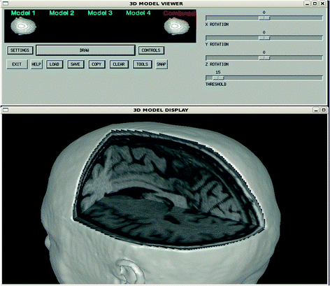
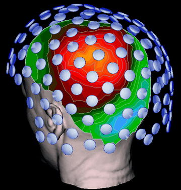

Fig. 4
3D model viewer user interface (above) and display window (below) showing orthogonal cutplanes

Fig. 5
MRI-based head anatomy is combined with MEG sensor geometry, and a color contour map representation of the magnetic field at the head surface
The 3D Model Viewer has a small set of application programming interface (API) routines that can be used to perform more generalized 3D model viewing, including movie generation. The image in Fig. 6 is one frame from a neuron activation simulation movie, showing the changing electric potentials within the neuron, and corresponding magnetic fields surrounding it (Blagoev et al. 2007).
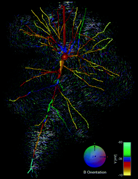

Fig. 6
A frame from a neuron electric potential and magnetic field simulation, generated using the API capabilities of the model viewer
6 MEG/EEG Inverse Modeling
Inverse modeling is integrated into the Model Viewer interface of MRIVIEW, using CSST. In CSST, a multi-dipole inverse procedure is started M times, using M sets of N randomly chosen locations. M and N are user inputs, with N being the dipole model order. In CSST, the cortical voxel locations obtained with the segmentation procedures in the 2D Interface provide the set of locations from which the random starting points are selected. The segmentation procedures can be used to select different types of starting location sets, such as all the brain voxel locations, or locations from a selected area of the brain. Originally, cortical locations were typically used, because they provide good coverage of the brain using less than 40,000 points. Currently, the preferred approach uses a calibrated grid that spans the entire brain, with the grid becoming coarser for deeper regions of the brain, since brain activity in these deeper regions cannot be localized as accurately as more superficial sources, based on Cramer-Rao bounds (Mosher et al. 1993). Figure 7 shows a typical grid of starting locations. For each set of starting locations, the multi-dipole procedure implemented in CSST uses the Nelder-Mead nonlinear simplex procedure (Nelder and Mead 1965) to perform a spatial search. For each step of the simplex search, a singular value decomposition is used to obtain a linear fit to the sensor measurements, using a spherical model for MEG or a 3 sphere model for EEG, with unconstrained dipole orientations. A reduced Chi square value is calculated for this fit. This is the value that is minimized by the simplex procedure. The user selects how many of the best fits to save for a given program run. After processing, the Model Viewer in MRIVIEW can be used to display the CSST results (see Fig. 8).
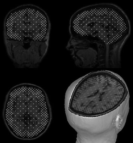
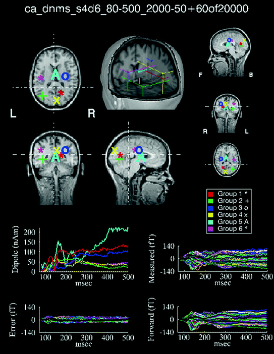

Fig. 7
Grid of brain locations from which CSST randomly selects numerous sets of initial dipole locations

Fig. 8
CSST results for an MEG visual study, showing the best 60, 6-dipole fits from 20,000 starts
For higher-dipole model orders (e.g., 5–9 dipoles) multi-start procedures become computationally intensive. For this reason, CSST, written in IDL, has been parallelized using the Message Passing Interface (MPI). The parallel version, MPI_CSST, uses a C language implementation of MPI to distribute the multiple starts across a user-selected number of processors in a Linux cluster, each running an instance of CSST. Each instance of CSST runs with its subset of the original set of starting locations. As each CSST process completes, the output is collated with the output from CSST processes that have already completed, to produce a combined output with the number of best fits requested by the user. The performance of MPI_CSST scales linearly with the number of processors used. The speed-up obtained using multiple processors makes the real-time use of MPI_CSST feasible.
6.1 Two-Stage Simplex Search
Many starting dipole configurations are far removed from an optimal solution, and end up converging on sub-optimal solutions after many iterations of the simplex minimization procedure. For this reason, a two-stage simplex approach has been added to MPI_CSST. Stage one uses a coarse convergence setting in the simplex procedure, saving a user-selected number of best solutions. A fine convergence setting is used in the second stage on these best solutions, to obtain the final results. This two-stage approach reduces the analysis time by 50 % or more, compared to the single-stage approach.
6.2 MUSIC-Seeded CSST
Stay updated, free articles. Join our Telegram channel

Full access? Get Clinical Tree


