A System of Dosimetric Calculations
Several methods are available for calculating absorbed dose in a patient. Two of these methods using percent depth doses and tissue-air ratios (TARs) were discussed in Chapter 9. However, there are some limitations to these methods. For example, the dependence of percent depth dose on source to surface distance (SSD) makes this quantity unsuitable for isocentric techniques. Although tissue-air ratios (TARs) and scatter-air ratios (SARs) eliminate that problem, their application to beams of energy higher than those of 60Co has been seriously questioned (1,2,3) as they require measurement of dose in free space. As the beam energy increases, the size of the chamber buildup cap for in-air measurements has to be increased and it becomes increasingly difficult to calculate the dose in free space from such measurements. In addition, the material of the buildup cap is usually different from that of the phantom and this introduces a bias or uncertainty in the TAR measurements.
In order to overcome the limitations of the TAR, Karzmark et al. (1) introduced the concept of tissue-phantom ratio (TPR). This quantity retains the properties of the TAR but limits the measurements to the phantom rather than in air. A few years later, Holt et al. (4) introduced yet another quantity, tissue-maximum ratio (TMR), which also limits the measurements to the phantom.
In this chapter, I develop a dosimetric system based on the TMR concept, although a similar system can also be derived from the TPR concept (5).
10.1. Dose Calculation Parameters
The dose to a point in a medium may be analyzed into primary and scattered components. The primary dose is contributed by the initial or original photons emitted from the source and the scattered dose is the result of the scattered photons. The scattered dose can be further analyzed into collimator and phantom components, because the two can be varied independently by blocking. For example, blocking a portion of the field does not significantly change the output or exposure in the open portion of the beam (6,7) but may substantially reduce the phantom scatter. The above analysis presents one practical difficulty, namely the determination of primary dose in a phantom that excludes both the collimator and phantom scatter. However, for megavoltage photon beams, it is reasonably accurate to consider collimator scatter as part of the primary beam so that the phantom scatter could be calculated separately. Therefore, we define an effective primary dose as the dose due to the primary photons as well as those scattered from the collimating system. The effective primary in a phantom may be thought of as the dose at depth minus the phantom scatter. Alternatively, the effective primary dose may be defined as the depth dose expected in the field when scattering volume is reduced to zero while keeping the collimator opening constant.
Representation of primary dose by the dose in a 0 × 0 field poses conceptual problems because of the lack of lateral electronic equilibrium in narrow fields in megavoltage photon beams. This issue has been debated in the literature (8,9,10), but practical solutions are still not agreed on. Systems that use electron transport in the calculation of primary and scattered components of dose would be appropriate but are not as yet fully developed and implemented. Until then, the concept of a 0 × 0 field to represent primary beams with the implicit assumption that lateral electronic equilibrium exists at all points will continue to be used for routine dosimetry.
Notwithstanding the weakness of the above assumption, the depth dose distribution for a 0 × 0 field, in practice, is obtained by extrapolation. The data for small fields, down to a size just enough
to provide lateral electronic equilibrium (e.g., 3 × 3 to 5 × 5 cm for most energies), are extrapolated to 0 × 0 field size.
to provide lateral electronic equilibrium (e.g., 3 × 3 to 5 × 5 cm for most energies), are extrapolated to 0 × 0 field size.
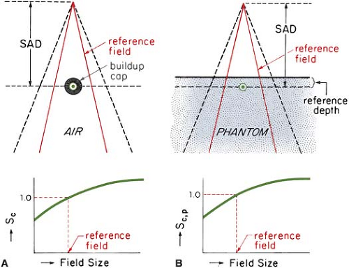 Figure 10.1. Arrangement for measuring Sc and Sc,p. A: Chamber with buildup cap in air to measure output relative to a reference field, for determining Sc versus field size. B: Measurements in a phantom at a fixed reference depth for determining Sc,p versus field size. SAD, source to axis distance. (From Khan FM, Sewchand W, Lee J, et al. Revision of tissue-maximum ratio and scatter-maximum ratio concepts for cobalt 60 and higher energy x-ray beams. Med Phys. 1980;7:230, with permission.) |
A. Collimator Scatter Factor
The beam output (exposure rate, dose rate in free space, or energy fluence rate) measured in air depends on the field size. As the field size is increased, the output increases because of the increased collimator scatter,1 which is added to the primary beam.
The collimator scatter factor (Sc) is commonly called the output factor and may be defined as the ratio of the output in air for a given field to that for a reference field (e.g., 10 × 10 cm). Sc may be measured with an ion chamber with a buildup cap of a size large enough to provide maximum dose buildup for the given energy beam. The measurement setup is shown in Figure 10.1A. Readings are plotted against field size (side of equivalent square or area/perimeter [A/P]) and the values are normalized to the reference field (10 × 10 cm).
In the measurement of Sc, the field must fully cover the buildup cap for all field sizes if measurements are to reflect relative photon fluences. For small fields, one may take the measurements at large distances from the source so that the smallest field covers the buildup cap. Normally, the collimator scatter factors are measured at the source to axis distance (SAD). However, larger distances can be used provided the field sizes are all defined at the SAD.
B. Phantom Scatter Factor
The phantom scatter factor (Sp) takes into account the change in scatter radiation originating in the phantom at a reference depth as the field size is changed. Sp may be defined as the ratio of the dose rate for a given field at a reference depth (e.g., depth of maximum dose) to the dose rate at the same depth for the reference field size (e.g., 10 × 10 cm), with the same collimator opening. In this definition, it should be noted that Sp is related to the changes in the volume of the phantom irradiated for a fixed collimator opening. Thus, one could determine Sp, at least in concept, by using a large field incident on phantoms of various cross-sectional sizes.
For photon beams for which backscatter factors can be accurately measured (e.g., up to cobalt-60), Sp factor at the depth of maximum dose may be defined simply as the ratio of backscatter factor (BSF) for the given field to that for the reference field (see Appendix, section A). Mathematically:
where r0 is the side of the reference field size (10 × 10 cm).
A more practical method of measuring Sp, which can be used for all beam energies, consists of indirect determination from the following equation (for derivation, see Appendix, section A):
where Sc,p(r) is the total scatter factor defined as the dose rate at a reference depth for a given field size r divided by the dose rate at the same point and depth for the reference field size (10 × 10 cm) (Fig. 10.1B). Thus, Sc,p(r) contains both the collimator and phantom scatter and when divided by Sc(r) yields Sp(r).
Since Sp and Sc,p are defined at the reference depth of Dmax, actual measurement of these factors at this depth may create problems because of the possible influence of contaminant electrons incident on the phantom. This can be avoided by making measurements at a greater depth (e.g., 10 cm) and converting the readings to the reference depth of Dmax by using percent depth dose data, presumably measured with a small-diameter chamber. The rationale for this procedure is the same as for the recommended depths of calibration (11).
C. Tissue-Phantom and Tissue-Maximum Ratios
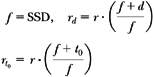
The TPR is defined as the ratio of the dose at a given point in phantom to the dose at the same point at a fixed reference depth, usually 5 cm. This is illustrated in Figure 10.2. The corresponding quantity for the scattered dose calculation is called the scatter-phantom ratio (SPR), which is analogous in use to the scatter-air ratio discussed in the previous chapter. Details of the TPR and SPR concepts have been discussed in the literature (1,3,5).
TPR is a general function that may be normalized to any reference depth. But there is no general agreement concerning the depth to be used for this quantity, although a 5-cm depth is the usual choice for most beam energies. On the other hand, the point of central axis Dmax has a simplicity that is very desirable in dose computations. If adopted as a fixed reference depth, the quantity TPR gives rise to the TMR. Thus, TMR is a special case of TPR and may be defined as the ratio of the dose at a given point in phantom to the dose at the same point at the reference depth of maximum dose (Fig. 10.2).
For megavoltage beams in the range of 20 to 45 MV, the depth of maximum dose (dm) has been found to depend significantly on field size (12,13) as well as on SSD (14,15). For the calculative functions to be independent of machine parameters, they should not involve measurements in the buildup region. Therefore, the reference depth must be equal to or greater than the largest dm. Since dm tends to decrease with field size (12) and increase with SSD (14), one should choose (dm) for the smallest field and the largest SSD. In practice, one may plot [(%DD) × (SSD + d)2] as a function of depth d to find dm (15). This eliminates dependence on SSD. The maximum dm can then be obtained by plotting dm as a function of field size and extrapolating to 0 × 0 field size.
The reference depth of maximum dose (t0), as determined above, should be used for percent depth dose, TMR, and Sp factors, irrespective of field size and SSD.
C.1. Properties of TMR
The concept of tissue-maximum ratio is based on the assumption that the fractional scatter contribution to the depth dose at a point is independent of the divergence of the beam and depends only on the field size at the point and the depth of the overlying tissue. This has been shown to be essentially true by Johns et al. (16). This principle, which also underlies TAR and TPR, makes all these functions practically independent of source to surface distance. Thus, a single table of TMRs can be used for all SSDs for each radiation quality.
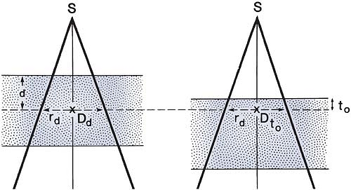 Figure 10.2. Diagram illustrating the definitions of tissue-phantom ratio (TPR) and tissue-maximum ratio (TMR). TPR(d, rd) = Dd/Dt0, where t0 is a reference depth. If t0 is the reference depth of maximum dose, then TMR(d, rd) = TPR(d, rd). |
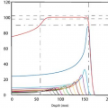
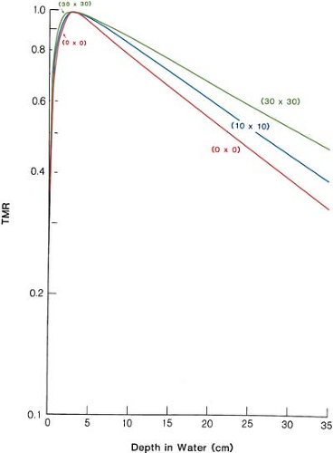 Figure 10.3. Plot of tissue- maximum ratio (TMR) for 10-MV x-rays as a function of depth for a selection of field sizes. |
Figure 10.3 shows TMR data for 10-MV x-ray beams as an example. The curve for 0 × 0 field size shows the steepest drop with depth and is caused entirely by the primary beam. For megavoltage beams, the primary beam attenuation can be approximately represented by:
where μ is the effective linear attenuation coefficient and t0 is the reference depth of maximum dose. μ can be determined from TMR data by plotting μ as a function of field size (side of equivalent square) and extrapolating it back to 0 × 0 field.
TMR and percent depth dose P are interrelated by the following equation (see Appendix, section B, for derivation):
where
Here the percent depth dose is referenced against the dose at depth t0 so that P(t0, r, f) = 100 for all field sizes and SSDs.
Although TMRs can be measured directly, they can also be calculated from percent depth doses, as shown by Equation 10.4. For 60Co, Equations 10.2 and 10.4 can be used to calculate TMRs. In addition, TMRs can be derived from TAR data in those cases, such as 60Co, where TARs are accurately known:
D. Scatter-Maximum Ratio
The scatter-maximum ratio (SMR), like the SAR, is a quantity designed specifically for the calculation of scattered dose in a medium. It may be defined as the ratio of the scattered dose at a given point in phantom to the effective primary dose at the same point at the reference depth of maximum dose (5). Mathematically:
For derivation of the above equation, see Appendix, section C.
From Equations 10.1, 10.5, and 10.6, it can be shown that for 60Co γ rays, SMRs are approximately the same as SARs. However, for higher energies, SMRs should be calculated from TMRs by using Equations 9.7 and 10.6.
Another interesting relationship can be obtained at the reference depth of maximum dose (t0). Since TMR at depth t0 is unity by definition, Equation 10.6 becomes:
This equation will be used in section 10.2C.
10.2. Practical Applications
Radiotherapy institutions vary in their treatment techniques and calibration practices. For example, some rely exclusively on the SSD- or the SAD (isocentric)-type techniques, while others use both. Accordingly, units are calibrated in air or in phantom at a suitable reference depth. In addition, clinical fields, although basically rectangular or square, are often shaped irregularly to protect critical or normal regions of the body. Thus, a calculation system must be generally applicable to the above practices, with acceptable accuracy and simplicity for routine use.
A. Accelerator Calculations
A.1. SSD Technique
Percent depth dose is a suitable quantity for calculations involving SSD techniques. Machines are usually calibrated to deliver 1 rad (10-2 Gy) per monitor unit (MU) at the reference depth t0, for a reference field size 10 × 10 cm and a source to calibration point distance of SCD. Assuming that the Sc factors relate to collimator field sizes defined at the SAD, the monitor units necessary to deliver a certain tumor dose (TD) at depth d for a field size r at the surface at any SSD are given by:
where K is 1 rad per MU, rc is the collimator field size, given by:
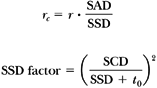
and:
It must be remembered that, whereas the field size for the Sc is defined at the SAD, Sp relates to the field irradiating the patient.
Related posts:

Stay updated, free articles. Join our Telegram channel

Full access? Get Clinical Tree


