Term
Definition
Medical global positioning system (GPS)
Localization of a device or image in relation to prior pre-procedural imaging. The electromagnetic field generator is the “satellite” and the needle tip is the “car”
Multimodality or image fusion
Overlapping visual display of multiple imaging modalities during a percutaneous biopsy
Electromagnetic tracking
Mechanism to locate a needle (or ultrasound plane) within a 3D volume of imaging data (like CT, MR, or PET) or to locate a 2D ultrasound plane within a 3D volume
Tracking error/target to registration Error (TRE)
Difference between the real and virtual needle positions. How accurate is the location of the “virtual needle” as displayed on the images?
Registration error (root mean square/RMS)
How well two sets of imaging data or selected anatomic points on each of two imaging modalities match up (ideally <2 mm)
Placement error
How close the needle is placed to the target point
Dynamic reference
Patch or sensor placed on patient that corrects for patient or generator motion. Without this, patient must remain in exact position throughout body intervention
Registration
Matches two (or more) sets of imaging data, or matches image space to “magnetic space”
Rigid registration
Matches two (or more) sets of imaging data based upon fixed anatomic landmarks; it does not, on its own, account for organ shift or tissue deformation between image sets or during the procedure
Deformable/elastic registration
Matches two (or more) sets of imaging data based upon common anatomic landmarks but can deform/warp image sets to account for organ shift or deformation between different images or due to imaging at different times
Medical robot
Mechanical manipulator connected by joints that allow relative motion from one link to another
Robotic arm
Part of the robot that orients the end effectors and/or sensors
End effector
Any attachment on the end of a robot that interacts with the environment, such as a device to lift and position a needle; the robotic “hand” at the end of the robot arm
Degrees of freedom
Axes of movement; reflect the flexibility of an instrument (robot) to achieve positions and orientations. Six degrees of freedom are required for a robotic device to reach, position, and orient an instrument at any point in space. The seventh degree of freedom is inherent to the procedure itself (e.g., cutting, grasping)
Device Tracking
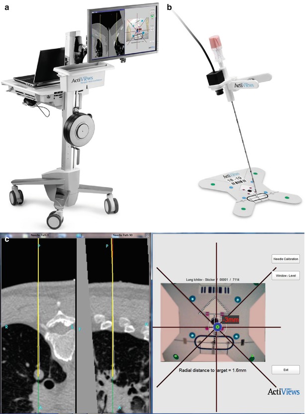
The primary methods for real-time device tracking include electromagnetic tracking and optical tracking. Electromagnetic (EM) and optical tracking are standard techniques used to register devices to preoperative images during neurosurgery and orthopedic surgery, but these technologies have not been widely applied in interventional radiology [3]. Medical devices like needles, catheters, and guidewires may be tracked via placement of minute electromagnetic sensor coils within their tips (PercuNav Image Fusion and Instrument Navigation, Philips Healthcare, Cleveland, Ohio). Tracking of these sensor coils provides spatial information on internal device location in real time during a biopsy, relative to preoperative imaging anatomy (CT, MR, PET). This tracking is analogous to a miniaturized global positioning system (GPS) [3, 9]. The minute size of EM sensor coils allows localization and tracking of internalized medical devices; at present, these can be fitted within coaxial biopsy introducers, stylets, and hollow cannulas as small in diameter as 22 gauge [3]. Optical and infrared tracking of devices requires either optical or infrared cameras, which require direct line of sight that is less practical in the setting of image-guided biopsy [9]. Electromagnetic tracking requires a small EM field generator and software to detect and display the tracked devices (Fig. 7.1). Registration between tracking space and image space may be performed by using reference markers attached to the skin near the planned needle entry point (“fiducials”). These may be either passive fiducial markers or actively tracked fiducials (or patches) with sensors integrated directly inside the fiducial. After identifying the fiducials on intra-procedural CT, the corresponding tracking coordinates may be obtained automatically (or alternatively by pointing the tracked needle to each of the fiducials during the breath hold and averaging the tracking signal for several seconds until a stable reading is obtained). A rigid registration transformation between tracking coordinates and CT image coordinates is computed, and the root-mean-square distance (fiducial registration error) between the CT image coordinates of the fiducials and the transformed tracking coordinates of the fiducials is displayed. The registration with the lowest fiducial registration error is used, typically with a fiducial registration error (FRE) smaller than 2 mm. Sensor coil placement upon an ultrasound probe can also enable tracking of the US transducer. Correction for the moving liver may be attempted with tracking of the hepatic biopsy needle itself or other gating methods. The interventional radiologist is essentially provided with a road map to facilitate needle placement and repositioning, by having information about biopsy needle location, referenced within pre-procedural imaging. Use of this technology has the potential to be superior to the use of conventional biopsy technique, particularly for lesions whose intra-procedural visualization is suboptimal relative to pre-acquired images, e.g., tumors that are only briefly seen during arterial-phase CT (Fig. 7.2).
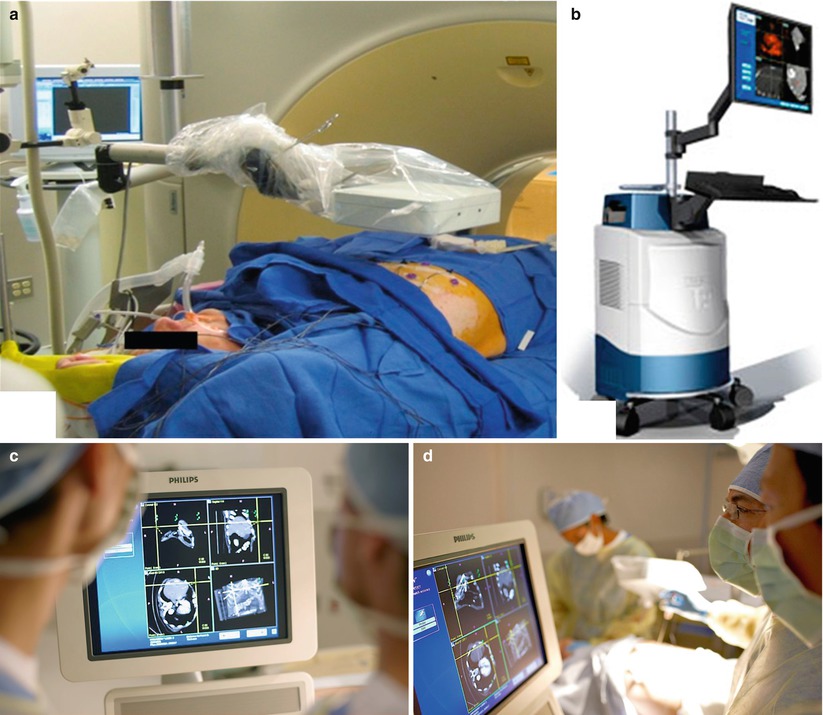
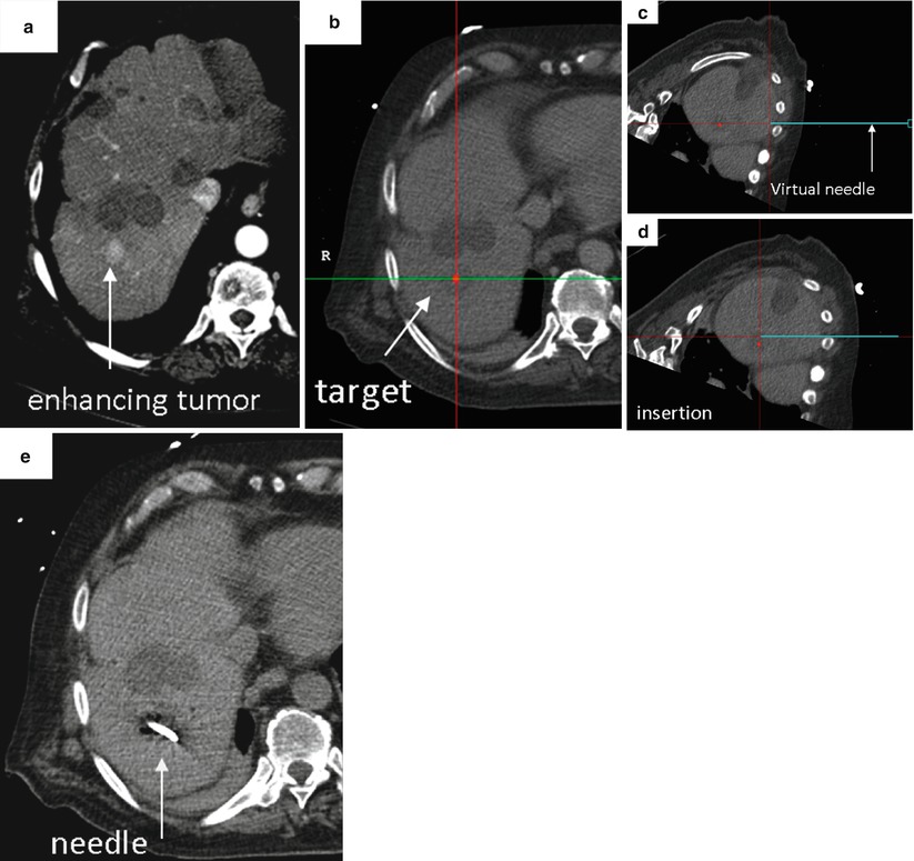
Fig. 7.1
Components for electromagnetic needle tracking during percutaneous biopsy. (a) An electromagnetic field generator, sterilely draped, is placed near the working space, directed toward the target and path of needle entry to facilitate image co-registration and device tracking. (b) Navigation workstation that enables display of co-registered images and tracked needle during biopsy (PercuNav Image Fusion and Instrument Navigation, Philips Healthcare, Cleveland, Ohio). (c) Custom software with display of tracked needle superimposed on multiplanar CT images co-registered to real-time ultrasound. (d) Use of needle tracking and multimodality image display facilitates percutaneous biopsy (Image a reprinted with permission from Venkatesan et al. [10], Radiological Society of North America (RSNA). Images b–d reprinted with permission from Philips Healthcare, Cleveland, Ohio)
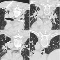
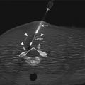
Fig. 7.2
Representative case using image fusion and needle tracking to facilitate percutaneous biopsy. (a) Pre-procedural imaging demonstrates the target, a briefly apparent 1 cm arterially enhancing lesion that was not well seen on non-contrast CT, venous phase CT or ultrasound. (b) Intra-procedural CT with selected location of target highlighted as a red dot on the navigation workstation. The location and orientation of the tracked needle is displayed as a blue “virtual needle.” (c and d) Serial images demonstrate location and position of tracked needle relative to target during needle insertion. (e) Intra-procedural CT confirms needle tip within location of target. Percutaneous biopsy of this small (1 cm) nodule yielded a diagnosis of hepatocellular carcinoma (Reprinted with permission from Wood et al. [8])
Early clinical trials suggest good spatial accuracy and feasibility of electromagnetic needle tracking. Kruecker et al. evaluated the spatial accuracy of electromagnetic needle tracking and demonstrated the feasibility of US to CT fusion during CT- and US-guided biopsy and radiofrequency ablation (RFA) procedures, performing a 20-patient clinical trial to investigate electromagnetic needle tracking during interventional procedures [11]. Eight patients underwent RFA; the remainder underwent needle biopsy of sites in the liver, kidney, lung, chest wall, and retroperitoneum [11]. Needles were positioned by using CT and US guidance, and an electromagnetic tracking system was used consisting of internally tracked needles and software to record needle positions relative to previously obtained CT scans (Philips Healthcare, Cleveland, Ohio, formerly Traxtal, Inc., Toronto, CA and Philips Research, Briarcliff, NY) [11]. The electromagnetic field generator was mounted on an articulated mechanical arm, which was attached to a stereotactic frame connected to the CT gantry or simply mounted on a nearby structure such as the ultrasound itself or table [11]. Position tracking data were acquired to evaluate the tracking error [11]. Registration between tracking space and image space was obtained by using reference fiducial markers (or patches) attached to the skin [11]. The US transducer was tracked to demonstrate real-time US-CT fusion for imaging guidance, where the needle is displayed on the ultrasound as well as the pre-procedural CT image [11]. The basic tracking error was 3.5 mm ± 1.9 with use of nonrigid registrations that used previous internal needle positions as additional fiducials reference markers and more recently was found to be 2.7 ± 1.6 mm in a more recent 35-patient study [11, 12]. Fusion of tracked US with CT was successful; patient motion and distortion of the tracking system by the CT table and gantry were identified as sources of error [11]. The spatial tracking accuracy of this system was sufficient to display clinically relevant pre-procedural imaging information during needle-based procedures. Particular benefit was noted for virtual needles displayed within pre-procedural images of transiently apparent targets, such as arterial-phase enhancing liver lesions, or during thermal ablations when obscuring gas is released [11].
Santos et al. evaluated an electromagnetic (EM) navigation system (Veran Medical Technologies Inc, St. Louis, MO) to assess its potential to reduce the number of skin punctures and instrument adjustments during CT-guided percutaneous ablation and biopsy of small (<2 cm) lung nodules [12]. Nineteen EM interventions were performed, including 6 biopsies, 9 radiofrequency ablations (RFAs), 1 combined biopsy with an RFA, and 3 microwave ablations [12]. Median nodule diameter was 1.95 cm (range, 1.2–2.4 cm), and median distance from the skin to lesion was 7.6 cm (2–18 cm) [12]. When an EM-guided biopsy was performed, the intervention was done immediately prior to ablation. For all 19 EM interventions, only one skin puncture was required. The mean number of instrument adjustments required was 1.2 (range, 0–2) [12]. The mean time for each EM intervention was 5.2 min (range, 1–20 min) [12]. Pneumothorax occurred in five patients (50 %), with only the number of instrument adjustments being significantly related to the pneumothorax rate (p < 0.005) [12]. The authors concluded that the EM navigation is feasible and a useful aid for image-guided biopsy and ablation of small pulmonary tumors [12]. Their experience suggests the EM navigation system might require fewer skin punctures and instrument adjustments for lung biopsies than using CT fluoroscopy guidance alone [12].
The use of fusion-guided biopsy and ablation has demonstrated improvement over conventional CT and US guidance in terms of improved angle selection compared to conventional technique. Kruecker et al. reported that the addition of needle and ultrasound tracking improved needle path “off-target error” from 17.8 ± 17.1 mm to 3.3 ± 3.1 mm and changed insertion angle by 13.3° ± 6.5°. This added accuracy has the potential to translate into improved outcomes, particularly for biopsy or ablation of occult targets, where targeting accuracy is crucial [13].
A recent clinical study has evaluated this potential, by assessing the feasibility of combined electromagnetic device tracking and computed tomography (CT)/ultrasonography (US)/fluorine-18 fluorodeoxyglucose (FDG) positron-emission tomography (PET) fusion for real-time feedback during percutaneous and intraoperative biopsies and hepatic radiofrequency ablation [10]. Targets demonstrated heterogeneous FDG uptake or were not well seen or were totally inapparent at conventional imaging and were thus considered technically challenging or impossible to target using conventional imaging guidance [10]. In this study, pre-procedural FDG-PET scans were rigidly registered using a semiautomatic method to intra-procedural CT. Real-time US scans were registered through a fiducial-based method, allowing US scans to be fused with intra-procedural CT and pre-acquired FDG-PET scans. A visual display of US-CT image fusion with overlaid co-registered FDG-PET targets was used for guidance [10]. Navigation software enabled real-time biopsy needle and needle electrode navigation and feedback, employing coaxial biopsy needle introducer tips and RF ablation electrode guider needle tips containing electromagnetic sensor coils spatially tracked through an electromagnetic field generator [10]. Successful fusion of real-time US to co-registered CT and FDG-PET scans was achieved in all patients, with 31 of 36 biopsies being diagnostic and one case of RF ablation resulting in resolution of targeted FDG avidity, with no local treatment failure over a short follow-up period [10].
Additional Navigation Tools for Device Tracking
Additional tools facilitating needle tracking for percutaneous biopsy include mechanical devices, optical devices, and rotational CT-based tools. Mechanical devices include commercial needle stabilizers, which may be fixed to a patient’s skin via adhesive and which contain a central needle guide, into which a biopsy needle may be inserted, with the initial biopsy needle angle selected by the operator being able to be “locked” into position within the stabilizer, enabling maintenance of the same needle angle throughout the process of needle insertion to the desired target. Commercial devices facilitating needle angle precision include the SeeStar (St. Jude Medical, formerly Radi Medical Systems, St. Paul, MI) and the Simplify (NeoRad, Oslo, Norway) (Fig. 7.3).
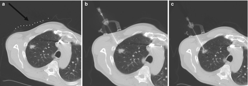
Fig. 7.3
Representative images during percutaneous lung biopsy using the Simplify (NeoRad, Oslo, Norway). (a) Grid placement and initial CT scan confirms right upper lobe lung nodule for biopsy. A grid is placed on the overlying skin to mark the target at the level of the skin (black arrow). (b) Simplify placed on the skin enables maintenance of initial needle angle throughout needle insertion. (c) Successful percutaneous needle biopsy of the targeted lesion
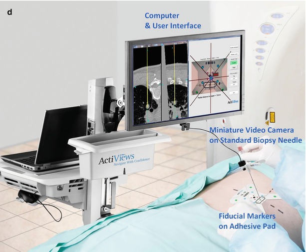
Optical tracking devices for percutaneous biopsy involve optical sensors which may be mounted on needles or probes that may be paired with custom software enabling multiplanar display of patient anatomy, including the location of the desired target in relation to the needle during needle insertion, thereby potentially minimizing the number of serial CT scans required to perform a biopsy, reducing procedure time and radiation dose. The CT-Guide® optical guidance system (approved for marketing in USA, China, Europe, Canada, and Israel) is one example of an optical guidance system for use in CT-guided needle procedures (ActiViews Ltd., Haifa, Israel). Components of this system include a disposable, miniature video camera that may be mounted on any commercial needle or probe, fiducial markers printed on a flexible adhesive pad, and a custom computer graphical user interface. The pre-procedural CT images with overlying fiducial markers are imported into the custom planning software and used for target and angle selection and real-time guidance (see Fig. 7.4).