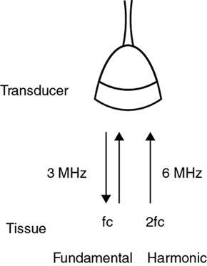
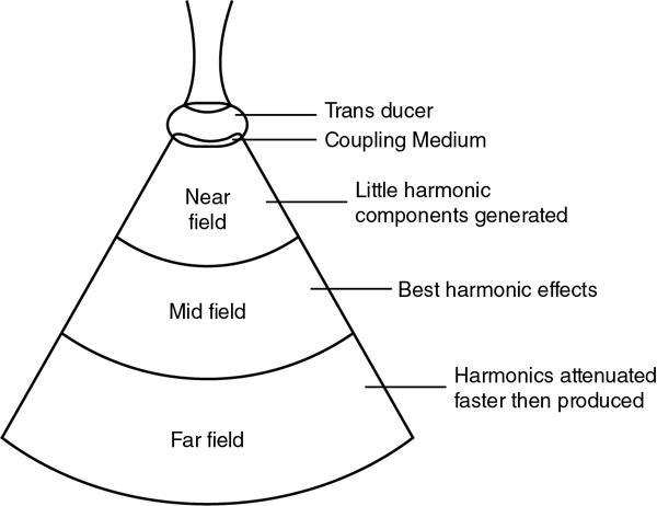
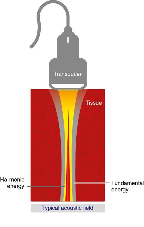
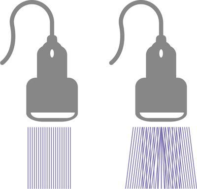
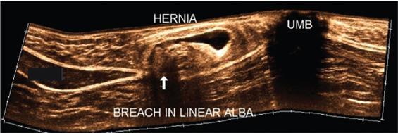
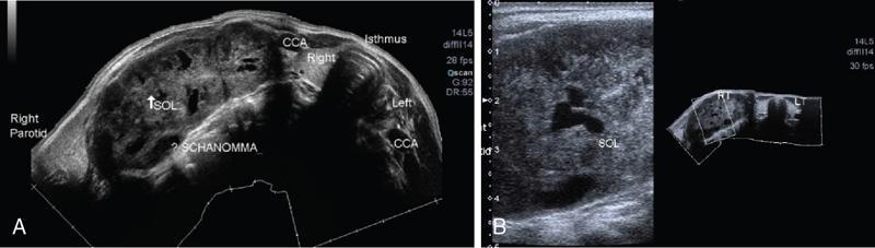
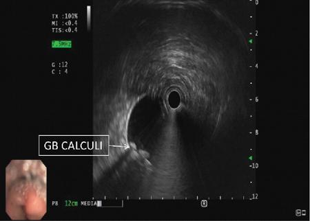
Alka Ashmita Singhal Any sufficiently advanced technology is indistinguishable from magic. Arthur C Clarke Technological advances in the field of ultrasound have been evolving rapidly, and it is prudent to keep pace with the evolving applications and to effectively utilize them to maximize diagnostic performance and improve patient outcomes. This chapter aims to introduce some of the advancements in ultrasound. Tissue harmonic imaging (THI) is a B mode imaging technique that improves ultrasound image quality by reducing superficial artefact. It increases the image signal-to-noise ratio whilst reducing axial resolution. It is also called native harmonic imaging as the harmonics here originate from the native tissues. These were discovered accidently in the year 1996 by Burns during research on contrast bubbles and are related to the resonance of the tissues in response to ultrasound pulses. Conventional ultrasound involves the propagation of longitudinal sound waves composed of alternating zones of compression and rarefaction to travel through an elastic medium or a tissue. When a sound wave passes through an elastic medium, the higher density compression phase travels faster than the lower density rarefaction phase leading to nonlinear harmonic distortion of the original pure fundamental frequency. This harmonic distortion is cumulative and produces a stronger harmonic component with a higher amplitude wave. Harmonic components are multiples of fundamental frequency. For example, in case of a 3 MHz transducer which has fundamental frequency centred at 3 MHz, tissue harmonic waves produced have a centring frequency of its multiples, meaning 6 MHz, 9 MHz, 12 MHz and so on (Fig. 1.22.1). The amplitudes of the harmonic waves are almost always lower than that of fundamental frequency waves. Harmonics are generated by the tissues and increase with depth to a point of maximum intensity and then decrease with further depth due to attenuation (Fig. 1.22.2). The second harmonic which is twice the fundamental frequency contains most of the harmonic energy and is the one being utilized in most ultrasound equipment for THI. Harmonics are most prominent in the central part of the transmitted beam and have maximum intensity at an optimal depth below the surface (Fig. 1.22.3). The harmonics are of higher frequency than the fundamental frequency. As they are generated within the tissues, they are less affected by the reverberation artefacts generated from the superficial fat, muscle and other layers. The harmonic waves have only to travel one way, which is towards the transducer. Various techniques such as frequency filtering, pulse inversion or phase cancellation and coded harmonics are used to process to received signal so that the echoes of harmonic frequency are used for image formation. Axial resolution is improved due to higher frequencies. The combined effects of high frequency and only one-way travel lead to the advantages of reduced reverberation, reduced beam aberration and reduced side lobes, thus helping in clearing the echoes from the cysts. Lateral resolution is improved due to narrower beam width. Decreased side lobes lead to noise reduction and improve signal to noise ratio and reduces artefacts. THI is especially valuable in diagnosing a cyst as a cyst and delineating associated echogenic tissues as calculi, fat or air shadowing. THI helps in clearing the echoes from hypoechoic and anechoic cysts, lumen of gall bladder and of large blood vessels such as IVC, aorta and carotid vessels. Its greatest applications are to solve the diagnostic dilemma in all these fluids filled structures especially when there are significant reverberation artefacts from superficial layers. THI enhances visualization of biliary ducts due to improvement in contrast resolution and reduction of side lobe artefacts. THI enhances the actual detection of an intraluminal mass or calculus in the biliary tree and the recognition of the acoustic shadow behind a calculus. THI improves conspicuity of the comet tail artefact diagnostic of adenomyomatosis of gall bladder and of thyroid colloid nodules. THI helps in improving the image resolution in patients with large body habitus (BMI >30). THI improves detection of tiny focal pancreatic abnormalities. THI improves detection and characterization of focal breast lesions by improving conspicuity of lesion, lesion border and content definition and acoustic shadow conspicuity. Improvisation in lesion detection capabilities with THI is especially valuable in fatty breasts. THI has better diagnostic accuracy for axillary lymph node evaluation. As harmonic imaging is due to higher frequency waves, the main limitation is penetration into deeper tissues. Higher frequency also leads to more shadowing and could potentially pose a dilemma in evaluation for possible calculi. The thermal and the mechanical index are the same for both harmonic and conventional imaging; hence, there is no increased exposure in harmonic imaging over conventional imaging. As against THI where half (lower half) of the available transducer bandwidth is used for image generation, DTHI makes use of the entire transducer bandwidth. This has the advantage of imaging of deeper tissues (>8 cm depth) and achieves a combination of conventional grey-scale image quality with the improved contrast resolution provided by harmonic imaging. The only requirement for DTHI is fast signal processing. DTHI uses suppression of fundamental signals by PULSE subtraction. It provides more detail resolution, greater depth penetration and higher CNR values. Dual-frequency pulse is transmitted and the received signal includes echoes, at sum and difference of frequency of the two transmitted pulses. Acoustic speckle is the undesirable random mottle pattern seen in ultrasound images caused by wave interference between unresolved scatterers. This speckle degrades the appearance of tissue texture and makes it more difficult to detect small, low contrast lesions in a tissue. In ultrasound, the difference in contrast between the two tissues may be less than even 1%. Hence, reduction in any amount of speckle leads to improved contrast resolution and better delineation of small structures having minimal or very low contrast with the background parenchyma. Compound imaging is one of the techniques used for speckle reduction. Compound imaging has the ability to acquire multiple frames simultaneously from different angles as in the case of spatial compound imaging or using different frequencies as in the case of frequency compound imaging and then these are combined to produce a multiangle or multifrequency compound image, respectively. The trade-off is slight loss of temporal and lateral resolution. Frequency compound imaging reduces the speckle by averaging two or more uncorrelated subband images. Here the bandwidth of a frequency is divided into four or more frequency subbands. Signals from those bands are then used to form subband images. These subband images are then added or averaged to produce the compound image. Various weighting factors may be applied. Since frequency division is carried out to obtain subband images containing uncorrelating speckles, it sacrifices axial resolution. Frequency compounding deteriorates the total signal to noise ratio and the target detecting capability, when the speckle’s signal to noise ratio is not improved as much as the degraded axial resolution. One solution to avoid this is to increase the effective bandwidth for frequency compounding, for example, by utilizing a dual element transducer operating at 20 and 40 MHz the effective bandwidth, arranged in concentric annular array, thus broadening the effective bandwidth for frequency compounding. Here signal to noise ratio is improved without compromise of temporal resolution and finds potential applications in cardiac imaging. Spatial compound imaging uses beam steering to quickly acquire a number of coplanar tomographic ultrasound images of an area from different view angles, and then combining them into a single compound image. Electronic bean steering is used in real time to rapidly acquire component frames (usually three to nine frames) from different angles, typically within 20° from the perpendicular. The component frames are then combined at real-time frame rates itself. The resultant compound image has advantages of reduced speckle and improved continuity of specular reflectors. As these separate coplanar images are averaged, the trade-off is reduced spatial resolution and temporal resolution. Spatial compound imaging is currently available on most ultrasound systems and has shown to improve the image quality, increase the conspicuity of low contrast lesions, lesion margins and content definition. Spatial compound imaging in breast enhances the delineation of capsular margins and ducts and improves depiction of internal architecture of solid lesions as well as clearer visualization of cystic contents due to clutter reduction. The area of greatest improvement of the image quality is seen in the central triangular area where all scan images overlap (Fig. 1.22.1) and less improvement of image quality is seen in the periphery, where fewer scan images overlap. Spatial compound sonography by reducing speckle and significantly improving the definition of tissue planes has applications in musculoskeletal sonography. Spatial compound imaging has potential applications for high-resolution skin imaging in dermatology with advantages of improved contrast, suppression of speckle and noise and reduction of imaging artefacts as anisotropy and independence from the orientation of surfaces. It finds clinical relevance in vascular sonography. Spatial compound imaging has different proprietary names with different ultrasound machines such as SonoCT (Philips), CrossXBeam (GE), Spatial Compound Imaging (Medison), Microspatial Compounding (Aloka), SieClear (Siemens) and MView (Esaote) (Fig. 1.22.4). Main advantage of spatial compound imaging stems from the rapid acquisition of multiple coplanar tomographic images from different viewing angles and combining them into a single image at real-time frame rates. This enables us to acquire up to nine times the information over conventional ultrasound in orthogonal planes, and this is done without manipulation of the scan head and without sacrificing the frame rate. By scanning from different angles and then averaging these individual frames, artefacts such as speckle, clutter, noise, dropout, glint and refractive shadows are suppressed and the echoes from real structures are reinforced. Thus, it eventually leads to a more realistic representation of the actual tissue. Spatial compound imaging is available in most imaging modes 2D Doppler, harmonics, 3D and helps in increasing image clarity providing increased diagnostic confidence (Fig. 1.22.5A–C). Main disadvantage of spatial compounding over frequency is loss of temporal resolution. Hence, spatial compound imaging is not recommended for imaging of moving tissues, as in cardiac imaging. The disadvantage becomes more pronounced in high frequency ultrasound imaging for which majority of scanners use single element transducers. Introduction: Coded pulse excitation technique has been successfully utilized in ultrasound imaging to increase the echo signal-to-noise ratio, eSNR without increasing the acoustic pressure. It involves transmission of a long binary phase coded pulse sequence and then compressing its echo into a short high amplitude pulse on the receiver. The improvement of eSNR allows for deeper penetration of ultrasonic waves and improved image quality. History: Coded excitation and pulse compression techniques have been used as early as 1950 in radar to improve echo signal-to-noise ratio (eSNR) over conventional pulsing (CP) techniques. Sperry Gyroscope company used a frequency modulated chirp to achieve a 10 dB increase in average signal power, increasing the range detection by 78%, all by using coded excitation and pulse compression regimes. In ultrasound, coded excitation using Golay code and pulse compression techniques was first applied by Takeuchi in 1979, where he established the differences in signal processing in radar and ultrasound coded systems. The work was taken further by several contributors and the technology refined. In 2006, Oelze developed a coded excitation and pulse compression scheme known as resolution enhancement compression or REC, which provided improvement in axial resolution, without introducing large range lobes and is currently being adopted in most commercial ultrasound scanners. Why coded excitation: Spatial resolution is the key factor which impacts ultrasound image quality. Spatial resolution of an ultrasound system depends on several factors which include beam width, beam focus, tissue attenuation, tissue nonhomogeneity, nonlinearity of the medium and variance in sound speed. Typically, axial resolution is improved as the bandwidth of the transducer is increased, which occurs at higher centre frequencies. However, higher frequencies lead to increased attenuation and the depth penetration decreases. Various techniques have hence been devised to increase the penetration without the compromise of axial resolution; one of them is to increase the pulse excitation amplitude or duration. Of the two options, increasing the pulse amplitude is not a feasible option as increased pulse amplitude leads to increased pressure which leads to heating and potential damage of the tissues. What is coded excitation: Coded excitation is the technological advancement that increases the excitation pulse duration and hence increases the total transmitted energy, with minimization of the transmitted peak power. Here a long binary phase-encoded pulse is transmitted and is compressed into a short high-amplitude pulse at the receiving end. Axial resolution is compromised with elongated pulse duration, and to overcome the same, pulse compression is utilized. Pulse compression techniques utilized are inverse filtering, matched filtering and mismatched filtering. Coded excitation thus helps achieve a higher ‘echo signal noise ratio’ by increasing the ‘time bandwidth product’ of the coded signal. This is achieved by increasing the pulse duration, the time component in the ‘time bandwidth’ product. The improvement in echo signal to noise ratio leads to greater depth of penetration, thus allowing the option of using higher frequencies with larger bandwidths in order to increase spatial resolution at a particular depth, leading to improved image quality. A 5–10 dB of improvement in eSNR leads to doubling of depth of focus. The main drawback of coded excitation is the added sidelobes which can appear as false echoes. The greatest advantage of using coded pulse excitation to improve eSNR is that it is being done with maintained lower acoustic pressures, hence minimizing the bioeffects caused by high pressure ultrasonic waves. Common aperiodic codes are chirp, Barker, suboptimal and Golay. Current ultrasound scanners use coded excitation techniques as liner chirp ‘LC’ and resolution enhancement compression or ‘REC’. Most current ultrasound scanners use coded excitation in the form of resolution enhancement compression or REC to increase the echo signal-to-noise ratio and axial resolution of the system. The REC technique doubles the -3-decibel fractional pulse echo bandwidth of an ultrasound source. The increase in usable bandwidth increases the lesion detectability compared to CP techniques. In simulation studies, higher lesion signal-to-noise ratio has been observed with REC technique for lesions of size ranging between 1 and 8 mm in diameter. REC has been used considerably in medical ultrasound imaging. Under low echo signal-to-noise-ratio (eSNR) conditions, coded excitation pulses provide distinct advantages and have been shown to improve eSNR in vascular imaging with intravascular ultrasound arrays, in bone attenuation estimates, in bubble-preserving in nonlinear contrast imaging, in three-dimensional (3-D) imaging using parallel acquisition and in very high frame rate 2-D acquisitions when combined with spatial encoding. Coded excitation provides greater penetration by increasing the average power delivered to tissues without increasing peak power. Coded excitation has potential applications in estimating the bone density and the depth of fracture in long bones based on energy transmission percentages. B-Flow imaging, which provides direct visualization of blood echoes, uses advanced digital signal encoding and decoding sequences. Coded excitation along with tissue equalization extends the wideband resolution and high frame rate capabilities to B-Flow and tissue imaging. Tissue equalization uses decoding to preferentially reduce nonmoving tissue signals to the level thereby allowing both to be displayed simultaneously without any need of machine prioritization and overlay. The ultrasound images are intricately complex and have a large variety of image characteristics both artefactual and diagnostic. Several artefacts that compromise the image quality and impair diagnostic performance are inherent in ultrasound. These are collectively called noise and there is a constant endeavour to reduce the same. Most common cause of noise in ultrasound images is speckle and clutter. Speckle arises from coherent wave interference and gives a granular appearance to an otherwise homogenous appearance of a tissue. Speckle thus reduces contrast and detail evaluation. It makes it difficult to identify abnormal tissue patterns that may indicate disease. Clutter arises from beam-forming artefacts, reverberations and other acoustic phenomenon. Clutter consists of spurious echoes which can often be seen within regions of low echogenicity, such as a cyst and may be confused as a lesion within them. Thermal noise is seen in deeper regions and arises due to the electronics of the transducer. An approach to reduce these using improved image acquisition techniques such as THI and compound imaging has already been discussed. Image processing has a significant role in reducing image artefacts and improving image quality. An effective image-processing algorithm is able to recognize the difference between real targets and artefacts, and to modify its processing accordingly. Such an algorithm is known as an ‘adaptive’ algorithm as it adapts automatically to the nature of the target, both locally within an individual image and temporally over time from image to image thus reducing artefacts whilst preserving the diagnostic information. Common applications include noise reduction by averaging image in time or persistence, simple algorithms for enhancing edges and adjustments of grey levels maps to boost contrast resolution. Persistence is quite effective in reducing noise including speckle; however, since it relies on averaging images over time, any significant movement of the target or transducer will lead to blurring of real targets. The edge enhancement algorithm is effective at enhancing edges, but it also has a tendency to boost noise. The smoothing algorithm is helpful in reducing the noise level; however, it also blurs the edges and suppresses the true texture and structure. Speckle reduction algorithm by Bamber et al. is based on the fact that speckle has characteristic statistical properties which help in identifying it in the grey-scale distribution. And then, where speckle is identified, smoothening is increased; and in nonspeckle regions, smoothening is eliminated or applied at a lower level, thus preserving the overall detail. It changes the amount of smoothening depending on the local characteristics of the image and is calculated by the ratio of local variance to local mean. This model is however unsuitable for real-time ultrasound due to higher processing times and loss of frame rate. Algorithm developed by Loupas et al. used a generalized noise model to identify the areas of increased local variation due to noise and then to smoothen them on real-time imaging. It demonstrated significant speckle reduction whilst preserving structural details. Adaptive image processing algorithms have been applied in commercial ultrasound scanners under various names with different ultrasound manufacturers, for example, called XRES in Phillips. These algorithms are truly adaptive to the various components of the image and allow for significant amount of artefact reduction and target enhancement. These are efficient enough for real-time implementation with a high-speed processor. Adaptive image processing involves an analysis phase and an enhancement phase. In the analysis phase, the artefacts and the targets are identified. In the enhancement phase the artefacts are supressed and targets enhanced, as directed by the analysis. The analysis of target includes its local statistical properties as well as textural and structural properties. This added information helps in identifying the strength and orientation of the interfaces, allowing directional filtration of the targets in the enhancement phase. Smoothening is applied along an interface to improve continuity. Smoothening is applied equally in all directions in a homogenous medium of a uniform tissue. Edge enhancement is applied in the perpendicular direction. The advantage of adaptive image processing over conventional or nonadaptive image processing is simultaneous improvements in both edge enhancement and noise reduction due to speckle, clutter and thermal sources. In conclusion, adaptive image processing provides real-time image enhancement using algorithms that reduce speckle and clutter artefacts and enhance edges by correcting discontinuities between textured regions, thus allowing improved visualization of real-tissue information. The resulting images are virtually free from noise, with extraordinary clarity and border definition. Adaptive image processing has been applied to most ultrasound presets in real time 2D, frozen panoramic view and in 3D volume imaging. Photopic imaging is also known as colour B mode imaging with contrast optimization and is currently available in most ultrasound machines as ‘tint’ or colour settings in B-mode, such as yellow-brown, blue-white, green-white and many others, in addition to the classic grey-scale display mode. Here different colour maps are applied to B-mode images to optimize the image contrast and this is an especially valuable technique in low contrast abnormalities. Human visual perception involves two types of receptors in our retina, the rods and the cones. The rods are specialized for scotopic vision with perception of low light intensities and providing sharp vision in low light surroundings. The cones perform photopic vision, namely, vision in bright light and colour vision. In scotopic vision, due to rods, human eye is able to distinguish between 20 and 60 shades of grey, or up to 250 shades of grey, depending on background luminance, adaptation and alertness. In contrast, photopic vision due to cones, by utilizing colour, saturation, intensity and luminance can enable differentiation of up to seven million of chromatic nuances under the proper light conditions. Photopic imaging attempts to improve image contrast by colour-coding, taking advantage of the better ability of the human eye to distinguish bright colours, as opposed to dark greys. By colour coding of the B mode ultrasound images, we get the benefits of the increased visual acuity of the fovea centralis of the eye having a high density of cones which are sensitive to colours and bright light. It is conceivable that weakly contrasting features would be more easily detectable in a colour image than they would be in a grayscale image. By using photopic imaging for electronic colourization of B mode images, we enhance the subjective impression of the image contrast, increasing the adaptability and practicability of B mode ultrasound in daylight conditions. The improved brightness of the image is especially beneficial during ultrasound guided day light interventional procedures. Alternative means of increasing image brightness, such as increased 2D gain, are accompanied with significantly increased background noise and side lobe artefacts. Thus, photopic imaging results in improved brightness and contrast of an image without degradation by image artefacts (Figs. 1.22.6 and 1.22.7). Photopic imaging is applied in conjunction with THI to improve image quality and conspicuity of pathology. Photopic imaging results in significantly improved overall image contrast with definition of regional soft tissue boundaries, including deep soft tissue boundaries, and depiction of the internal characteristics of the structure being examined. For example, in the ultrasound of foot and ankle, in attempting to diagnose a Morton neuroma or plantar fasciitis, there is a very subtle contrast between the pathology and the adjacent tissue, application of photopic imaging here improves the contrast enabling better delineation of the pathology. Additionally, identification of deep soft tissue boundaries is more conspicuous on photopic imaging as compared to conventional grey-scale imaging. This is helpful in determining the complete extent and size of the pathology detected. Photopic imaging has a limited additional value in ultrasound of shoulder or elbow where strongly anisotropic structures are assessed. In conclusion, photopic imaging increases both image contrast and brightness and maintains overall image quality, allowing a better subjective appreciation of a very subtle textural difference abnormality. Photopic mode can be applied as a useful supplement to the conventional B mode ultrasound in selected cases for additional gain in image contrast. Current real-time ultrasound scanners by default have a standard or small field-of-view (FOV) and are not able to display large anatomical areas in a single image as compared to the previous B mode static scanners. Extended field of view imaging is an innovative technology that enables visualization of large anatomic regions into a single image presentation. It is now available with most ultrasound manufacturers, going by different trade names: Siescape by Siemens Acuson, Logiqview by GE, Wideview by Hitachi, Panoramic by Toshiba, Phillips. It is a useful image presentation format enabling depiction of large pathology and its relation with the adjacent anatomical structures in one frame. It enables accurate measurements of a large organ or pathology, without having to resort to alternative option of split screen imaging and its overlap errors. The transducer is moved manually in the direction of the transducer array, being steadily translated across the regions of interest, during which multiple images are acquired from multiple transducer positions. Image features in the regions of overlap between successive images are used to determine the exact position of the multiple images relative to each other by the scanner. The images are thus registered with respect to each other accounting for both translation and in plane rotation of the transducer. No probe sensing mechanism is used. The registered image data is processed in the large extended-FOV image buffer and combined with previous images to form the extended-FOV image. The process is quick and the Extended FOV is displayed on the screen just few seconds after completion of the probe movement. Various postprocessing tools of zoom and altering orientation of the image can then be done and measurements recorded. The technique is quite easy, though it needs a steady hand and some practice to master to skill. It is performed using a linear array transducer for superficial structures and with a curvilinear array for deeper abdominal or obstetric imaging. Most importantly, the probe needs to be moved in the direction of the array; hence, orientation and planning of the direction of transducer movement is required. A preliminary scan to identify the starting point, the ending point and the plane of the scan is helpful. Any off-plane movement of the transducer leads to a distorted image. If the object scanned is off plane or off the desired path, forward motion is discontinued and orientation can be corrected. Image registration stops when the transducer is stationary. Once the region of interest has been scanned, the EFOV image is saved and can be viewed on the monitor. ‘Too rapid’ movement of transducer leads to artefacts and measurement errors. Using ‘cine’ mode, the entire sweep can be saved and the individual images can be recapitulated later, allowing further reassessment of the area of interest and its surrounding anatomy. One important limitation of EFOV to remember is that it cannot be applied to large anatomical areas or pathology located in different imaging planes. EFOV is being currently successfully applied in musculoskeletal ultrasound (Figs. 1.6.1–1.6.3), abdominal and gynaecological and obstetric imaging and in imaging of various small parts and vascular imaging (Figs. 1.22.8–1.22.14). In gynaecology, especially for large ovarian masses and large uterine fibroids which cannot even be measured on a single display (as they are beyond the limits of the sector angle of the transducer), EFOV enables better size measurements and depicts anatomical orientation of pathology in relation to adjacent structures. However, image resolution of real-time B mode imaging is far superior than EFOV, and extended field of view is not recommended for diagnosing abnormalities. For those pathologies which fit into a single display with real-time B mode imaging, size measurement is more reliable with B mode imaging itself. EFOV can be applied both on transabdominal and transvaginal scan and can be extended to include power Doppler. In obstetrics, EFOV can depict the whole fetus from head to hip in the third trimester into a single image display, and help correlate anatomy and abnormalities. It helps depicting placental location and orientation in relation to fetus and uterus and its relation to a uterine or extrauterine pathology. It is valuable in depicting the comparison between twin fetuses and associated abnormalities. EFOV is limited by fetal movements. Fetal biometry measurements are not recommended on EFOV. EFOV is a valuable tool in documenting anterior abdominal wall hernia and especially useful in cross speciality communication and preoperative planning. The anterior abdominal wall is well delineated with EFOV and the linea alba, the rectus muscle and the three lateral abdominal muscles, the rectus sheath and the peritoneum are all well identified. In cases of abdominal wall hernia, the hernial sac, its size and contents and its relation with adjoining area with anatomical orientation can be all well represented in a single image format (Fig. 1.6.6). EFOV is helpful in depicting spatial orientation of superficial lesions and in communicating these findings to the referring physician (Fig. 1.6.7A and B). In conclusion, EFOV provides panoramic views enabling demonstration of a large anatomic area or a large abnormality into a single image display. This allows for more accurate size measurements of larger lesions and is a more effective tool for documentation and communication of the diagnostic findings. Endoscopic ultrasound (EUS) is an advanced minimally invasive technique where a very sensitive ultrasound transducer is placed at the tip of the conventional endoscope and is called an echoendoscope. It is used to assess gastrointestinal lumen, its wall and contiguous organs. Echoendoscopes are small calibre ultrasound catheters of maximum diameter 2.6 mm that can be passed through the biopsy channel of a standard endoscope. They can be inserted into the body through upper or lower digestive tract. EUS places the transducer in close proximity to area of interest and yields high-resolution images of great detail and clarity. Transducer coupling is either by direct mucosal contact or by inflation of a surrounding water-filled balloon. Echoendoscopes operate at a wide frequency range of between 5 and 20 MHz, permitting a spectrum of depth of penetration and image resolution (0.07–0.18 mm). As with ultrasound anywhere in the body, higher frequencies provide higher resolution but less penetration, whilst lower frequencies provide higher penetration but lower resolution. Higher frequencies can be used to image structures within the lumen or adjacent to the wall, whereas lower frequencies are needed to achieve the required depth of penetration for distant structures beyond the wall. Currently available multifrequency echoendoscopes are of two types: radial or ‘sector’ array and curvilinear (linear) or convex array, which refers to the orientation of the ultrasound image in relation to the insertion catheter shaft. Radial echoendoscopes produce circumferential ultrasound image perpendicular to the shaft of the endoscope, on similar lines to cross-sectional computed tomography. They provide a 360-degree radial view of the anatomy and are easy to correlate and understand (Figs. 1.22.15–1.22.19).
1.22: Advancements in ultrasound
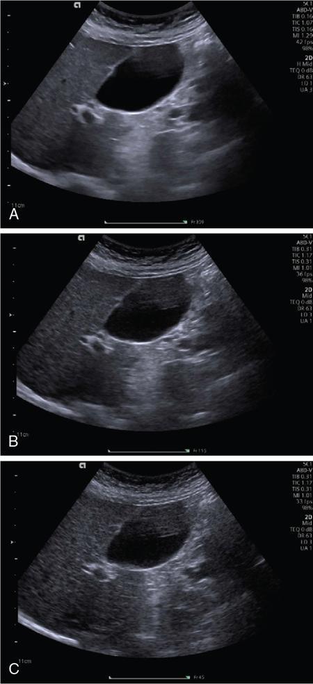
Tissue harmonic imaging
Principle of harmonic imaging
Advantages of harmonic imaging
Applications of harmonic imaging
Limitations of harmonic imaging
Safety of THI
Differential tissue harmonic imaging
Compound imaging: Frequency and spatial compound imaging
Frequency compound imaging
Spatial compound imaging
Code pulse excitation
Adaptive image processing
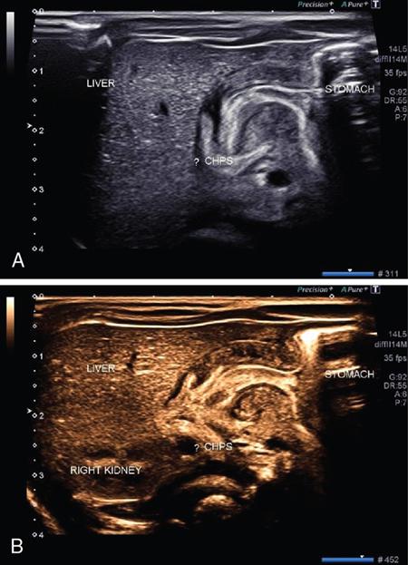
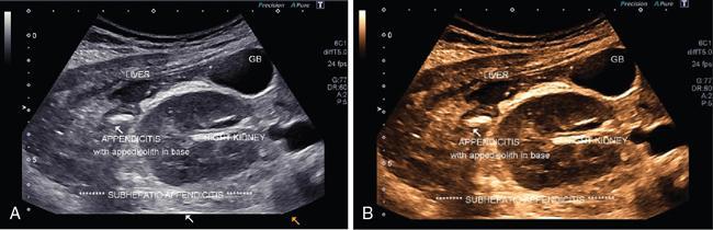
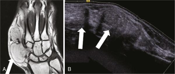
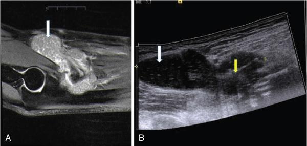
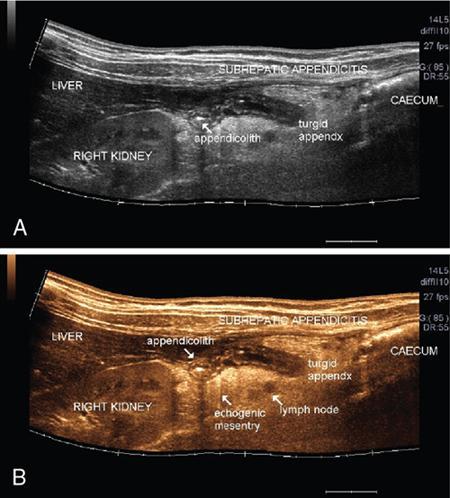
Photopic ultrasound imaging
Extended FOV imaging
Principle and technique of EFOV
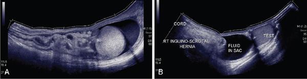
Applications of EFOV
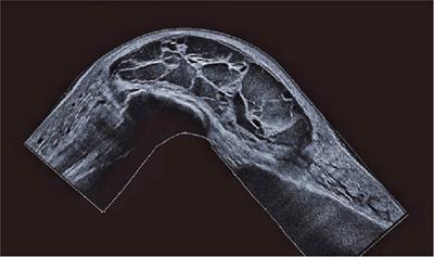
Endoscopic ultrasound
Related posts:


Stay updated, free articles. Join our Telegram channel

Full access? Get Clinical Tree


