The sagittal plane provides extensive longitudinal spinal coverage and permits the simultaneous evaluation of vertebral bodies, intervertebral disks, ligaments, the spinal canal, neural foramina, and spinal cord. When special phased-array coils are used, almost the entire spinal column can be imaged in one view.
Sagittal imaging is supplemented by axial images at selected levels. Axial images are particularly useful for assessing the relationship of a lesion to the dural sac and cord. The imaging plane is oriented parallel to the intervertebral disk surfaces.
The coronal plane rarely adds information in spinal examinations. It is occasionally used to investigate paraspinal abscesses or tumors and to evaluate the joints at the craniocervical junction. Paracoronal (oblique) images may be helpful in evaluations of the cervical intervertebral foramina (see ▶ Fig. 11.18).
The standard slice thickness for spinal MRI is 3 to 4 mm. Axial images with a smaller slice thickness (1–2 mm) may be helpful for evaluating degenerative changes in the cervical spine (e.g., foraminal stenosis).
11.1.2 MRI Sequences
T1w and T2w spin echo (SE) or turbo spin echo (TSE) sequences are most commonly used for routine sagittal imaging of the spine. Axial imaging parallel to the disk space may employ two- or three-dimensional gradient echo (GRE) sequences, depending on the region of interest and clinical question:
GRE sequences: These were often used in the past to shorten the acquisition time. Since the advent of TSE sequences this rationale no longer applies, but GRE sequences are still useful for acquiring thin axial slices of the cervical spine. Also, they are generally less susceptible to cerebrospinal fluid (CSF) flow artifacts than TSE sequences are. GRE sequences cannot supply a true T2w image and can provide only T2*w contrast. This makes them much more sensitive to field inhomogeneities and susceptibility artifacts than TSE sequences. This disadvantage can, however, be utilized for the detection or exclusion of blood breakdown products. On the other hand, GRE images may overestimate bony narrowing of the spinal canal or intervertebral foramina, depending on the degree of T2* weighting.
Fat-suppressed sequences: These sequences are particularly helpful for detecting vertebral body edema, which may otherwise be obscured by the high signal from fatty bone marrow. The following two techniques are most commonly used:
In the STIR sequence, a modification of the inversion-recovery technique, the null point is adjusted in a way that suppresses the signal from fat. The STIR sequence combines high sensitivity with good anatomic resolution. It should be noted, however, that STIR images must be acquired before intravenous contrast administration because any enhancement could mask signal changes due to edema.
Fat signals can also be suppressed by adding a special presaturation pulse. This technique can be used with both T1- and T2-weighted SE and GRE sequences.
FLAIR sequences: FLAIR sequences are rarely used for spinal imaging. They are less sensitive to intramedullary lesions (e.g., in multiple sclerosis) than they are to supratentorial pathology.
Three-dimensional sequences with very heavy T2 weighting: These sequences are used for the high-resolution imaging of spinal nerves and for detecting thin septations or cysts in the spinal subarachnoid space (e.g., TrueFISP, CISS, FIESTA). With these sequences, the slice thickness can be reduced to the range of approximately 0.5 mm. Their main disadvantage is poor soft-tissue contrast. With proper reformatting, images can be produced that have a myelogram-like appearance (MR myelography).
Magnetic resonance angiography (MRA) sequences: Despite many technical attempts, available MRA sequences do not yet have the necessary resolution for imaging very small spinal vessels.
GRE–echo planar imaging (EPI) sequences: These sequences are used mainly to screen for ischemically induced diffusion changes in the brain. With their very short acquisition time, they can provide useful images even in restless patients. They are, however, very sensitive to local magnetic field inhomogeneities like those occurring at interfaces between bone and soft tissue. For this reason they are not suitable for routine spinal imaging.
The underlying clinical question is an important consideration in selecting the proper sequence:
Degenerative diseases: The imaging of degenerative spinal changes mainly requires high anatomic resolution and acceptable contrast between CSF, bone, and soft tissues. For example, TSE sequences with a high matrix (anatomic resolution), high echo train length (shorter acquisition time), and a long effective echo time (T2 weighting) are a good choice for sagittal T2w imaging. They can provide visually compelling images that clearly differentiate the intervertebral disk, subarachnoid space, and spinal cord.
Intramedullary lesions: The detection of intramedullary lesions requires a different strategy. For example, the sensitivity of T2w TSE sequences to multiple sclerosis lesions is reduced by increasing the echo train length (turbo factor) or increasing the degree of T2 weighting. Use of the magnetization transfer (MT) technique is helpful, however. STIR images (see above) also have high sensitivity to intramedullary lesions in multiple sclerosis.
Pitfall
A good general rule in intramedullary diseases is that the contrast between diseased and healthy spinal cord tissue is much less important than high anatomic resolution. Sequences that provide the most visually appealing images are not necessarily the first choice when it comes to lesion contrast.
11.1.3 Contrast Agents
Gadolinium contrast is generally unnecessary in the diagnosis of degenerative or traumatic disorders but may be helpful in differentiating between postoperative scar tissue and a herniated disk. Contrast administration is mandatory in searching for neoplastic or inflammatory diseases in the spinal canal ( ▶ Table 11.1). Areas of faint enhancement in the vertebral bodies are sometimes obscured by the bright signal from fatty bone marrow. The use of fat-suppressed T1w sequences may be necessary in these cases.
Physiologic enhancement | Pathologic enhancement |
|
|
11.2 Spinal Column
11.2.1 Vertebrae
The human spinal column consists of 33 vertebrae that are numbered sequentially by region from above downward. It is subdivided into cervical, thoracic, lumbar, sacral, and coccygeal regions. There are seven vertebrae in the cervical spine (C1–C7), 12 in the thoracic spine (T1–T12), and five in the lumbar spine (L1–L5). The sacrum is formed by the fusion of five vertebrae (S1–S5) and articulates caudally with the four fused vertebrae of the coccyx (Co1–Co4). The spine has a physiologic lordosis at the cervical and lumbar levels and kyphosis in the thoracic region. The sacrum and coccyx together form a kyphotic curve. ▶ Fig. 11.1 illustrates the “double S-shaped” curvature of the normal spine.

Fig. 11.1 Spinal column in early childhood. Spinal column of a 3-year-old child. Imaging with phased-array coils allows the whole spinal column to be displayed in one image. The vertebral bodies mostly contain hematopoietic bone marrow and have intermediate signal intensity in both T1w and T2w images, while the cortex appears hypointense. The nucleus pulposus of the intervertebral disks in children shows uniform high signal intensity in the T2w sequence. The conus medullaris is already at the T12–L1 level. (a) Sagittal T2w TSE image. (b) Sagittal T1w TSE image.
1 = Sella turcica
2 = Clivus
3 = Medulla oblongata
4 = Dens of axis (ossification center of the dens has not yet fused with the base of C2)
5 = Hypointense CSF flow artifact in the subarachnoid space anterior to the cervical cord
6 = Nucleus pulposus of the C6–C7 intervertebral disk
7 = Lumbar subarachnoid space with CSF and filum terminale
8 = L5 vertebral body
9 = Cerebellomedullary cistern
10 = Spinous process of C7
11 = Fatty tissue in the posterior epidural space
12 = Conus medullaris
13 = L1 vertebral body
Each vertebra from C3 to L5 consists of an anterior body and a posterior arch, which together enclose the spinal canal ( ▶ Fig. 11.2). The vertebral body is shaped like a short cylinder whose flat surfaces are formed by the upper and lower endplates. Each vertebral arch consists of paired roots called pedicles, lateral masses with the superior and inferior articular processes, transverse processes, posterior laminae, and spinous processes. The cross-sectional shape of the bony spinal canal is triangular in the cervical and lumbar vertebrae and round in the thoracic vertebrae. The inner diameter of the bony spinal canal decreases in the craniocaudal direction. The normal sagittal diameter in adults is approximately 15 to 16 mm at the T1–T2 level and approximately 12 mm in the lumbar spine.

Fig. 11.2 Structure of the vertebral arches. The vertebral arches of the cervical, thoracic, and lumbar vertebrae each consist of a pedicle, transverse process, lateral mass, and lamina. (a) Cervical vertebra. (b) Thoracic vertebra. (c) Lumbar vertebra.
The superior and inferior articular processes of adjacent vertebrae form the facet joints. The orientation of the articular facets varies at different levels.
The pedicles of two adjacent vertebrae together form an opening on each side called the intervertebral foramen. Located posterolateral to the vertebral body, these foramina are the openings through which the spinal nerves exit the spinal canal ( ▶ Fig. 11.3). The intervertebral foramina are bounded anteriorly by the vertebral body and elsewhere by the pedicles of the two adjacent vertebral bodies, the facet joint, and partly by the ▶ ligamentum flavum.

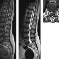
Fig. 11.3 Axial images of the lumbar spine. T2w TSE sequence. Axial images of the lumbar spine and thoracolumbar junction in a 37-year-old subject at levels T12–L1 (a), L3 (b), and L3–L4 (c).
(a) The conus medullaris is already markedly narrowed at the level of the T12–L1 intervertebral disk and is centered in the dural sac. The ventral and dorsal roots of the spinal nerves leave the conus in a somatotopic sequence. The lumbar fibers occupy the lateral part of the cauda equina while the sacral and coccygeal fibers are medial. (b) Section through the lower portion of L3. The L3 spinal ganglion is visible in the L3–L4 intervertebral foramina on both sides. (c) At the level of the L3–L4 intervertebral disk, the L3 nerve root is already in the lateral part of the foramina. The L4 spinal nerves are already in the anterior subarachnoid space on their way to the foramina below.
1 = Left L1 nerve root
2 = Ventral roots in the cauda equina
3 = Dorsal roots in the cauda equina
4 = Conus medullaris
5 = L3 vertebral body
6 = Right L3 spinal ganglion in the intervertebral foramen
7 = Right L4 nerve root in the lateral dural sac
8 = Spinal nerves of the cauda equina
9 = Annulus fibrosus of the L3–L4 intervertebral disk
10 = Nucleus pulposus of the L3–L4 intervertebral disk
11 = Right L3 nerve root (extraforaminal)
12 = Right L4 nerve root in the lateral dural sac
13 = Superior articular process of L4
14 = Facet joint
15 = Inferior articular process of L3
16 = Ligamentum flavum
11.2.1.1 Cervical Vertebrae
The first and second cervical vertebrae (C1 and C2) present special features. The C1 vertebra (the atlas) consists basically of a ring-shaped vertebral arch; it lacks a body in the true sense ( ▶ Fig. 11.4). The reinforced sides of this arch, the lateral masses, support the skull and articulate with the occipital condyles to form the atlanto-occipital joint. Its inferior articular processes articulate with the axis to form the atlantoaxial joint ( ▶ Fig. 11.5). The C2 vertebra (the axis) differs from other vertebral bodies by the presence of a large process, the dens, that projects upward from the body. The dens arises from the anterior part of the vertebral body, and its tip extends almost to the level of the foramen magnum. The anterior part of the upper dens articulates with the anterior arch of the axis (atlantodental joint).

Fig. 11.4 Atlas and axis. (a) C2 (axis), left lateral view. (b) C1 (atlas), superior view.
1 = Lateral mass
2 = Superior articular facet
3 = Inferior articular facet
4 = Anterior arch
5 = Fovea of dens
6 = Anterior tubercle
7 = Posterior arch
8 = Groove for vertebral artery
9 = Posterior tubercle
10 = Dens
11 = Anterior articular surface
12 = Posterior articular surface

Fig. 11.5 Coronal images of the upper cervical spine. Coronal views of the upper cervical spine reformatted from a three-dimensional T2w data set (CISS sequence). (a) Section through the dens of the axis. The joints at the craniocervical junction and the cervical uncovertebral joints are particularly well demonstrated in the coronal plane. (b) Image in a slightly different plane giving an optimum view of the spinal cord. Note how the fiber bundles of the spinal nerve roots leave the cord in groups and run laterally from the subarachnoid space on both sides.
1 = Pons
2 = Atlanto-occipital joint
3 = Dens
4 = Atlantoaxial joint
5 = C2–C3 intervertebral disk
6 = Vertebral artery (V2 segment)
7 = Right C4–C5 uncovertebral joint
8 = Occipital condyle
9 = Lateral mass of C1 (atlas)
10 = Base of C2 (axis)
11 = Uncinate process of C3
12 = Left vertebral artery (V4 segment)
13 = Occiput
14 = Subarachnoid CSF in the foramen magnum
15 = Atlas
16 = Lateral mass of C2
17 = Lamina of C3
18 = Spinal cord, from which the fiber bundles of the spinal nerve roots arise on both sides
The bodies of the C3–C7 vertebrae have a roughly rectangular overall shape ( ▶ Fig. 11.6). They gradually increase in size from C3 to C7. Unlike other vertebrae, they have superior projections called uncinate processes that arise from the upper lateral margin of the vertebral bodies and articulate with the vertebral bodies above to form the uncovertebral joints (see ▶ Fig. 11.5). Another distinctive feature of the cervical vertebrae is the presence of transverse foramina (foramina transversaria) in the transverse processes. These foramina transmit the vertebral arteries and the plexus of vertebral veins ( ▶ Fig. 11.7, ▶ Fig. 11.8). The C7 vertebra is also called the “vertebra prominens” because of its large spinous process. Viewed in the sagittal plane, the articular surfaces of the facet joints in the cervical spine are angled 45º downward and backward from the horizontal.

Fig. 11.6 Parts of a cervical vertebra. (a) Superior view. (b) Right lateral view.
1 = Body
2 = Arch
3 = Pedicle
4 = Lamina
5 = Superior articular process
6 = Inferior articular process
7 = Transverse process
8 = Spinous process
9 = Vertebral foramen
10 = Anterior tubercle
11 = Groove for spinal nerve
12 = Posterior tubercle
13 = Transverse foramen

Fig. 11.7 Sagittal images of the cervical spine. MR images from a 26-year-old woman (a) and a 28-year-old woman (b,c).
(a) T2w TSE sequence. Midsagittal image of the cervical spine covers the region from the craniocervical junction to T5. (b) T1w SE sequence. This image is slightly oblique and cuts the upper cervical spine in the median plane. The entrance to the neural foramen can be identified at the T3 level. (c) T1w SE sequence. Parasagittal image displays the facet joints and neural foramina.
1 = Basilar artery
2 = Clivus
3 = Atlantoaxial joint
4 = Atlas (anterior arch)
5 = Dens
6 = C2–C3 intervertebral disk
7 = C4 vertebral body
8 = Anterior longitudinal ligament
9 = C7–T1 intervertebral disk (annulus fibrosus)
10 = Basivertebral veins
11 = T3–T4 intervertebral disk (nucleus pulposus; the horizontal hypointense line is an early sign of incipient degeneration)
12 = Cerebellar tonsil
13 = Cerebellomedullary cistern
14 = Atlas (posterior arch)
15 = Axis (spinous process)
16 = CSF in the anterior subarachnoid space
17 = Cervical cord
18 = Posterior longitudinal ligament
19 = C7 vertebral body (spinous process)
20 = Supraspinous ligament
21 = Dura
22 = CSF flow artifact in the posterior subarachnoid space
23 = Epidural space with fat and venous vessels
24 = C2 vertebral body (base)
25 = Retropharyngeal space
26 = C7 vertebral body
27 = T1–T2 intervertebral disk (nucleus pulposus)
28 = T3 vertebral body
29 = Medulla oblongata
30 = Occiput (posterior rim of foramen magnum)
31 = Nuchal subcutaneous fat
32 = Splenius capitis muscle
33 = Recess of T3–T4 intervertebral foramen
34 = Occipital condyle
35 = Atlas (lateral mass)
36 = C2–C3 intervertebral foramen with C3 nerve root
37 = Vertebral artery (V2 segment in the transverse foramen)
38 = C4–C5 facet joint
39 = Aortic arch
40 = Vertebral artery (V3 segment, atlas loop)
41 = Inferior articular process of T1
42 = Superior articular process of T2
43 = T2–T3 intervertebral foramen with T2 nerve root (dorsal ganglion)
44 = Pedicle of T3

Fig. 11.8 Axial images of the cervical spine. The C3–C4 neural foramina are clearly visualized in both images. Compared with the GRE image, however, the TSE image shows marked CSF flow artifacts in the subarachnoid space, which prevent the differentiation of gray and white matter in the spinal cord. (a) T2w GRE sequence. Axial image at the C5 level in a 26-year-old woman. (b) T2w TSE sequence. Axial image through the inferior margin of the C3–C4 intervertebral disk in a 46-year-old woman.
1 = Dura (the arachnoid is directly apposed to the dura and is not defined as a separate structure)
2 = CSF in the subarachnoid space (note that the GRE images are almost free of CSF flow artifacts)
3 = Vertebral artery in the transverse foramen
4 = Spinal nerve in the intervertebral foramen
5 = Ventral root of spinal nerve (intradural part)
6 = Dorsal root of spinal nerve
7 = Spinal cord (butterfly-shaped gray matter of the cord appears as a hyperintense structure)
8 = Central part of intervertebral foramen with spinal nerve
9 = Articular surface of facet joint (in the axial plane, the articular surfaces are almost parallel to the posterior margin of the vertebral bodies; the inferior articular process of C3 is anterior, the superior articular process of C4 is posterior)
10 = Subarachnoid space with CSF flow artifacts and nerve roots
Tips and Tricks
Viewed in axial section, the articular surfaces are almost parallel to the posterior margin of the vertebral body. Each of the superior articular processes is anterior to the inferior process. Thus, the anterior articular processes seen on axial images belong to the vertebra below while the posterior articular processes belong to the vertebra above (see ▶ Fig. 11.5, ▶ Fig. 11.7, and ▶ Fig. 11.8).
11.2.1.2 Thoracic Vertebrae
The thoracic vertebral bodies are roughly triangular in outline and are slightly wedge-shaped when viewed in sagittal section. They gradually increase in height from above downward. The articular surfaces of the facet joints in the thoracic spine are oriented almost in the frontal plane ( ▶ Fig. 11.9). The thoracic vertebrae articulate with the ribs on the vertebral body itself (superior and inferior costal facets) and on the transverse process (transverse costal facet). The spinous processes in the midthoracic spine are long, slant downward, and overlap one another like shingles on a roof.

Fig. 11.9 Parts of the thoracic vertebrae.
1 = Spinal canal
2 = Body
3 = Pedicle
4 = Intervertebral foramen
5 = Spinous process
6 = Transverse process
7 = Superior articular process
8 = Inferior articular process
9 = Superior costal facet
10 = Inferior costal facet
11 = Transverse costal facet
11.2.1.3 Lumbar Vertebrae
The five vertebral bodies in the lumbar spine are roughly bean-shaped. They are larger than in the cervical and thoracic vertebrae in conformance with the greater weight-bearing loads at the lumbar level (see ▶ Fig. 11.2). Because the transverse processes of the lumbar vertebrae are actually rudimentary ribs, they are also called “costal processes” ( ▶ Fig. 11.10). The articular surfaces of the facet joints have an approximately sagittal orientation in the upper lumbar spine and face obliquely outward in the lower lumbar region (see ▶ Fig. 11.3 and ▶ Fig. 11.10). The spinous processes of the lumbar vertebrae are powerfully developed and project straight backward.

Fig. 11.10 Parts of a lumbar vertebra. Superior view.
1 = Body
2 = Spinal canal
3 = Arch
4 = Pedicle
5 = Costal process
6 = Superior articular process
7 = Spinous process
Related posts:

Stay updated, free articles. Join our Telegram channel

Full access? Get Clinical Tree


