Chapter 1: Case reviews 1–18
- 2.
a. The top of the screen is inferior on the patient.
- b.
The uterus is anteverted with the fundus directed anteriorly (screen left on Fig. 4 ).
- c.
The uterus is neither anteflexed nor retroflexed.
- b.
- 3.
a. The posterior segment, though superior relative to the transducer
- b.
The anterior segment, though superior relative to the transducer. If the uterus was retroverted/retroflexed, the opposite segments would be at the top and bottom of the screen on the sagittal plane.
- b.
- 4.
a. This is transperineal in a ML sagittal plane. The image is as if looking up the patient from the distal urethra, starting inferiorly. Therefore, the top of the screen is inferior. The bottom of the screen is superior. Screen left is anterior. Screen right is posterior.
- b.
This is transperineal of a cut 90 degrees to the A plane (orthogonal to the A plane at the dot as if looking anteriorly from behind the urethra); therefore, the cut is coronal of the urethra. The top of the screen is inferior.
- c.
This is transperineal of a cut coronal to the dot seen on the A plane, as if looking from one side of the urethra to the other (green line); therefore, the cut is a transverse cut of the urethra. Screen left is anterior. Screen right is posterior. Screen top is the patient’s left. The bottom of the screen is the patient’s right.
- d.
Superior
- e.
Superior
- f.
Anterior
- g.
Right
- b.
- 5.
Because the mesh is posterior to the CRP location.
- 6.
The transducer should be angled anteriorly toward the patient’s head by bringing the handle down to bring the fundus into view of this anteverted uterus.
- 7.
Though thin, there are distinct layers—the hyperechoic basal layer (a), the hypoechoic functional layer (b), and the hyperechoic central cavity (c)—created by the two apposing walls of the central cavity. Therefore, this demonstrates the early proliferative phase. The endometrium is often erroneously called a “stripe” but, because it changes by the day in appearance, that term should be removed from reporting descriptive terminology. There are other cases at other phases presented in this workbook.
- 8.
The letter “d” is pointing to a loop of small bowel in cross-section (as if it is coming at you).
- 9.
No. It should be moved up to the uterus level. This would improve the resolution of the anatomy at this level. Additionally, the depth of view for the image could be improved by decreasing the field of view, since half the screen is imaging bowel and our area of interest is the uterus.
- 10.
The uterus is retroverted.
- 11.
This is the anterior segment directed back posteriorly.
- 12.
Inferior
- 13.
Superior
- 14.
Posterior
- 15.
Anterior
- 16.
The transducer should be angled posteriorly toward the patient’s feet to bring the fundus into view of this retroverted uterus.
- 17.
The endometrial segments are more obscured on this image. Though the functional component is now thickened, there remain three distinct layers—the outer hyperechoic basal layer (gold), the now thickened functional layer, isoechoic to the basal layer (green), and the hyperechoic central cavity (red)—created by the two apposing walls of the central cavity; therefore, this demonstrates the late secretory phase.
- 18.
The CRP (red dot) on the B plane is placed on the left lateral echogenic focus; therefore, the A plane is sagittal at that left side with the white dot CRP corresponding to that same echogenic focus. The light blue dot CRP is the coronal cut through the uterus at that same level and the rendered image demonstrates the hyperechoic foci at the bilateral isthmus locations, proving the coil is correctly placed.
- 19.
The perspective for this image is as if one is looking from posterior to anterior of the pelvic floor at a transverse cut of the urethra and mesh. The patient’s right side is on the left of the screen.
- 20.
c. Unless the entire volume set is present, the relative location of the mesh as compared to the urethral segments would not be known.
- 21.
The mesh is located at the proximal urethra. Since the urethra is only 3–4 cm long and a small mesh placement difference can alter the effectiveness of the urethral/bladder function, the level should be reported on all cases.
- 22.
A curvilinear, hyperechoic structure is visualized posterior and lateral to the urethra, consistent with history of former SPARC sling placement. Of note, the symmetric sling is located at the proximal (not mid) urethra in close proximity to the bladder neck.
A small, round hyperechoic structure is seen in the posterior, proximal urethral wall on sagittal view, and is also visualized on coronal view and with 3D reconstruction. This does not change throughout the exam, suggesting the possibility of a foreign body such as a suture in the posterior urethral muscularis.
- 23.
a. Myometrium
- b.
IUD stem
- c.
IUD strings
- d.
Cornua
- b.
- 24.
Measurements can be made using the calipers along the side of the images. The uterus is enlarged measuring 5.7 × 11.8 × 8.3 cm. The normal uterine volume changes throughout the menstrual cycle and ranges from 70 to 200 cm 3 . The formula to calculate volume is the prolate ellipsoid volume calculation, which is L × W × H × 0.52; therefore, the volume of this uterus is enlarged at 290.3 cm 3 .
- 25.
b. The posterior/fundal myoma displaces the endometrium anteriorly giving the false impression of anteflexion.
- 26.
c
- 27.
d
- 28.
c
- 29.
a. 1. Inferior
- 2.
Left
- 3.
Superior
- 4.
Right
- 2.
- b.
1. Inferior
- 2.
Posterior
- 3.
Superior
- 4.
Anterior
- 2.
- 30.
The most likely etiology of the complex primarily cystic appearing mass is a hemorrhagic follicular cyst with a dependent clot. While it looks large on the screen, it measures very small at 1.5 × 0.885 × 1.38 cm with a volume of 0.9526 cm 3 . The patient was re-examined 6 weeks later at which time it all had resolved.
- 31.
a. 2.3 × 1.5 cm. This ovary appears within normal limits in size.
- b.
4.1 × 3.6 cm. This ovary appears enlarged.
- c.
No. The right ovary has a normal echo pattern. The left ovary demonstrates a diffuse heterogeneous dense appearing echo pattern.
- b.
- 32.
a. Yes, the ovarian contour is smooth.
- b.
No, the contour is circumferentially irregular.
- b.
- 33.
a. Normal small follicles are seen.
- b.
There is a paucity of follicles seen.
- b.
- 34.
Though there is a normal circumferential flow pattern around one small follicle, most of the ovary has inconsistent vascularity.
- 35.
RI is an additional tool that when abnormally low, less than 0.4, may raise the index of suspicion for quickly forming hypervascularized tissue, such as a neoplasm. The RI in this case was high at 0.61, decreasing, but not eliminating, the concern for malignancy.
- 36.
c. The right ovary was resected. At pathology, the sonographic bulky, enlarged, and dense area of the left ovary was found to be a dysgerminoma with corresponding abnormal vascularity.
- 37.
The acquisition sweep was ML sagittal, as seen on the A plane.
- 38.
The CRP is seen at the mid posterior vaginal wall.
- 39.
The CRP could be moved to the screen left at mid-urethra on the A plane, which would move through the volume on the orthogonal B and C planes. Alternatively, the CRP could also be moved towards screen left on the C plane to the mid-urethra.
- 40.
There is no evidence of avulsion, although there are several aspects of the volume set that would have improved visualization of the entire PVM complex had the following three instrumentation steps been taken. First, the A plane could have been rotated to the left on the screen by shifting the Z-axis knob. Second, the C plane screen right side could have been rotated upward also with the Z-axis knob to enhance symmetry of the 3D rendered image. Third, if the green line of reference was moved up on the screen (inferior on the body), it would have added the final aspect of the PVM attachment at the pubic rami.
- 41.
a. The typical sonographic venous appearance is one of low visibility, generally measuring 1–2 mm. AP diameter > 5 mm is considered abnormal.
- b.
Normal vessels likely increase in diameter with Valsalva and resume normal size at rest. Dilated venous structures with Valsalva may demonstrate increased AP diameter, as seen on Fig. 31 , where the diameter (gold lines) measures 6.5 mm with Valsalva. This same increase in diameter may be accomplished when a patient has prolonged periods of standing up or heavy lifting.
- c.
Pelvic Congestion Syndrome
- d.
This appearance of diffusely dilated vessels is indicative of pelvic congestion syndrome, which has a prevalence of 39%. It is associated with an increasingly incompetent ovarian vein varices that results in reduced venous clearance and stasis. As the venous dilatation worsens, the vessels become diffusely tortuous as flow becomes retrograde. Patients may describe the fullness as if their “bottom is going to fall out” and occurs more frequently in multiparous patients for unclear reasons. The patient’s chronic pelvic pain will usually reflect the degree of dilatation seen sonographically.
When dilated, abnormal venous structures can be serpiginous in contour and unilateral or bilateral. Other imaging, including CT and MRI, also well visualize the altered dilated vasculature with this condition.
- b.
- 42.
The uterus is anteverted.
- 43.
b
- 44.
Using the calipers along the side of the images, the smooth-walled central cavity lesion measures 4.3 × 1.8 × 2.5 cm.
- 45.
Doppler Color Flow pattern is the key to the diagnosis. The transverse image demonstrates a single anterior feeder vessel entering centrally ( Fig. 33 ), the finding c/w a large endometrial polyp as opposed to the typical peripheral vascularity of a myoma.
The patient was undergoing evaluation for infertility, the polyp was resected, and the patient became pregnant 2 months later.
- 46.
a. Endometrial lesions are found on all three cases, ranging from × to 40 mm, some originating from the anterior, some from the posterior, and some from both aspects of the endometrium.
- b.
Fig. 35 demonstrates a single lesion seen on both planes.
- c.
It demonstrates increased internal central, not peripheral, vascularity within each lesion.
- d.
Yes. A thin basal layer is seen only, except the abnormal segments.
- e.
No, the vascularity is a qualitative sample of vessel presence.
- f.
Yes
- b.
- 47.
c
- 48.
Hydrosalpinx
- 49.
The sweep plane (A) is midline sagittal.
- 50.
e
Chapter 2: Case reviews 19–35
- 2.
The IAS disruption is from 9 to 1 OC, with elevation of the central mucosa toward the defect.
- 3.
c
- 4.
a. It is circumferentially smooth.
- b.
Yes
- c.
This is called “posterior acoustic enhancement,” also known as “enhanced through transmission,” indicating little absorption of sound as it traveled through the lesion by the increased echogenicity beyond the lesion.
- b.
- 5.
a. The septae seen are variable in thickness.
- 6.
It would be incorrect to call this lesion a “cyst.” It is complex primarily solid in appearance with diffuse low-level echogenicity and multiple thick and thin septae noted.
- 7.
b
- 8.
a
- 9.
a. Bladder
- b.
Vagina
- c.
Rectum
- d.
Urethra
- b.
- 10.
c. Best seen on the C plane.
- 11.
a
- 12.
It measures 5 × 10 × 10 mm.
- 13.
a. Both (red arrows)
- b.
Small rectocele at the distal posterior vaginal/rectal interface
- c.
Left pubovisceralis muscle complex
- b.
- 14.
Neither image is right or wrong.
- 15.
a. Endometrial functional layer
- b.
Endometrial basal layer
- c.
Central cavity wall
- d.
Extra-uterine transverse cut of bowel loop
- b.
- 16.
c
- 17.
b
- 18.
a. The uterus is anteverted.
- b.
The uterine echo pattern is diffusely heterogeneous and appears unlike the normal uterus.
- b.
- 19.
a
- 20.
a. Typically, however, flow pattern of this condition appears randomly scattered.
- 21.
c. It is not uncommon to find concomitant leiomyomata; however, no demonstrable myomatous lesions are seen in this patient.
- 22.
Using the calipers along the side of the image, the transverse width measures 10 cm.
- a.
The normal nulliparous uterine transverse width measures approximately 4–5 cm.
- b.
i. The lesion is central in location, within the endometrial cavity.
- ii.
The lesion is irregular and multilobular in contour.
- iii.
The lesion is oblong and multilobular in shape, with the widest aspect at the transverse plane.
- iv.
The echo pattern is complex primarily solid in echo pattern, with a rim of hypoechogenicity around most aspects of the mass, except the left lateral aspect where the lesion appears to be contiguous with the myometrium (gold arrows). All is thought to be within the endometrial cavity.
- ii.
- a.
- 23.
b
- 24.
d
- 25.
d
- 26.
The volume measures 6.523 cm 3 when calculated manually, which correlates with the volume on the image of 6.568 cm 3 done at the time of the exam.
This demonstrates that measurements can trustfully be calculated post exam using the prolate ellipsoid formula from two planes; therefore, one can measure the L × H × W × 0.52 to obtain the parameters and volume. This assumes one does not measure, say, the transverse width twice instead of the AP diameter; so, one must be sure what the directions are on each plane.
- 27.
a and e. Describe the mass as anechoic, indicating it is simple, with a smooth though irregular border extending toward the patient’s left side. The ultimate diagnosis requires histochemical assessment.
- 28.
The volume of this ovary is measured on Fig. 56 and is markedly increased at 154 mL (cm 3 ).
- 29.
a. Smooth
- b.
Bilobular
- c.
Heterogeneous
- b.
- 30.
Both and, cumulatively, markedly increased.
- 31.
RI = 0.2
The RI of this ovary is abnormal. Sometimes, a benign process changes flow patterns to have a low RI. A typical corpus luteum, for example, has a low RI as it develops quickly. A malignant lesion tends to quickly form new vessels also with a low RI; so, in the context of imaging, a first exam often elicits a referral for a repeat exam in the presence of a mass with a low RI.
It is crucial to repeat the imaging exam in enough time for a potential corpus luteum to resorb. It is reasonable to schedule after 8 weeks or at least two full menstrual cycles. Rushing to repeat another exam prior to that time may result in continued concerning 2D findings, Color Power Doppler, and abnormal spectral waveform patterns.
These findings persisted on repeat exam and she underwent surgical removal of the mass. The pathologic diagnosis for this lesion was a borderline tumor.
- 32.
a. They are the right and left pubovisceralis muscle complex, which is most optimally seen at the midlevel.
- b.
Screen left on a transverse cut is right on the patient, as if looking “up” the patient (from inferior to superior).
- c.
It is widely disrupted from 8 to 2 OC (green arrows), with elevation of the central mucosa (CM) toward the defect.
- b.
- 33.
3.38 × 2.69 cm
- 34.
More
- 35.
2D EV imaging of the IAS and perianal tissue demonstrates a disruption from 8 to 2 OC at the midlevel IAS, as seen by the presence of the pubovisceralis muscle complex posterior and lateral to the IAS. Anterior to the disruption is a poorly demarcated heterogeneous perianal soft tissue area with irregular contour, and a central area measuring approximately 3.4 × 2.69 cm. Multiple punctate echogenic foci are noted within this central soft tissue area. 2D Color Power Doppler elicits diffusely increased vascularity throughout this area. 3D volume render demonstrating profound accumulated increased vascularity ( Fig. 65 ).
Findings are c/w a perianal abscess extending from a severe IAS disruption and vaginal tear.
Over the next 8 weeks, the patent was treated medically with various antibiotics and the abscess gradually reduced in size and the patient slowly improved.
- 36.
b
- 37.
Yes, the stem is central.
- 38.
No. Though the stem is central ( Fig. 67 ), the arm extends beyond the cavity into the left myometrium ( Fig. 68 ).
- 39.
It is at the mid IAS by demonstration of the adjacent pubovisceralis muscle (PVM) complex. All quadrants of the IAS are measured, demonstrating relative symmetry with the central mucosa.
- 40.
a. Central mucosa (CM)
- b.
Left pubovisceralis muscle (PVM) complex
- c.
Internal anal sphincter (IAS)
- b.
- 41.
Label E is the patient’s right side and F is left as if you are looking inferiorly to superiorly.
- 42.
No. The absence of the pubic and anterior/lateral PVM makes this diagnosis inconclusive. To be complete, another 3D volume sweep needs to be performed with an angulation of the line of interest from symphysis to the puborectalis level wide enough sweep angle to include all anatomy anteriorly to posteriorly. This is usually accomplished with the CRP moved to symphysis and the plane rotated on the Z-axis.
- 43.
Appreciating the 90-degree planes’ yin-yang appearance of an acutely formed hemorrhagic clot is related to knowing what direction is where on each plane of an EV image. When a clot forms, it lies at the dependent portion of the hemorrhage at the dependent portion of the patient in a layer/layer (fluid/fluid) pattern. So, if the patient is lying down, the dependent aspect is inferior (always at the top of the screen when the exam is EV). What is seen in the sagittal versus transverse plane is related to the side locations. In the sagittal plane, screen left is anterior (screen right posterior) and in the transverse plane, screen left is the right side of the patient (screen right is the left side of the patient).
Fig. 72 a is labeled with correct directions on the patient as related to each aspect of the clot of the sagittal and transverse plane.
- 44.
a. Yes. The typical normal ovary measures 1 × 2 × 3 cm with a volume of approximately 3.12 mL (cm 3 ). Globally, this ovary measures 1.5 × 2 cm.
- b.
The contour of the ovary is smooth in appearance; the hyperechoic subcomponent is eccentric yet also smooth in contour within the ovary.
- c.
If her last menstrual period (LMP) was 1 week ago, her ovary would be in the follicular phase and demonstrate several small follicles. No follicles, normal or abnormal, are seen within the ovary on these cuts; however, if a higher-frequency transducer could have been used, there may have been a few small follicles visualized.
- b.
- 45.
a
- 46.
Too high
- 47.
c
- 48.
It is not entirely visualized by transperineal imaging due to distal apposition of the mucosa and possible minimal transducer compression; however, the urethra appearance is typical.
- 49.
This is an example of how important assessing anatomy in two planes is, especially in the presence of what may be perceived to be an abnormality. The finding is not uncommon in a partially full bladder.
- 50.
a. Indistinct
- b.
Endometrial periphery
- c.
16 mm
- d.
23 mm
The endometrium appears thickened with a smooth contour and a relatively homogeneous echo pattern. The anteroposterior (AP) diameter measures 23 mm, whereas the typical measurement would be 5–7 mm at the early proliferative phase. The endometrial layers are indistinct with the isoechoic thin basal layer noted peripherally only at the lower endometrium. The basal layers are being measured by the calipers at 1.5 and 1.7 mm.
- b.
- 51.
Focal peripheral vessels extend centrally into the endometrial mass.
- 52.
c
- 53.
a. The typical bladder wall thickness is 1.5–2.76 mm.
When the bladder is distended, it should not measure more than 3 mm.
When the bladder is empty, it should not measure more than 5 mm.
This bladder thickness is abnormal, ranging 6.1–6.3 mm.
- b.
The AP thickness at the arrow measures 8 mm.
Etiologies for increased bladder wall thickness may include chronic UTI/ infectious cystitis, bladder outlet obstruction, neurogenic bladder, and cystitis from radiation or chemotherapy exposure, and others.
Chapter 3: Case reviews 36–55
- 2.
The transabdominal examination approach is infinitely variable with individualized angulation necessary in order to optimize assessment of the uterus.
- 3.
a. B, C, and D are EV images as evidenced by empty bladder, closer approach to the anatomy, and improved resolution. Image A is a transabdominal image.
- b.
No. Image A demonstrates the measurement of the uterine length suboptimally, and the bladder is not full enough to completely see the uterine fundus. Unless the transducer lines of sight are perpendicular to the endometrium, it will not be optimally assessable even if the uterus is measurable.
- c.
C. The cervical canal is well demarcated because the curvilinear transducer’s lines of sight are hitting both interfaces perpendicularly.
- d.
Correct answer is B, C, and D images. B is secretory phase, C is early proliferative phase, and D is secretory phase.
- b.
- 4.
a. Angled anteriorly. Bring handle down.
- b.
Move halfway out of the vagina and angle slightly anteriorly.
- c.
Move out of the vagina and anteriorly from the vaginal introitus on the perineum to be directly in front of the urethra.
- d.
Move out of vagina, angle perpendicularly [90 degrees to the anal sphincter complex (ASC)] on the vaginal posterior wall (yellow line) toward ASC (unless anorectal transducer is utilized).
- b.
- 5.
a. Anteriorly, with the transducer toward the patient’s head, handle down.
- b.
Posteriorly, with the transducer toward the patient’s feet, handle up.
- c.
Post-menses; the two very thin hyperechoic basilar layers are apposing each other with no visible functional layers.
- d.
Secretory; the functional and basilar layers are isoechoic, relative to each other, and slightly hyperechoic, relative to the myometrium.
- b.
- 6.
a. It measures 10.9 × 14.8 × 14.3 mm.
- b.
Round
- c.
It appears isoechoic to the vagina with several peripheral hyperechoic curvilinear echoes with and without posterior acoustic shadow. Isoechoic structures are difficult to see, so the calcifications can be helpful to get the examiner on the right pathway toward locating lesions.
- b.
- 7.
a. It is posterior.
- b.
It is posterior and inferior.
- b.
- 8.
The B plane, relative to the patient’s body , is coronal through the center reference point (CRP), and the C plane is axial through the CRP.
- 9.
It is not seen on the B plane because the coronal cut (90 degrees, or perpendicular, at the red line on the A plane) is posterior to the urethra.
- 10.
10 × 10 mm
- 11.
d. Myomas can have a range of echogenicity and calcifications.
- 12.
a. What to report: The bladder luminal wall contour is irregular and diffusely jagged in contour with markedly abnormal thickening, measuring 9.3 mm. Remember, the maximal wall thickness of a partially full bladder should be 5 mm or less.
- 13.
Bladder
- 14.
a. The caliper units along the right side of the Color Power Doppler of Fig. 92 are 0.5 cm increments, with every two lines measuring 1 cm units. The left (normal) labium ( Fig. 90 ) measures 2.69 × 1.43 × 2.96 cm with a volume of 5.48 cm 3 . The right (swollen) labium ( Fig. 92 ) measures approximately 3.5 × 2.5 × 2.25 cm with a volume of 10.23 cm 3 , calculated by using the prolate ellipsoid formula of (L × W × H × 0.523); therefore, one can confidently say that the right labium is about twice the size of normal.
- b.
Diffuse. What to report: Color Power Doppler demonstrates a diffuse markedly increased pattern of flow of the enlarged right labium, indicating an extensive inflammatory process, especially as seen cumulatively on the profoundly increased vascularity of the 3D rendered images. Follow-up exams demonstrated gradual reduction of the hypervascularity with antibiotic treatment.
- b.
- 15.
b. The surrounding posterior and lateral pubovisceralis muscle complex (Label C) is the adjacent midlevel internal anal sphincter (IAS) landmark.
- 16.
a. Sagittal
- b.
Transverse (axial) at the mid-internal anal sphincter (IAS) (see gold arrows at PVM complex on both A and B planes).
- c.
Coronal
- d.
The CRP should be moved screen left on the A plane, which is proximal on the ASC, to just before the anal angle (red *).
- b.
- 17.
Parallel. In this case, abnormal vessels can be clearly visualized in a parallel pattern anterior and posterior to the endometrium on the sagittal images (screen left, top, and bottom). When the transducer is turned 90 degrees to a transverse cut, those vessels can be seen entering into the central area of an endometrial lesion in the zoomed transverse plane (blue arrows, screen right, top, and bottom). This indicates a classic endometrial polyp appearance. The lesion is surrounded by a thin isoechoic post-menses basal layer component (gold arrow) of the endometrium on the transverse cut.
- 18.
e
- 19.
a. 11–12 o’clock (OC)
- b.
11–1 OC
- b.
- 20.
Both. Note that the normally round central mucosa extends towards the defect on both images.
- 21.
Though B demonstrates a portion of the PVM (gold arrow), the sector width during the exam was set wider for A (blue arrow).
- 22.
It would be better. A higher- frequency transducer has higher resolution images.
- 23.
b
- 24.
a. Disruption is from 10 to 2 OC.
- b.
There is an elevation of the central mucosa (CM) toward the defect.
- c.
False. The perianal tissue is abnormally distorted and heterogeneous, suggesting the presence of scarred tissue.
- b.
- 25.
a
- 26.
e
- 27.
a. Widens
- b.
Both
- c.
No
- d.
No
- e.
Yes
- b.
- 28.
a. No.
- b.
Inferiorly
- c.
No. The bladder has an irregular bilobular bulky appearance that expands with Valsalva. It prolapses inferiorly. There is no evidence of enterocele.
- b.
- 29.
A
- 30.
a. Yes. It appears to extend through the cuff.
- b.
It lies directly adjacent to the left ovary but is hard to tell if they are adhered on the initial image. With manual lower pelvic compression, the two structures separated on real time.
- b.
- 31.
a. Sagittal midline
- b.
Transverse mid-uterus
- c.
Coronal of uterine body
- b.
- 32.
The A image is always the sweep plane, but what plane that is will be determined by the examiner in how they hold the transducer. Midsagittal is the standard cut for the sweep plane in uterine assessment and the typical sweep angle is about 75 degrees to capture the whole uterus with the slowest sweep speed setting to obtain the highest resolution. The center reference point (CRP) indicates the location at which the B plane is cut at 90 degrees, or perpendicular (transverse cut) to the A plane, and C plane is coronal to the A plane and a coronal cut of the uterus.
- 33.
The C plane is the only view that shows the entire IUD in this case. Since the coronal C plane is not seen on the 2D vaginal approach, unless the uterus is in a neutral position, seeing the entire IUD on one plane may not be possible.
- 34.
The coronal C plane is most reliable if the original sweep plane is midline sagittal.
- 35.
It is pointing to a commonly seen nabothian cyst.
- 36.
No. Only the stem is within the cavity. Note that the left arm is extending into the left portion of the myometrium. Only identifying the presence of the stem will often miss this diagnosis.
- 37.
Posterior
- 38.
Each horizontal-to-horizontal distance caliper along the side of each image is 1 cm. Each horizontal-to-dot distance is 0.5 cm. The left ovary is enlarged, measuring 4.2 × 4.2 × 4.3 cm using the markers on the side of each image, with a volume of 40.38 cm 3 (using the prolate ellipsoid volume formula of L × W × H × 0.52. This was acquired from the calipers along the image of the 3D volume set. Remember, normal ovarian measurements should be around 1 × 2 × 3 cm with a volume of × cm 3 .
- 39.
c. The only anechoic components of this ovary are a few peripheral follicles. Otherwise, the ovary demonstrates diffuse low to midlevel echoes, a thick partial vertical septum, and a solid round component at the inferior aspect of the abnormal appearing ovary.
- 40.
All three RIs are abnormally low at 0.20, 0.22, and 0.26. Remember, normal RI for the ovary should be above 0.4. Added concern is raised for malignancy when septae demonstrate increased vascularity, as is seen here. At surgical pathology, this mass was found to be a borderline tumor.
- 41.
Each line-to-dot distance is 0.5 cm; so, one can appreciate the distance of the mesh from the perineum at about 1.5 cm. The purpose of this image and cine loop is to demonstrate how mesh can be well seen with a high-frequency transducer. To determine the location of the mesh, relative to the urethra would be better presented with a 3D volume set; however, it is evident that the surgical mesh placement is too distal.
Chapter 4: Case reviews 56–74
- 2.
a. It measures 3.75 cm (green lines), which is normal, as the average urethra is 4 cm. Remember, that is only 1.5 inches, but with the standard small field of view, it always looks much larger than it really is.
- b.
It measures 7.5 mm.
- c.
The arrow is pointing to the nearly empty bladder (superior to the urethral neck).
- b.
- 3.
The AP measurement is reduced to 4 mm (B) from the original measurement of 7.1 mm (A) at rest.
- 4.
a. Yes
- b.
Yes
- b.
- 5.
Midlevel
- 6.
Yes (gold lines)
- 7.
b. The uterine wall is symmetric in appearance at the screen top. The measurements of the 12, 3, 6, and 9 OC aspects of the IAS appear symmetric. The focal zone indicator is hard to see as it overlies increased echoes of the anatomy behind it, but it is at the level of the puborectalis muscle (green arrow) posterior to the IAS.
- 8.
2 is the level seen on the C plane image, which is not the IUD, but instead, the acoustic shadow created by the absorbing high-density IUD. One would have to parallel shift the plane or move the CRP (green arrow) on the volume set to the IUD stem to see the actual IUD and not the acoustic shadow.
- 9.
Approximately 5 mm
- 10.
Each of the caliper segments is 0.5 cm; therefore, the distance from the transducer to the rectum is 2.1 cm. Though the perianal tissue is less than 1 inch in distance in this case, it is highly abnormal to be this swollen, distorted, and heterogeneous and should be reported in detail.
- 11.
a. Fig. 129 . Gold arrows surround the EAS, which is at the same level as the distal IAS.
- b.
Fig. 130 . The mid IAS is located at the surrounding PVM complex (blue arrows).
- b.
- 12.
What to report: There are multiple findings.
- a.
There is an irregular oval-shaped poorly circumscribed heterogeneous area visualized between the poorly distinguished posterior vaginal wall (screen top) and the anterior segment of the rectum.
- b.
It measures 4 × 2.2 cm.
- c.
The echo pattern is complex primarily solid in appearance.
- d.
Color Power Doppler elicits marked diffuse hypervascularity, especially within the central component of the area.
Fig. 129 , located at the EAS level, demonstrates an intact sphincter at this level. Fig. 130 , however, which is located at the mid IAS, demonstrates an IAS disruption at 10 OC and a second disruption with a hypoechoic tracking at 12 OC, both with elevation of the central mucosa (CM) (labeled white arrows on Fig. 131 ). Findings are consistent with a perianal abscess, IAS disruptions, elevation of the CM, and a developing partial rectovaginal fistula directly anterior to IAS disruption at 12 OC.
- a.
- 13.
a. Yes. There is an IUD present within the central cavity. The IUD arms were seen within the endometrial cavity though not presented here.
- b.
Yes. The line of reference was brought down to the area of interest on the A and B planes, which was directly above the stem.
- c.
It is at the left lower uterine segment (LUS). This can be double checked by noting that plane B (transverse cut) has a small on-screen green box icon, which on any (correctly done) uterine transverse cut would be at the patient’s right side (gold arrow). The 3D rendered image (bottom right) displays that same green box icon on the same side as the B plane green box; therefore, it is also the patient’s right. While the examiner usually knows what direction is where on the volume set and rendered images, when pathology is complicated, it is not so intuitive and use of the icons helps tremendously to confirm location.
- b.
- 14.
Fig. 133 demonstrates the location of the protruding IUD through the back wall of the uterus to the anterior edge of the adjacent hypoechoic bowel wall. When looking closely, during and post exam, the CRPs (green arrows) are on the structure to where it was moved from the initial volume center. You might have to get out a magnifying glass to see them! On the A plane, the CRP color is white; on the B plane, it is red; and on the C plane, it is light blue (green arrows). There is an additional way to notice the intersection points of the CRPs. Note that wherever there is a CRP, there are two short lines, one arrowed, along the periphery of the plane cuts. If you connect the two sides of those lines, they go straight across the image and intersect the CRP.
- 15.
The IUD hyperechoic structure, seen as if it is coming toward the viewer on the B plane, is the transverse plane and the CRP color on it is red (green arrow, magnified on zoomed image below); therefore, number “1” is the IUD and the hyperechoic interface numbered “2” is lateral (as are all those other horizontal linear echoes) that likely represents adjacent myometrial and vascular wall interfaces. Fig. 134 demonstrates partial invasion of the IUD into the adjacent bowel wall. Knowing exactly where the second IUD was located allowed the provider to remove it from the bowel wall without incident, which resulted in immediate relief by the patient.
- 16.
The anterior posterior (AP) thickness measures 24.13 mm (red arrow), far exceeding a typical early proliferative stage thickness of the endometrium. The normal endometrial thickness at this stage should be 5–7 mm. The thin basal layer is seen as a thin hyperechoic outer rim of the endometrial complex ( Fig. 135 , gold arrows).
- 17.
b
- 18.
d. The basal layer is very thin (gold arrows) and envelops an isoechoic thickened multilobulated complex that appears primarily solid, not a hypoechoic layer.
- 19.
a. The typical polyp is isoechoic to the endometrial basal layer and hyperechoic relative to the myometrium.
- 20.
With the CRP moved to this area on all three planes, it indeed suggests a well-circumscribed, round hyperechoic structure measuring 8 mm at the right LUS/cervical interface. The B and C planes of Fig. 137 , however, demonstrate that between the transducer and this “lesion” is a normal anechoic nabothian cyst, behind which is a distinct area of enhanced through transmission, which would be present posterior to any anechoic structure and appear round on the axial cut. With a Z-axis rotation of the 3D rendered image ( Fig. 138 ), it looks very real. In fact, however, it is an artifact. Additionally, there is a similar appearance inferiorly of another nabothian cyst. ( Fig. 137 , green arrows)
- 21.
d
- 22.
It is ML, as seen on the CRP placement of B and C planes.
- 23.
b. It should be reported that the distance from the anechoic midline structure to the anterior LUS wall ( Fig. 140 , green line) measures 5 mm. As a cautionary description, in the event of a subsequent pregnancy, this may put the patient at an increased risk for complications, including uterine rupture or placenta acreta.
- 24.
c. Using calipers alongside the image, uterine length measures 6.4 cm and the AP diameter measures 2 cm, both within normal limits for age. The endometrial thickness is thin, as expected, measuring 2 mm. The spiral artery pattern is typically perpendicular to the endometrial interface but should not enter the endometrium. Fig. 142 a demonstrates an abnormal segment of vascularity with a segment crossing the endometrium (green arrow). Though the arrow points to what appears to be abnormal flow across the endometrium, the presumed vessel could not be reproduced and is most likely a flash artifact. Given her age, an endometrial biopsy was performed which was normal. The etiology of her spotting was presumed to be related to pessary use.
- 25.
Yes. Though both stems are present and central within the cavity, they appear very near the cervix (gold arrows), so our recommendation was to follow-up within 3 months to confirm their location. The patient did not return for follow-up.
- 26.
b
- 27.
d
- 28.
a. No. Normal follicles are not seen, but this is only one slice of the ovary and normal follicles may very well be seen in other planes.
- b.
No, the free fluid is minimal (green arrow).
- c.
No, there are diffuse low echoes levels noted; therefore, nothing within the ovary is anechoic (without echoes).
- d.
Yes, suggesting the presence of blood in various stages of resolution (red arrows).
- e.
No, there is “posterior acoustic enhancement” present, which is a misnomer.
A better descriptor for this appearance would be “enhanced through transmission.” The mechanism for this appearance is that the blood within the hemorrhagic cyst does not absorb sound like a solid mass or even normal tissue would; therefore, with the expected automatic near to far field time gain compensation (TGC) increase, the area beyond the cyst appears increased in echogenicity rather than the same, which normal tissue would demonstrate. In this case, though it looks posterior to the ovary, this enhancement is superior to the hemorrhagic corpus luteum on the screen, as the transducer is located inferiorly (at the top of the screen). Enhanced through transmission (arrows) beyond a hemorrhagic corpus luteum is a typical finding of an acute bleed and should be noted in the report as it is sonographic criteria for this finding.
- b.
- 29.
No. It is related to the ever-important location of the center reference point (CRP) on the volume set and not to any pathology at this area. Fig. 148 exemplifies the cuts through the CRP location for each orthogonal plane. The yellow line is the B plane and the green line is the C plane relative to the A plane. The red arrow points to the C plane coronal cut (green line). Note that the straight green line lies above the more curved endometrial/lower uterine segment, which, therefore, would not be seen on the C plane. Instead, the C plane would demonstrate the more hypoechoic myometrium above that central location.
- 30.
Because the CRP perpendicular cut of the transverse B plane is more fundal on the endometrium, as depicted on the A and C center reference points (CRPs). Remember, the colored dots are the CRPs, and are all the exact same point on different planes; however, the A and B planes include adjacent anatomy beyond that CRP, but the B plane, which is perpendicular to the A plane at the intersection of the A and B planes, only demonstrates the transverse fundal cut, not the LUS.
- 31.
The gold arrow is pointing to the bladder (nearly empty).
- 32.
b
- 33.
Fig. 151 . The screen right “stretched out” cavity length measures 13.2 cm. Adding the 1.5 cm thickness of each myometrial outer rim now makes the total length of the uterus 16.2 cm. The A plane ( Fig. 152 ) measurement of the uterus length at approximately 11.2 cm (green line) is 5 cm shorter than a traced length of the curved uterus on Fig. 151 . The other uterine dimensions measured on this volume set include the yellow line measuring the uterine anterior posterior (AP) diameter at 7 cm (sagittal image) and the red line measuring the uterine width at 6.3 cm (transverse); therefore, the uterine volume of 371.5 cm 3 on this patient, calculated using the prolate ellipsoid volume formula, far exceeds a normal nulliparous uterine volume, even with the shorter length used.
- 34.
d. Though the endometrial cavity is hypoechoic relative to the surrounding myometrium, the echo pattern is complex with diffuse small linear echogenic foci. The vagina is normal in appearance and contains no fluid. Findings are consistent with hematometra, an insidious accumulation of long-term menses obstructed at a closed cervix.
- 35.
b. The endometrium is not definitively seen, so cannot be measured. The uterine length and AP diameter are on Fig. 152 . The transverse mid-uterus image is not presented here; however, it measures 5.6 cm in width, which would make the volume of her uterus 153.8 cm 3 , which is more than twice the typical normal uterine volume. The echo pattern is diffusely bulky in appearance with a circumferentially irregular contour. It is heterogeneous though no definitive myomata are appreciated. The echo pattern relationship of the hyperechoic uterus relative to the hypoechoic cervix is abnormal. They should appear relatively isoechoic.
- 36.
a. What to report about the cervix: The cervix demonstrates irregular contour with markedly abnormal punctate echogenic foci seen at the anterior inferior focal area of the mass (small light green arrows). Color Power Doppler ( Fig. 154 ) demonstrates diffuse increased vascularity of the cervix. The Doppler spectral waveform RI ( Fig. 155 ) is abnormal at 0.39 using a 0.40 cut-off threshold for neoangeogenesis. Even though the RI is just under 0.40, it would be considered abnormal. Findings are consistent with her clinically diagnosed cervical carcinoma.
- 37.
a. Left
- b.
Contiguous
- c.
No. There is a second circular 3.5-cm hypoechoic lower uterine segment (LUS) myomatous lesion (labeled as number 2).
- d.
Yes, there is a trace amount of FF present (white arrow).
- e.
Yes, but only at the mid to fundus endometrium. The inferior aspect of the endometrium is obscured by the LUS myoma (number 2).
- b.
- 38.
a
- 39.
a. 1.8 cm
- b.
Color Power Doppler demonstrates minimal peripheral flow. There is no intralesion flow present. The patient remains clinically asymptomatic and desires continued surveillance of the cyst.
- c.
Calcific infiltrates can suggest some degree of chronic inflammation or a complex lesion.
- b.
Chapter 5: Case reviews 75–94
- 2.
a. #2
- d.
#1
- f.
#4
- i.
#3
- d.
- 3.
a. Mid-urethra
- b.
Midsagittal
- c.
Coronal
- d.
Axial
- b.
- 4.
a. 5
- b.
1
- c.
3
- d.
2
- e.
4
- b.
- 5.
(Left image, Right image)
- a.
Yes, Yes
- b.
Yes, Yes
- c.
No, No
- d.
Yes, No
- e.
No, Yes
- f.
Yes, Yes
- a.
- 6.
a. Yes
- b.
No
- c.
No
- d.
Yes, though it is displaced by the presence of a thickened mesh
- e.
Yes, on the right (yellow arrow)
- f.
No
- g.
No
- h.
Yes
- b.
- 7.
c. It is easy to think that all ASC images are the same until many separate exams are lined up to assess, at which time, it becomes apparent that there are many differences noted if one looks systematically. If there is a defect, the examiner can measure across it to gauge its size. The following cases are all separate individuals.
- 8.
a. Distal IAS/EAS
- b.
Yes
- c.
N/A
- d.
N/A
- e.
Yes
- f.
N/A
- g.
No
- b.
- 9.
a. Mid IAS
- b.
No
- c.
9–2 OC
- d.
Yes
- e.
No
- f.
Limited view
- g.
No
- b.
- 10.
a. Mid IAS
- b.
No
- c.
11–1 OC
- d.
Yes
- e.
No
- f.
Limited view
- g.
No
- h.
Color Power Doppler demonstrates hypervascularity of the right IAS/vaginal interface from 11-12 OC, suggesting history of inflammation at this past disruption.
- b.
- 11.
a. Mid IAS
- b.
Yes
- c.
No disruption
- d.
No shift
- e.
Yes
- f.
Limited view
- g.
No
- h.
Increased vascularity along the right lateral IAS suggesting post-inflammatory healing
- b.
- 12.
a. Mid IAS
- b.
No
- c.
11–1, 4–8 OC
- d.
Yes
- e.
No
- f.
No
- g.
No
- b.
- 13.
a. Distal IAS/EAS
- b.
No. Both IAS and ES disrupted
- c.
IAS 10–1 OC (calipers); EAS 11–1 OC (yellow arrows)
- d.
Yes
- e.
No
- f.
N/A
- g.
No
- b.
- 14.
a. Distal IAS/EAS
- b.
Yes
- c.
N/A
- d.
N/A
- e.
Yes
- f.
N/A
- g.
No
- b.
- 15.
a. Mid IAS
- b.
Yes
- c.
N/A
- d.
No
- e.
Yes
- f.
Yes
- g.
No
- b.
- 16.
a. Mid IAS
- b.
No
- c.
11–1 OC
- d.
Yes
- e.
No
- f.
Limited view
- g.
No
- b.
- 17.
a. Distal IAS/EAS
- b.
Yes
- c.
N/A
- d.
N/A
- e.
Yes
- f.
N/A
- g.
No
- b.
- 18.
It is not visualized because the CRP is placed at the posterior vaginal wall/rectal interface and the urethra is anterior to this level.
- 19.
No, the IAS is disrupted from 10 to 1 OC with elevation of the central mucosa toward the defect (gold arrows).
- 20.
The PVR, calculated by the prolate ellipsoid volume formula of L × W × H × 0.52, is typically < 100 cc; therefore, the volume of 357.7 cc on the screen is markedly increased.
- 21.
It appears smooth but bulky in contour.
- 22.
c. No distal portion of the urethra was visible throughout the exam, even with only the slightest pressure on the perineum. While the urethral wall thickness is typically not measured, it would range from 2 mm to 5 mm when measured from the mucosal edge to the outer urethral wall; so, the thickness of this patient’s urethral wall is diffusely increased at up to 7 mm with abrupt loss of visualization of the hypoechoic distal mucosa.
- 23.
It appears diffusely jagged in contour with broad irregularity.
- 24.
It is at the central aspect of the distal urethra.
- 25.
c
- 26.
Yes, the PVM complex appears symmetric bilaterally.
- 27.
The vaginal contour appears within normal limits and does not suggest the presence of avulsion.
- 28.
It is at the distal level. Note the 3D rendered image of Fig. 184 . Out of context (axial cut), it appears as a normal suburethral sling in appearance; however, it is so distal at only 2 mm from the perineal surface that it provides no support.
- 29.
Inferior (as indicated on transverse cut)/Posterior (as indicated on sagittal cut). Remember, if the transducer is at the perineum, the top of the screen is always inferior.
- 30.
No
- 31.
It is irregular in contour
- 32.
Yes ( Fig. 185 , yellow *)
- 33.
d
- 34.
a. Sagittal
- b.
Axial (transverse)
- c.
Coronal
- b.
- 35.
Yes, but barely. There is a sliver of the pubovisceralis muscle (PVM) complex on that level (blue arrow).
- 36.
11–1 OC
- 37.
Yes. It is mildly elongated anteriorly toward the defect on all axial cuts.
- 38.
Yes. The hypoechoic disruption of the anterior IAS becomes more elongated as it extends toward the left aspect of the posterior vaginal wall (blue arrows).
- 39.
Original. It is directly suburethral as seen on Fig. 190 (gold arrow). The green arrow points to the second mesh.
- 40.
a
- 41.
The examiner can parallel shift through the green volume box to see anatomy at any level. This can be done during the exam or post exam to fine-tune anatomic assessment.
- 42.
a
- 43.
a. A
- b.
C
- c.
B
- d.
E
- e.
D
- b.
- 44.
d. The complex appearance and mixed echogenicity of the lesion was consistent with a purulent urethral diverticulum at surgery.
- 45.
a. E
- b.
B
- c.
A
- d.
D
- e.
C
The ultrasound exam revealed the presence of anterior vaginal mesh, as well as 2 suburethral slings. See yellow and blue arrows on the midsagittal view, as well as additional oblique views at screen right. Dynamic imaging demonstrated that she had a non-relaxing pelvic floor. The patient was taken to surgery where two separate slings were removed, in addition to anterior vaginal mesh.
- b.
- 46.
IAS
- 47.
EAS
- 48.
EAS
- 49.
11–1 OC
Chapter 6: Case reviews 95–111
- 2.
a. Arcuate
- b.
Radial
- c.
Spiral
- b.
- 3.
d. Vessels parallel to the endometrium are never normal, especially in the presence of what appears to be an elongated homogenous endometrial lesion, as seen here.
- 4.
d. Branching of vessels parallel to the endometrium entering centrally into the cavity is never normal.
- 5.
a
- 6.
d
- 7.
d
- 8.
a. Inferior
- b.
Posterior
- c.
Superior
- d.
Anterior
- b.
- 9.
d
- 10.
It is at the distal location at only 2-4mm from her perineum.
- 11.
c
- 12.
b
- 13.
c
- 14.
Fig. 210 a is the same image as Fig. 210 , now labeled correctly. With the transducer in place, it compresses the vagina from below, while the bilaterally large complex primarily cystic structure is approaching it from above. Remember, when using an EV transducer “superior” is at the bottom of the screen. Labeled directions are as follows:
- a.
Inferior
- b.
Posterior
- c.
Superior
- d.
Anterior
- a.
- 15.
c
- 16.
b
- 17.
a. Sagittal
- b.
Transverse, Coronal
- c.
3D rendered image
The sweep plane of any 3D volume set is always the A plane.
- b.
- 18.
a. Figure 218 demonstrates * (functional layer) and ^(basal layer)
- 19.
b
- 20.
d
- 21.
c. Though it is centrally located posterior to the urethra (suburethral), one cannot tell out of context if it is at the mid-urethra level from a single transverse (axial) cut. Only the midsagittal plane demonstrates where the sling is relative to the proximal, mid, or distal levels. Of note, the sling is partially folded over itself at the mid portion of the mesh, not an uncommon finding.
- 22.
c
- 23.
b
- 24.
a. Transverse
- b.
Sagittal
- c.
Coronal
- b.
- 25.
c. The RV uterus (Plane 2) demonstrates a smooth fundus with no invagination of the outer contour. The two endometrial cavities are distinct above a single LUS endometrial cavity (gold arrow).
- 26.
a. There is posterior cul-de-sac free fluid present, which should be noted was not present prior to the procedure.
- 27.
Statements a and c are not true.
- 28.
c
- 29.
b
- 30.
a. No, it appears asymmetric.
- b.
No, there is a disruption of the anterior IAS contour at 1 OC that extends toward the posterior vaginal wall (where the transducer is placed).
- c.
Yes, it is directed toward the disrupted anterior left aspect of the IAS.
- d.
Yes, there is a broad elevation of the anterior IAS border.
- e.
Yes, there is only a small area of hypoechogenicity where the CRP lies on the extended disruption. Findings are consistent with a developing rectovaginal fistula of unknown origin.
- b.
- 31.
c. Though the typical nabothian cyst measures 2–10 mm, the normal range is quite variable and may be as large as 4 cm.
- 32.
The typical uterine volume measures 75–200 cm 3 .
- 33.
b, e, and g
- 34.
b. There is profound uterine vascularity noted along the anterior aspect of the mass with focal peripheral flow extending to the anterior aspect of the mass. Minimal intramass flow is seen. 3D rendering confirms this appearance.
- 35.
b. This is determined by review of the 3D volume set ( Fig. 235 ) where the B plane, which is transverse, demonstrates the green square directional icon on the right side (red arrow). Of note, the green diamond icon (blue arrow) is located anteriorly on the A (sweep) plane, confirming the anterior location on the 3D rendered image.
- 36.
a. Smaller. It now measures 5.3 cm.
- b.
Irregular
- c.
Oblong
- d.
More heterogeneous
- e.
Decreased peripheral vascularity
- b.
- 37.
c. Though the patient was asymptomatic, she elected to have a hysterectomy, which was pathologically found to, indeed, be a degenerating leiomyoma.
Chapter 7: Case reviews 112–128
- 2.
a–d. Since it is subjective, any answer comparing the left image with the right image is correct.
- 3.
c
- 4.
The CRP is seen (gold arrows); however, the mesh is not seen at this level because the residual mesh is located elsewhere, which may be above the green curved line of reference on Fig. 241 , which is inferior on the patient, toward the top of the screen.
- 5.
Yes, it is seen. The gold arrow points to the subtle partial segments of mesh seen in all planes.
- 6.
e
- 7.
All aspects of this description are correct, except d; the tracking (gold arrows, Fig. 246 ) is directed toward the patient’s left, not the right.
- 8.
b
- 9.
d
- 10.
a. Yes, it appears symmetric.
- b.
There is no evidence of an avulsion.
- c.
Yes, it is symmetric.
- b.
- 11.
The correct answer is B with noted bilateral lateral vaginal wall bulging. Avulsion is damage to the pubovisceralis muscle complex related to detachment of the muscle from its insertion on the inferior pubis rami with overstretching of the levator muscle complex during the second stage of labor. The prevalence may be up to 36% of all first-time deliveries, reducing drastically to 0.9% with the second delivery. As a result, there is hiatal ballooning and subsequent issues with pelvic organ prolapse and/or anal incontinence.
- 12.
a. True
- b.
True
- c.
True. This is evidenced by the posterior/inferior displacement of the bulging bladder/urethral neck interface.
- d.
Not true. Even though it is nearly empty, the bladder bulges posterior/inferiorly with visualization of the cystocele.
- b.
- 13.
11–1 OC
- 14.
Yes, it is elevated toward the defect.
- 15.
There is markedly increased vascularity along the mid to left lateral aspect of the ASC, indicating inflammation of this area.
- 16.
a. It is placed on the residual sling that appears to be located at the anterior central (mid) and to left lateral vaginal wall, best seen on the initial and rotated C plane (screen bottom images, Fig. 251 ).
- b.
Mid, which is best seen on the A plane
- c.
Mid to left
The 3D rendered image ( Fig. 252 ) clearly demonstrates continued presence of nearly the entire sling, except at the lateral right arm.
- b.
- 17.
The secondary hypoechoic area (gold arrow) is posterior and inferior to the bladder.
- 18.
b (with progressive urinoma visualized beyond tract)
- 19.
The normal vaginal length is approximately 8–9 cm.
- 20.
The vagina is markedly shortened and curved on this patient. The measurement was traced at 3.99 cm.
- 21.
a. Bladder
- b.
Symphysis pubis
- c.
Urethra
- d.
Vagina
- e.
Inferior
- f.
Posterior
- g.
Superior
- h.
Anterior
- b.
- 22.
Mid-distal
- 23.
a. A is sagittal of the urethra (and sagittal to the body)
- b.
B is coronal of the posterior urethra (and coronal to the body)
- c.
C is transverse of the urethra (and transverse to the body)
- b.
- 24.
a
- 25.
The distance is 1.1 cm.
- 26.
Note on the Fig. 267 description that relationships of structures and relative echo patterns are emphasized. The reader should be able to imagine from the description how the findings appear.
- 27.
The measurement is 2.2 × 2.3 cm. It should be reported that the shape is trapezoidal with a mid- to high-level heterogeneous echo pattern.
- 28.
The B plane does not demonstrate it at all because the B plane is a coronal cut of the urethra in front of the sling. The A and B planes best differentiates the bladder wall/fascial sling interface. The gold arrows point to the urethral wall and the blue arrows point to the fascial sling border.
- 29.
Since it is subjective, any answer comparing the 3D quality with 2D quality is correct.
- 30.
a. It is placed on the mid-urethral mucosa, slightly left of ML.
- b.
It is empty, as seen on the ML sagittal A plane of the volume set (gold arrow).
- b.
- 31.
d. Though there is an acoustic shadowing beyond the air in the rectum, it is not the reason for the increased echo pattern.
- 32.
Yes, it is intact with no elevation of the central mucosa.
- 33.
Color Power Doppler indicates a focal area of slightly increased vascularity likely from past inflammation of this area, now healed and consistent with her delivery history.
- 34.
The transducer can be rotated 90 degrees to stretch out the structure as in the 2D image on Fig. 276 if 3D imaging is not available or only 2D EV imaging is being done. Note the CRP on all the 3D volume set images and how its placement near the stitch with presence of surrounding bladder urine brings the 3D rendered image of the elongated stitch into clear view as seen on Fig. 277 . Findings are consistent with an aberrantly placed surgical stitch.
- 35.
b. The green arrow well-delineates the fistula tracking. On real time, the air may appear to “gurgle” from posterior to anterior. The blue arrow clarifies where the fistula tracking take-off occurs at the 12 OC IAS. Post-processing chroma is a tool that alters the acquired image by manipulating the image color hue. On this example of a rectovaginal fistula, chroma post-processing, used on the right, subjectively crisps up borders of the air going through the fistula tracking from the anal sphincter through the vaginal wall. Fortunately, multiple chroma options are variable and can be altered after an image is frozen at a workstation screen.
Chapter 8: Case reviews 129–150
- 2.
b. The ovary is comprised of a large well-circumscribed smooth-walled mass, measuring 10 × 6 × 5.2 cm.
- 3.
a. The echo pattern is complex, primarily cystic in appearance with a vertical septum along the superior right of ML aspect of the lesion around which there are two clusters of hyperechoic spherical papillations noted, ranging in size from approximately 4mm to 6 mm in diameter. Your sonographic DDx would include borderline mucinous tumor, mucinous cystadenoma, mucinous cystadenocarcinoma, and serous cystadenoma as well as other malignant neoplasms. The ultimate diagnosis is from microscopic pathologic assessment. In this case, the pathologic diagnosis was a papillomatous mucinous cystadenocarcinoma.
- 4.
a. No
- b.
No
- c.
Yes
- d.
Yes
- e.
Yes
- b.
- 5.
a (gold arrows); b (green arrows). The anteverted uterus demonstrates a bulbous appearance with a heterogeneous echo pattern, especially at the fundal right endometrial/myometrial interface, where the border is poorly seen and is adjacent to a cluster of diffuse very small hypoechoic lesions measuring 1–2 mm. Additionally, the myometrium contains several round but poorly circumscribed myomatous lesions along the posterior intramural uterine segment. Color Power Doppler elicits a paucity of vascularity around the fundal endometrium. Findings are consistent with adenomyosis. It is not unusual to find concomitant leiomyomata, as is the case here, for studies have shown that up to about 40% of cases have both.
- 6.
One large line to another represents 5 cm. One small line to another represents 1 cm and one small line to a dot represents 0.5 cm. This mass measures approximately 5.1 × 5.05 × 6.2 cm with a volume of 83.03 cm 3 using the prolate ellipsoid volume formula and the irregular hyperechoic mural wall lesion measures 1.67 × 2.85 × 2.15 cm with a volume of 5.3 cm 3 .
- 7.
The resistive index is the most commonly utilized formula, calculated by subtracting the end-diastolic velocity (EDV) from the peak systolic velocity (PSV) and divided by the PSV. The RI will be automatically calculated by the ultrasound system when calipers are placed on the peak systole and end diastole on the waveform. The normal ovarian flow RI typically measures > 0.4. Suspicion for malignancy is increased when the RI is below 0.4 within an ovarian mass. A quickly developing vessel formation in a malignant neoplasm is theorized to occur with reduced integrity of the normal elastic recoil in systole of the last-to-form middle layer (as opposed to the intima and adventitia layers). This lack of flow resistance results in increased peak diastolic flow, leading to a reduced RI. Note that in this case, the RI is particularly low at 0.2. As can be seen in this spectral flow pattern, when the peak flows of both diastole and systole get closer to each other, it may be difficult to even differentiate the peak and end points on the spectral waveform. Histologic diagnosis of this mass was a serous cystadenocarcinoma.
- 8.
a. Yes
- b.
No, it is circumferentially intact.
- c.
No, it is central.
- d.
It is at the midlevel because of visualization of the PVM complex (white arrows).
- b.
- 9.
c. The level of the transducer through the cuff is important to appreciate, as the cuff may appear normal in contour at one level like this image, but an abnormality could be missed at just a slightly different level; so, like any general survey of the anatomy at the beginning of any exam, in the absence of a uterus on a patient with pain, sweep through the cuff anteriorly to posteriorly in the transverse plane and lateral to lateral in a sagittal plane while noting the contour. The sagittal image (screen bottom) shows arbitrary cuts (green lines) at different levels than the centered abnormal finding, where the cuff would have appeared normal. In this case, the white lines overlie the left ovary which is located directly superior/adjacent to the cuff. The interface is also adjacent to bowel and distorted cuff contour (red arrows). The examiner’s lower abdominal palpation of the opposite hand toward the transducer while imaging the ovary did not separate or alter the contour, making it likely that the ovary is adhered to the cuff and a reasonable etiology for continued pain. The presence of a small endometrial implant at this interface cannot be excluded.
- 10.
a. It appears contiguous with the myometrium (yellow arrows).
- b.
It appears mostly isoechoic as related to the uterus, although is diffusely heterogeneous with evident sound absorption from the initial aspect to distal aspect of mass.
- b.
- 11.
a. No
- b.
No
Neither appears part of the mass. The right ovary is well seen as separate from the uterus. Though the left ovary is displaced to the far-left aspect of the pelvis by the mass, it is distinctly separate, as well. Several images demonstrate contiguity to the intrauterine gestation with the uterine cavity; therefore, the mass appears uterine in origin.
- b.
- 12.
Fig. 288 demonstrates the calipers at 13.54 × 9.19 × 12.06 cm with a volume of 785.7 cm 3 , calculated by using the prolate ellipsoid volume formula and measuring L × W × H × 0.52.
- 13.
b
- 14.
Neither the number nor size raises concern. It is typical to see several nabothian cysts on the normal gynecologic examination; however, it is not of concern when this many are present.
- 15.
Color Power Doppler
- 16.
b
- 17.
b (middle gold arrow)
- 18.
A is the patient’s right.
- 19.
b. “Stretching out” the contiguous anechoic fold of the 3D rendered structure that appears folded over itself confirms a sonographic diagnosis of hydrosalpinx.
- 20.
The arrows are pointing to para-uterine intraperitoneal free fluid.
- 21.
c
- 22.
b. Surgical pathology diagnosis was a hemorrhagic corpus luteum.
- 23.
a and d. By merely magnifying the image (turning the zoom or magnification knob), the examiner will effectively just make bigger pixels as the image appears bigger, while not improving the image resolution. This is referred to as “read zoom.” “Write zoom” occurs by pushing the zoom knob and bringing up the zoom box onto the screen, which is telling the ultrasound system that you want to make the image magnified but not the whole image, and that you are going to purposely place a box around what is to be zoomed. By narrowing the magnifying box to the area of interest and pushing the zoom knob again, the lines of site within the box will be closer together when rewritten (“write” zoomed) and the new image will have a higher frame rate (FR), which is the number of times per second a new image is changed; thus, improving the resolution. Fig. 302 demonstrates a frame rate (FR) of 50 frames per second (seen at the top left as 50 Hertz (Hz). The improved resolution of Fig. 303 , however, is apparent, and the annotated FR is 130 Hz. Sometimes when learning a new ultrasound system, the “FR” label on the control screen can be confused with “frequency.”
- 24.
d. The homogeneous echo pattern of the overall endometrium comprises the now thickened functional layer that appears more echogenic as it becomes denser. This results in an echo pattern that is more like (isoechoic) that of the basal layer, measuring about 16 mm.
- 25.
a. The Doppler RI was under the 0.40 threshold of normal. Because of the persistent heterogeneity of the ovary, the patient was taken to surgery. The pathologic diagnosis was multiple follicular cysts.
- 26.
With a symmetric smooth-walled appearance of the pubovisceralis muscle (PVM) complex, there appears to be no evidence of lateral avulsion injury noted. Rotation of the anterior plane would have enhanced complete visualization of the PVM complex/symphysis attachment.
- 27.
b. Though all the first few calipers are not shown on the screen, the 5 and 10 cm distances are, so depth can be noted. Each dot along the right side of the image is 1 cm. Each horizontal line is 5 cm.
- 28.
b. Pathology at surgery indicated this as a malignant neoplasm.
- 29.
“Have you had a cesarean section?” Sharp anterior extension of the cavity is clearly seen at the LUS, enhanced with residual infused fluid for the sonohysterogram procedure.
- 30.
a. Yes
- b.
No, it is nearly empty.
- c.
No, it is at the mid-urethra.
- d.
Yes
- e.
Yes
- b.
- 31.
C plane
- 32.
Distal. In fact, the distance from the sling to the perineal surface is 5 mm (yellow line); therefore, it is not supporting the urethra.
- 33.
a. The frame rate is 7 Hz (red arrow).
- d.
This image is Color Power Doppler which is a qualitative representation of vascularity within the uterus and endometrium, providing a global image of where the vessels are.
- c.
The frequency of the EV transducer is 5–9 MHz and the exam pre-settings are “GYN” (gold arrow).
- d.
The large-to-large horizontal calipers along the left side of the screen represent 5 cm, but the image has been read zoomed (magnified), so the first horizontal caliper is not seen; therefore, another place to check the depth of view is also under the transducer frequency in this case, which is 8.9 cm of depth, or field of view (green arrow). The middle number below the transducer information at the top of the image is the amount the image has been magnified, which is 1.9x (blue arrow).
- d.
- 34.
a. Transperineal
- b.
Yes
- c.
No
- d.
Yes
- e.
Yes
- f.
B
- b.
- 35.
Both
- 36.
A
- 37.
Mid-urethra
Chapter 9: Case reviews 151–165
- 2.
a. The urethra is bulky in appearance with an irregular contour and thickened wall.
- b.
There appears to be partial residual mesh with several linear echogenic foci and thickening noted along the mid to right posterior aspect of the urethra (yellow arrow).
- c.
Though seen posterior to the urethra, it is more thickened along the mid to right side.
- b.
- 3.
It is seen at the proximal urethral level at the cross section of the orthogonal planes. It should be at the mid-urethral level to be the most effective in urethral support.
- 4.
c
- 5.
The mesh is asymmetric with thickened hyperechoic foci noted along the posterior aspect; therefore, very little mesh appears to have been resected.
- 6.
a
- 7.
a. The basal (gold arrows), functional (red arrows), and central cavity (green arrow) layers are distinct; however, the functional layer is not thickened, as it recently sloughed off.
- 8.
b
- 9.
d. The sonographic differential diagnosis (DDx) would include a hemorrhagic corpus luteum for this type of appearance, especially with the peripheral flow around the smaller central lesion, as it appears to have resolved by half in size and a changed central echo pattern. There is minimal free fluid noted in the PCDS ( Fig. 322 , blue arrow), which would not be uncommon with a ruptured cyst. The RI is increased, though we do not know the previous RI. A resolving corpus luteum would likely have originally been lower; however, as it heals, the RI will rise as it has at the current exam. Depending on whether there continues to be clinical symptoms, one more follow-up exam in 8 weeks would likely demonstrate complete resolution. To do another expensive exam too soon, however, with possible incomplete resolution, the desired normal appearance may not yet have occurred. The exam was repeated 7 weeks later, and the lesion and free fluid were completely resolved, confirming the likelihood of a resolved hemorrhagic corpus luteum.
- 10.
Retroverted
- 11.
d. The thickened endometrium is globally homogeneous in echo pattern wherein the functional and basal layers are typically isoechoic.
- 12.
Intraendometrial
- 13.
c. The green arrows point to bilateral tortuous dilated uterine vascularity, suggestive of pelvic congestion.
- 14.
There is no concentric peripheral flow around the lesion as there would be around a gestational sac where it would represent vascular perigestational sac trophoblast.
- 15.
c
- 16.
a (though the flexion is slight)
- 17.
Orthogonal planes are straight lines relative to the CRP. The IUD is not seen because with the slight retroflexion, the endometrial cavity at the midlevel where the stem would be more anterior than the CRP location and arms, as indicated by the gold line, so is not seen on any orthogonal plane.
- 18.
1. Acoustic shadow of the IUD. The IUD stem is hyperechoic as related to the hypoechoic shadow and is not seen because it is anterior to this slice.
- 2.
IUD string. This is seen as hyperechoic because the ultrasound lines of sight are hitting the strings perpendicularly.
- 3.
Ovary. Whether it is the left or right ovary is undetectable until the CRP is moved to the ovary on the A plane, at which time the ovarian location will be seen on all three planes. There is an oval-shaped anechoic subcomponent seen, consistent with a follicle or corpus luteum.
- 2.
- 19.
Using the prolate ellipsoid formula, the uterine volume calculation is 10.51 × 8.27 × 9.5 × 0.52 = 429.4 cm 3 , far exceeding the typical 56 cm 3 postmenopausal uterus.
- 20.
a
- 21.
The 2-cm circular hyperechoic structure represents a common intrauterine device (IUD) used in China, the stainless-steel Shanghai ring IUD ( Fig. 337 a). It is located at the lower left endometrium.
- 22.
c. The arrow is pointing to free fluid within the posterior cul-de-sac, indicating the patency of at least one of the fallopian tubes.
- 23.
a. The basal layer is the only layer seen (gold arrow).
- 24.
c. The endometrial cavity contains a small amount of free fluid creating somewhat a self-induced sonohysterogram that surrounds an echogenic cluster of intracavitary lesions that are isoechoic to the endometrium.
- 25.
It is isoechoic relative to the endometrium.
- 26.
It is irregular and multilobulated.
- 27.
c
- 28.
Endometrial polyps
- 29.
d
- 30.
The A component has the appearance of recent acute hemorrhage, whereas B demonstrates an irregular heterogeneous complex primarily solid appearance within a rim of an irregular luminal wall thickness. Final surgical pathology indicated this was a borderline tumor.
- 31.
Yes
- 32.
Both. Within the lower uterine segment (LUS) there is a small circle of slightly hyperechoic interfaces present. By post-processing the Fig. 343 image to highlight contrast, Fig. 344 enhances the presence of that small cluster of echoes, localizing the strings at the LUS (gold arrows). So, all demonstrate the strings and post-processing the image on Fig. 344 accentuates the strings.
- 33.
b
- 34.
c. The high-contrast 2D image (screen right, Fig. 346 ) demonstrates a heterogeneous endometrial echo pattern that the smooth 3D image did not visualize. Additionally, abnormal endometrial vascularity within the lesions is noted. While the original endometrial 3D volume set appears symmetrically homogeneous and increased in thickness, which is consistent with the patient’s secretory phase menstrual history, application of Color Power Doppler demonstrating abnormal vascularity into the endometrium plus the more heterogeneous echo pattern with post-processing, several small round hyperechoic lesions are noted, findings consistent with endometrial polyps.
- 35.
a. 119 frames per second (FR)
- b.
Write zoomed after a narrow zoom box magnification was placed over an original image, resulting in increased resolution
- c.
12–3 o’clock (OC)
- d.
Yes
- e.
Pubovisceralis muscle (PVM) complex
- f.
Mid IAS
- b.
- 36.
b
- 37.
Even though the myoma is nearly the size of the uterus, it does not lie close enough to alter the endometrial contour, which remains smooth. Additionally, it is unlikely the etiology for the patient’s menorrhagia.
- 38.
b
- 39.
a
- 40.
f
- 41.
c. The patient underwent a bilateral salpingo-oophorectomy (BSO) and pathology revealed a borderline tumor.
- 42.
No. The mesh is seen at the anterior vaginal wall and the extending lateral aspects are well visualized; however, at what urethral segment these cuts are made cannot be determined unless a ML sagittal image is done.
- 43.
b
- 44.
d
- 45.
It is supported.
Chapter 10: Case reviews 166–184
- 2.
a. Yes, and it is best seen on the A and C planes and the rendered image.
- b.
Yes, and they are only seen on the C plane and the rendered image.
- c.
No, it is anteverted.
- d.
Yes, it is brought down to the IUD on the A plane.
- e.
It is located at the cross point between the arms and the stem and can be seen on all planes (gold arrows). The IUD stem is not seen because the CRP cuts the sagittal plane below the stem location (white line).
- f.
Yes
- g.
They are pointing to the IUD string.
- b.
- 3.
a. If the CRP is placed where the IUD is not present, it is simply out of the chosen plane, which is why the stem is not visualized. It is, however, in the volume set and could be found by parallel shifting through the volume.
- 4.
b. The C plane image has been rotated upright on the Z-axis to more intuitively view the IUD (bottom screen right). The arms are positioned at the fundal end of the cavity and extend into the myometrium (abnormal). The stem is likely within the cavity; however, the stem is not seen because the orthogonal planes are off plane by misplacement of the CRP on the volume set. The examiner could move the CRP to the arms and then move anteriorly to posteriorly through the uterus until the stem comes into view or the examiner could parallel shift through the rendered image until the stem comes into view to refine the assessment.
- 5.
a. Left
- b.
Right
- c.
Left
- d.
Right
- b.
- 6.
At the hilum. Note that while the 2D Color Power Doppler demonstrates increased flow, the profound cumulative 3D color power image ( Fig. 365 ) is better appreciated, increasing the suspicion for morbidity.
- 7.
b. Diagnosis at pathology was a dysgerminoma.
- 8.
b. There is a distinct indentation of the anterior wall of the uterus at the LUS, underneath which there is a hypoechoic elongated area that is contiguous with the elevated hyperechoic endometrium into the hypoechoic area. This is not a uterine anomaly because this is at the LUS only. Findings are consistent with a cesarean section scar.
- 9.
b The A sweep plane is sagittal.
- 10.
c. The CRP on this image is pale yellow on the A plane, red on the B plane, and pale blue on the C plane.
- 11.
No. Normally, the AP diameter is not measured but subjectively consistent from inferior to superior. The AP diameter measures progressively smaller from proximal to distal, at 15.5, 14.5, and 8.2 mm, theoretically from compression of the rectal prolapse (posterior to the vagina).
- 12.
a. This oval-shaped folded extension originates at the distal anterior internal sphincter and measures approximately 13 × 18 mm. The 3D rendered image demonstrates only the anterior hypoechoic aspect of the prolapse. The concave appearing anal curve noted on a midsagittal cut through the pelvic floor is typically smooth in contour with no alteration of the vaginal canal symmetry anterior to it. Findings are consistent with a rectal prolapse.
- 13.
b. There are marked diffuse trabeculations from long-term consequences associated with spina bifida and persistent urine stasis and self-catheterization.
- 14.
d.
- 15.
PVR is calculated by measuring the length × width × height × 0.52 (prolate ellipsoid formula for volume measurement). Calipers are seen along the side of the image and can be used to measure volume post exam. A PVR < 100 mL is considered normal. A PVR of 100–200 mL is not normal, but not necessarily of clinical significance and a PVR > 200 mL should be worked up. This PVR is normal at 38.6 cm 3 .
- 16.
a
- 17.
b. Note that several intramural myomatous lesions are present, all of which demonstrate the same heterogeneous echo pattern, and that this lesion creates a posterior acoustic shadow indicating a dense structure; therefore, of these differentials, the most likely would be a submucosal myoma.
- 18.
Sagittal. 3D transperineal volume sets of the pelvic floor in this workbook will all be with a midsagittal sweep plane. The sagittal A plane of the urethra will also be the body plane.
- 19.
Coronal
- 20.
Axial
- 21.
c. The blue arrows are pointing to the sling as if looking into it on the A plane and transverse view from behind on the C plane. While the C plane most obviously demonstrates the presence of the suburethral sling, the C plane by itself, however, does not demonstrate if it is at the appropriate level. To establish the level (proximal, mid, or distal), the A (sagittal) plane must be assessed and included in the imaging record. In this case, the sling is seen at the correct midlevel.
- 22.
a. A as evidenced by the pixel blush
- b.
D as evidenced by normal flow and very mild blush
- c.
B as evidenced by diffuse lack of vascular flow
- d.
C as evidenced by normal vessel distribution
- b.
- 23.
a. The calipers are along the side of the image. The typical thickness of a postmenopausal woman is 2–3 mm, but normal endometrial thickness is considered less than 5 mm.
- 24.
c. The uterine artery branches to the arcuate arteries, which travel along the uterine periphery (parallel to the endometrium), and branch to the radial arteries, which travel perpendicularly through the myometrium, which branch to become the smallest spiral arteries lying perpendicular to without crossing the endometrium.
- 25.
d. The green arrow is the patient’s left. Findings are consistent with a rectovaginal fistula tracking toward the vagina.
- 26.
Fig. 387 measures the right ovarian mass at 10.72 × 9.93 × 7.72 cm with a volume of 430 cm 3 ; therefore, it is markedly enlarged.
- 27.
d
- 28.
a. Anterior
- b.
To the patient’s right
- b.
- 29.
c
- 30.
b and e
- 31.
It is pointing to the IUD string within the cervical canal.
- 32.
d
- 33.
The IAS is contiguous through the trace, proving the IAS is folded over itself and consistent with a rectocele.
- 34.
a. Cervical homogeneity is the normal appearance.
- 35.
a and c
- 36.
No
- 37.
Heterogeneous with low-level echoes and diffuse punctate echogenic foci
- 38.
No
- 39.
c
Related posts:
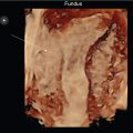
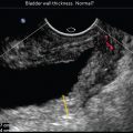
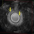
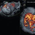
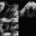
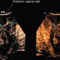
Stay updated, free articles. Join our Telegram channel

Full access? Get Clinical Tree


