Abstract
Radiofrequency receive-only coil arrays consist of a spatial arrangement of several small surface coil elements that record the magnetic resonance signal independently. This provides two major benefits: first, the sensitivity local to an individual element is increased due to the close coupling between the detector and tissue, thereby increasing the signal-to-noise ratio (SNR). Second, simultaneous reception from the coils enables parallel imaging reconstruction methods in which the acquisition time is decreased, thereby decreasing the amount of distortion caused by susceptibility artifacts. Challenges of spinal cord magnetic resonance imaging can therefore be alleviated by the use of highly sensitive receive coil arrays. In this chapter, we introduce some concepts, such as how to calculate the image SNR from array coils and how the geometric factor, or g -factor, affects parallel imaging reconstruction. We then review coils that have been developed for the human spinal cord at various magnetic fields (1.5–7.0 T) and show examples of advanced coil arrays for structural imaging, diffusion tensor imaging, and functional MRI of the spinal cord.
Keywords
Parallel imaging, Phased-array coils, Radiofrequency (RF) coils, Signal-to-noise ratio (SNR), Spinal cord
2.1.1
Introduction
Essential parts of a magnetic resonance imaging (MRI) system, radiofrequency (RF) coils or antennas are used to transmit and/or receive signal. Phased-array coils combine multiple small coil elements to transmit or receive signal using independent channels. Array coils were first described in a seminal paper by Roemer et al., and proof-of-concept was demonstrated in the spine. Since then, array coils have become the standard for multiple body parts in research and clinical MRI. The two main advantages are their increased sensitivity and the possibility of faster acquisition via parallel imaging. Several concepts related to array coils need to be understood to appreciate their full benefits and optimize their use, notably the B 1 magnetic field, the so-called geometric factor ( g -factor), and the signal-to-noise ratio (SNR).
This chapter will first introduce theoretical concepts related to RF coils, then will cover array coils and their advantages and limitations. We will review some of the existing array coils for human spinal cord imaging. We will then present design and building considerations, including safety aspects. Finally, we will look at how to evaluate transmit (Tx) and receive (Rx) coils (including the SNR and g -factor).
2.1.2
Coil Theory
The basic principle of RF coils is to create a B 1 magnetic field that rotates the magnetization of the nuclei (Tx coils) or to measure signal emitted by the resonating nuclei in the transverse plane (Rx coils). Both Tx and Rx coils are tuned to the Larmor frequency ( <SPAN role=presentation tabIndex=0 id=MathJax-Element-1-Frame class=MathJax style="POSITION: relative" data-mathml='ω’>ωω
ω
), at which particles can exchange energy. The Larmor frequency depends on the gyromagnetic ratio of the particle ( <SPAN role=presentation tabIndex=0 id=MathJax-Element-2-Frame class=MathJax style="POSITION: relative" data-mathml='γ’>γγ
γ
) and on the magnetic field strength they are submitted to ( B ), according to <SPAN role=presentation tabIndex=0 id=MathJax-Element-3-Frame class=MathJax style="POSITION: relative" data-mathml='ω=γB’>ω=γBω=γB
ω = γ B
. For example at 3 tesla, the Larmor frequency of water protons is about 127 MHz.
Coils consist of a set of inductive ( L ) and capacitive ( C ) elements that are chosen to make the coil resonate at the Larmor frequency, according to:
ω = 1 2 π L C
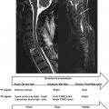
Coils are designed for transmitting, receiving, or performing both functions. The geometry of the coil can be optimized for its purpose. Typically, for transmitting coils, B 1 homogeneity should be high in order to obtain similar excitation (flip angle) over the region of interest. Conversely, for receiving, the ability to detect small magnetic flux generated by the resonating spins becomes more important than homogeneity, therefore sensitivity will be optimized. Thus, several coil geometries exist that achieve either good homogeneity or good sensitivity (sometimes both). Examples of volume and surface coils associated with their respective B 1 field are shown in Figure 2.1.1 . Typically, volume coils are used for transmission since they are made up of large elements and can achieve good B 1 homogeneity. Conversely, small surface coils are preferred for reception since they achieve high sensitivity. In standard MRI systems, the Tx coil is usually integrated into the scanner (also called the “body coil”), while the Rx coil is manually plugged into the system (either the patient’s table or the body of the scanner).

To understand how receive coils work, let’s consider a simple loop coil. According to Faraday’s law, the alternating magnetic field produced by the nearby rotating nuclei induces an alternating current in the loop. This principle is similar to the bicycle dynamo from which a current is generated via a rotating small magnet nearby a solenoid coil. The sensitivity of a single loop can be obtained from the Biot–Savart law. The larger the loop, the deeper it can capture signal from, but also the higher the amount of noise it will capture from the object scanned. Hence, optimal loop size should be designed depending on the desired penetration depth. For example, to achieve optimal sensitivity at 8 cm deep, a loop of approximately 8 cm is desired.
2.1.2.1
Q -Factor
The coil has resistive losses ( R ) within its conducting wires and various connections. The quality factor of the coil ( Q ) can be calculated as <SPAN role=presentation tabIndex=0 id=MathJax-Element-5-Frame class=MathJax style="POSITION: relative" data-mathml='Q=ωL/R’>Q=ωL/RQ=ωL/R
Q = ω L / R
. The higher the Q , the higher the SNR and hence the sensitivity of the coil. If the coil is loaded with biological tissue, some energy from the tissue is also captured by the coil via capacitive coupling. The fraction of loss dissipated in the tissue relative to the coil is evaluated by the so-called Q ratio, which is the ratio between Q while the coil is unloaded ( Q U ) and Q when the coil is loaded ( Q L ). Hence, Q U is necessarily bigger than Q L given that the body contributes to the measured noise. The goal when designing a coil is therefore to have Q U / Q L that is maximized, so that the coil is dominated by body noise with minimal electronic noise contribution.
2.1.3
Array Coils
2.1.3.1
Sensitivity
As mentioned in this chapter, a large loop can cover a large region but captures more thermal and physiological noise from the body. Contrariwise, a small loop captures less noise, as its sensitivity profile is restricted to a very small region close to the loop. The idea of having multiple small loops next to each other is to combine them in order to gain penetration in the sensitivity profile, while only capturing a small amount of noise coming from each individual coil element. This gives the rationale for designing coil arrays.
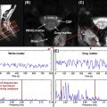
It is often mistakenly thought that in deep tissue, the sensitivity of phased-array coils with lots of small coils is poorer than that of coils with less but bigger elements. Although it is true that the penetration of each individual element of a phased-array coil is reduced, when combining several smaller elements into a phased-array coil, the sensitivity in deep tissue is similar to that of a coil with fewer elements. However, closer to the coil, the sensitivity of a phased-array coil is significantly higher. This was notably demonstrated using theoretical analyses and experiments. Figure 2.1.2 illustrates this point by comparing different coil arrangements.

2.1.3.2
Parallel Imaging
Another benefit of array coils—in addition to higher sensitivity—is that simultaneous reception from the coils enables parallel imaging reconstruction methods. Parallel acquisition consists of skipping lines of k -space in the phase-encoding direction, which reduces the effective echo spacing, resulting in less image distortions in echo planar imaging (EPI) sequences (also see Chapter 2.3 ). The signal recorded by each independent coil is then used to reconstruct an unaliased image by either filling missing lines of k -space (the SMASH or GRAPPA methods) or unaliasing pixels in the image domain (the SENSE method). The performance of the coil regarding acceleration capabilities is therefore dictated by the geometry of the coil, or the so-called g -factor. The lower the g -factor, the better the coil performance is with respect to parallel acquisition, with the lowest g -factor being 1.
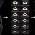
To qualitatively assess a coil capability for parallel imaging, one first needs to consider what will be the typical direction for phase encoding (i.e., direction of acceleration). For example, if a coil consists of 16 elements disposed around a cylinder (see Figure 2.1.3 (A) ), the g -factor will be low in the X and Y directions, while it will be high along the Z direction. This means that the coil will perform better when acceleration occurs along the X or Y direction. In contrast, Figure 2.1.3 (B) shows an arrangement that favors acceleration in the Z direction but not in the X or Y direction. Hence, optimal design of a coil should take into consideration acceleration capabilities. That is, if spinal cord imaging is typically performed with phase encoding in the antero-posterior direction, there should be enough individual coil coverage along this direction in order to reduce the g -factor. If this were not the case, reconstruction artifacts would occur and SNR would be substantially reduced (SNR is inversely proportional to the g -factor, as described later in this chapter). For a comprehensive review on parallel imaging, the reader is referred to Ref. .
a With some vendors, it is possible to manually set the number of channels used with particular coils; for example, the spine array matrix can be used as single (CP), dual , or triple mode . For the highest parallel imaging capabilities, triple mode should be set.
- •
Twelve-channel (12-ch) head coil (upper cervical): maximum of 3× acceleration along the antero-posterior (A-P) or right-left (R-L) direction
- •
4-ch neck coil (cervical): maximum of 2× acceleration along the A-P or R-L direction
- •
24-ch spine array (thoracic and lumbar): maximum of 2× acceleration along the A-P or R-L direction, 3× acceleration along the superior-inferior (S-I) direction

2.1.3.3
Design and Building Considerations
2.1.3.3.1
Geometry
When designing RF coils, some key aspects need to be considered. One of the most important aspects is that the Tx coil should have excellent B 1 homogeneity, while the Rx coil should have excellent sensitivity. Hence, for Rx coils, elements need to be close to the region of interest (e.g., the spinal cord). A morphological model in combination with B 1 field simulations are helpful for designing the final shape of the coil former and the layout of each element.
For the cervical spinal cord, the geometry of the body allows elements to be placed around the neck to improve sensitivity. In typical state-of-the-art clinical coils, the head coil is compatible with the spine array and an anterior neck coil, and all elements can be selected simultaneously for imaging the head and spinal cord. Additionally, commercially available head and cervical arrays are typically designed for comfort and to be used with nearly 100% of the population, and hence they are generally not made to fit as tightly to the body as might be desired in a research setting where sensitivity is the primary concern.
For the thoracic, lumbar, and sacral spinal cord, elements need to be placed posteriorly to the body. Placing elements anteriorly could be considered, given the almost central location of the spinal cord in the A-P direction. An advantage of placing elements anteriorly is to lower the g -factor in the A-P direction, enabling at least twofold acceleration in this direction, which is difficult to achieve with coils placed only posteriorly. Of course, superior-inferior or right-left acceleration is still possible with phased-array coils placed posteriorly, although these phase-encoding directions are less commonly used with spinal cord EPI. One disadvantage of having elements anteriorly is that signal from the heart (for thoracic) and/or chest (for thoraco-lumbar) would be picked up. These regions are prone to severe motion artifacts and therefore can result in severe ghosting artifacts that can overlap the spinal cord. Another disadvantage of placing elements anteriorly is that using reduced field-of-view (FOV) techniques requires further saturation (or two-dimensional selective RF excitation) to null the signal coming anteriorly from the cord. If no anterior coil is used, very little signal is picked up from regions anterior to the cord, making it easier to apply reduced FOV techniques.
An original design of a thoraco-lumbar 7 T phased-array coil has been proposed by Vossen et al. There, the Tx coil is placed anteriorly, and the Rx coil posteriorly. One advantage of doing so is that the total power deposited in the body is lower if the RF energy is transmitted through the lungs from the anterior side to the centrally located spinal cord, compared to the case where the Tx coil is placed on the posterior side of the body, where the RF field must propagate through a large muscle mass with high conductivity.
2.1.3.4
Review of Array Coils for the Spinal Cord
Although receive arrays were originally developed and demonstrated for spinal cord imaging, most highly parallel detectors (≥32 elements) have focused on being developed for the brain and heart.
For 1.5 and 3 T systems, several array designs have been proposed for the spinal cord. These include arrays designed for full coverage of the spine, with up to 24 channels, and those designed specifically for the cervical spine, with up to 16 channels. Given that these designs are typically not compatible with manufacturers’ head coils, recent designs have included the brain for full coverage of the head and cervical spinal cord, using for example 32 elements or 64 elements.
For 7 T systems, mostly Tx and Rx coils have been developed, including 4-ch and 6-ch coils using nonoverlapping elements, an 8-ch coil (two rows of four overlapped elements), and a 4-ch coil. Using the latter coil, the SNR benefit of 7 T over 3 T was notably shown by comparing data acquired in the same subject. At 7 T, separate Tx and Rx coils have also been designed. For example, a 2-ch Tx was combined with an 8-ch Rx coil (one row of overlapped elements for a total length of 90 cm), where simulations were used to find the best location for excitation (anteriorly versus posteriorly). In another work, a 4-ch Tx was combined with a 19-ch Rx coil. In this design, Zhao et al. used the 4-ch Tx coil with a single-channel Tx mode where the Tx signal was split using a butler matrix (with the 45° phase incrementally added in each element to optimize B 1 homogeneity). More recently, a 30-ch Rx coil demonstrated high-quality magnetic resonance spectroscopy in the spinal cord.
Multiple groups opted for a flat design. These coils are easier to build, and they can be used for any level of the spine. One disadvantage, however, is that they are not optimized for the cervical region, where elements could also be placed around the neck, thereby potentially increasing the sensitivity and g -factor. Picture samples of spine coils for 3 T and 7 T systems are shown in Figure 2.1.4 .

2.1.4
Evaluation of Tx Array Coils
2.1.4.1
SAR Calculation
For Tx coils, the main safety assessment is the energy deposited to the tissue during excitation. It is measured by the specific absorption rate (SAR), defined as the RF power absorbed per unit of mass of an object (in W/kg). Limits of maximum SAR are fixed by country authorities and cannot exceed certain values. For example, in the United States, during normal operation mode over a period of 6 min, the maximum SAR allowed is 4 W/kg (whole body average over 15 min) or 8 W/kg (in the head or trunk over 10 min).
Hence, when building a coil, SAR is calculated as a function of the voltage submitted to the coil, in order to get an estimate of the maximum voltage that is allowed. To predict SAR from a particular design, electromagnetic simulations are required. Using finite-difference time domain (FDTD) or finite element method (FEM) modeling of Maxwell’s equation, and using models of human tissue, it is possible to predict conductivity. Simulation software packages include Remcom, Semcad and HFSS. Figure 2.1.5 shows an example of 4-ch Tx coil simulations for estimating the B 1 field, as well as the SAR in a human model. Simulations, however, can be quite computer-intensive and results are very sensitive to the input parameters (geometry and placement of the coils, modeling of the gradient cylinder, choice of gridding, and choice of human model). Hence, it is often the case that SAR simulations can be off compared to the real situation, given the inaccuracies of simulations and the nonperfect reproduction of the design on the bench. For this reason, it is advisable to perform additional temperature tests on a phantom and be conservative on the maximum voltage allowed.

2.1.5
Evaluation of Rx Array Coils
2.1.5.1
Image SNR
Although SNR can easily be calculated by dividing the mean signal intensity by the standard deviation in the image background, this method is no more correct when using phased-array coils, given that both the statistical and the spatial distribution of noise are different than that with a single-channel coil. For example, the sum-of-squares reconstruction changes the statistical distribution of background noise, and some filters applied during reconstruction can influence the spatial distribution of the noise.
Hence, for quantifying SNR in a phased-array coil, other methods should be employed based on the true calculation of noise in each voxel. One method is to acquire a proton density weighted gradient echo image, then measure noise covariance in each channel using the same sequence without RF excitation. Given a signal vector S (a vector of image intensities at a given pixel across all coils), with S H being the Hermitian transpose of S, the image SNR for the root-sum-of-squares (rSoS) combination image can be expressed as:
SN R rSoS = S H S S H Ψ S
Related posts:

Stay updated, free articles. Join our Telegram channel

Full access? Get Clinical Tree


