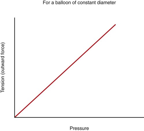
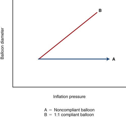
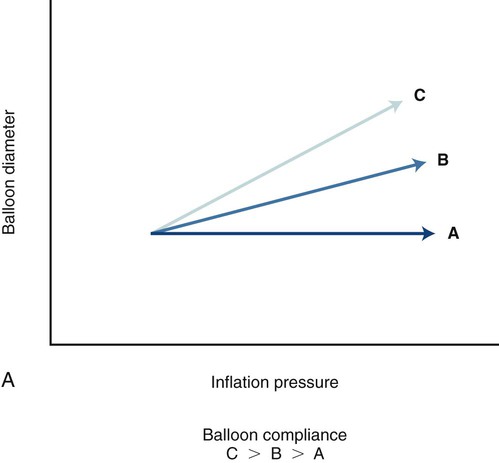
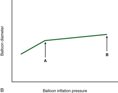
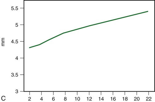
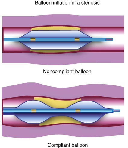
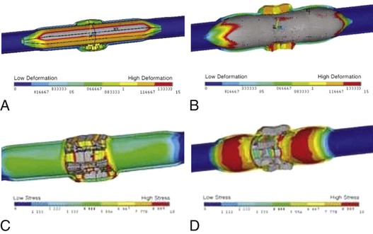
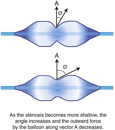
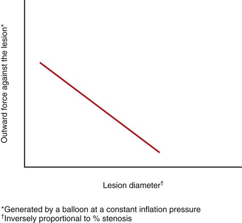
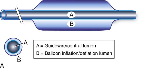
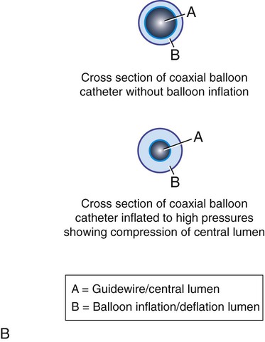
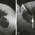
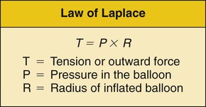
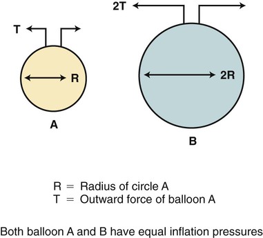
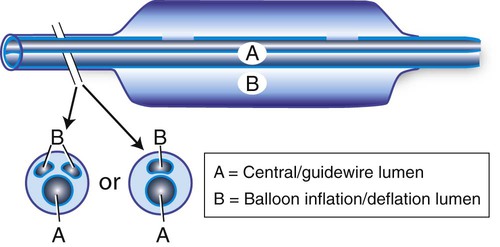
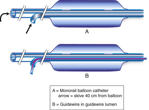
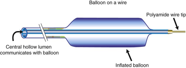
Chapter 5 Shawn N. Sarin, Wael E.A. Saad, David Nicholson, Ulku C. Turba, J. Fritz Angle, Klaus D. Hagspiel, Michael D. Dake and Alan H. Matsumoto Although Dotter and Judkins first described percutaneous transluminal angioplasty (PTA) in 1964,1 use of the procedure did not gain momentum until 1976, when Gruentzig2 described his double-lumen balloon catheter. The Gruentzig balloon catheter incorporated balloon material that was relatively noncompliant and mounted on small catheters (7F-8F) that could be advanced coaxially over a guidewire. Since its introduction, the design of balloon catheters has improved as technology has evolved. It is important for one to understand the physical principles that govern the effects of balloon dilation.3,4 Dilating force is the outward force exerted against a luminal stenosis. It is dependent on balloon diameter, the balloon’s inflation pressure, compliance of the balloon material, balloon length, and the degree of stenosis.3,4 The law of Laplace states that the force or tension (T) exerted on the wall of the inflated balloon is directly proportional to the pressure (P) within the balloon and the radius (R) of the balloon (T = P × R) (Fig. e5-1). Thus, a balloon with twice the radius of a smaller balloon will exert twice the tension on the wall of a balloon for a given inflation pressure. If the diameter of the balloon is kept constant, the tension on the wall of the balloon will increase linearly with increases in inflation pressure (Fig. e5-2). Because the tension on the balloon wall translates into dilating force, the dilating force generated by a balloon is directly proportional to the balloon’s diameter and inflation pressure. Therefore, larger balloons will require less pressure than smaller balloons to generate substantial dilating force (Fig. e5-3). Similarly, larger vessels such as the abdominal aorta or the common iliac arteries require less pressure to dilate and rupture. The pressure within an angioplasty balloon is universally measured in atmospheres (atm). An atmosphere is a unit of pressure that will support a column of mercury 760 mm high at sea level and 0°C. Compliance is a measure of how much a balloon will stretch beyond a predetermined diameter when a force is applied to it (Fig. e5-4). All balloon materials are elastic. Consequently, all balloons have some inherent degree of compliance. A completely noncompliant balloon will not stretch beyond a predetermined diameter—despite increases in inflation pressure—and will maintain its profile and shape with repeated inflations (Fig. e5-5, A–C). The pressure that would cause permanent deformation of a noncompliant balloon (tensile strength) would approximate the pressure required to rupture the balloon (yield strength). If the balloon material is compliant, increases in inflation pressure will result in further balloon expansion, especially in areas of lower resistance (i.e., in the adjacent normal vessel lumen rather than in the area of stenosis). Balloon compliance prevents the dilating force from being concentrated in the region of the stenosis (Fig. e5-6). Therefore, when compared with a relatively compliant balloon, a noncompliant balloon will have a more predictable diameter at various inflation pressures and provide a greater amount of dilating force in a lesion. As balloon pressure is increased, semicompliant balloons continue to expand in diameter. When inflated in a resistant lesion, the balloon “hourglasses” or “dog bones” (see Fig. e5-6), thereby creating stress injury and deformation of adjacent normal vessel segments. Based on a vessel wall displacement model using a noncompliant polyethylene terephthalate (PET) balloon and a semicompliant nylon balloon, both inflated to their respective rated burst pressure (RBP) and matched to the internal diameter of the vessel model, greater vessel deformation is seen on either side of the lesion with the semicompliant balloon. A simulation stress model shows that in a typical 8-mm vessel, a semicompliant balloon produces large variations in wall stress in the adjacent nonstenotic segments of the vessel, whereas vessel wall stress remains relatively constant with inflation of a noncompliant balloon (Fig. e5-7). A longer lesion has a larger total area of stenosis than a shorter one does. As a result, the dilating force created by a balloon is greater in a longer lesion. In addition, the dilating force generated in a lesion is directly proportional to the degree of stenosis for a fixed balloon diameter and inflation pressure. As such, more dilating force will be generated in a tight, high-grade stenosis than in a shallow stenosis (Fig. e5-8). This principle is governed by the so-called clothesline effect. That is, the radial force vector generated by a balloon in a stenosis is greatest when the balloon has more of a “waist” on it (Fig. e5-9). This outward force vector decreases as the waist on the balloon diminishes. Therefore, continuing to increase balloon inflation pressure to eliminate a minimal residual waist will result in relatively small incremental changes in dilating force and is more likely to rupture the balloon. In this setting, low-profile “high-pressure” balloons offer an advantage over low-pressure balloon catheters. In the past, if a residual waist could not be resolved, the procedure was either terminated or a larger balloon was used. With the use of a larger-diameter balloon, more dilating force can be generated, but the risk of rupturing the vessel or creating a dissection “flap” is also increased. Most balloons are currently made of PET or nylon derivates (Table 5-1). In the past, other plastic polymers such as polyvinyl chloride (PVC), polyethylene (PE), or reinforced polyurethane have been used.5–8 PVC, the material that was used in the original Gruentzig balloon catheter,2 shows a moderate degree of compliance even at nominal balloon inflation pressures. In vitro studies have shown that balloon diameter can increase from the first to the second inflation by 5% to 17% and by as much as 33% after six inflations.5,6 PVC balloons also deform and elongate with increasing inflation pressure.7 They rupture at significantly lower inflation pressures than balloons constructed from other materials.3,5 Therefore, PVC has largely been abandoned as a balloon material. TABLE 5-1 Characteristics of Balloon Materials EtO, Ethylene oxide gas; PE, polyethylene; PET, polyethylene terephthalate; PVC, polyvinyl chloride. PE is an inert plastic that contains no additives. PE balloons are less compliant than those made from PVC. They show only minor increases in diameter (<2%) and minimal deformity when inflated to suggested working pressures,5,7 although lower-profile PE balloon catheters (made with thinner PE) are slightly more compliant. PE balloons generate almost twice as much dilating force as the same size PVC balloon and have higher burst pressures than PVC balloons.3,6 PE balloons are more scratch resistant than PET balloons in that they tend to perforate less often in calcified lesions and stents. The Gruentzig balloon was a coaxially designed double-lumen catheter (Fig. e5-10, A and B).2 The inner catheter was surrounded by a thin tube of PVC with an expandable end (the balloon). The inner and outer catheters were bonded together with heat. This coaxial design became less popular because of the suboptimal compliance characteristics of PVC and concern for overexpansion of the outer lumen at higher inflation pressures and resultant compression of the inner lumen.5,7 In addition, with deflation, the overstretched outer catheter sleeve can become redundant and “accordion” and “bunch up” when attempts are made to withdraw the catheter. A potential advantage of a coaxial catheter design is that balloon inflation and deflation times are faster than with comparably sized double-lumen balloon catheters. By having the guidewire lumen central in location and concentrically oriented, longitudinal pushability and the ability of the catheter to track over a guidewire are improved. However, catheters of this design are now limited to small vessel balloon catheters, where according to the law of Laplace, compliance is less of a problem. Some companies have released larger balloon catheters with a coaxial design whose shafts are made of materials less compliant than PVC. Most modern balloon catheters are true double- or triple-lumen catheters (Fig. e5-11). The shaft is usually composed of a polyester, PE, nylon, or polyamide derivative. The balloon is attached to the catheter shaft by some adhesive or thermal bonding, or both. The outer smaller lumen, which communicates with the side port, is used to inflate and deflate the balloon. The shape of the lumen that communicates with the balloon varies and may be round, crescenteric, or a half circle. Inflation and deflation characteristics of the balloon may vary depending on the size and shape of the second or third lumen. With the wide variety of guide catheters and sheaths that have become available, the rapid-exchange (monorail) catheter system has become one of the most popular balloon catheter designs. This system has an exit port for the guidewire (termed the skive) approximately 40 cm proximal to the balloon (Fig. e5-12). The proximal port of the catheter communicates with the balloon. A stiffening wire is often incorporated into the shaft of the catheter to improve catheter pushability. A major advantage of this system is that there is no need to use exchange-length guidewires despite considerable catheter length. Another advantage is that the large lumen communicating with the balloon makes balloon inflation and deflation times rapid. Disadvantages associated with a monorail design include absence of a port through which to inject contrast and the possibility that the balloon catheter may not track as well through tight lesions or tortuous vessels. However, most monorail balloons are used through guide catheters or sheaths, making trackability less of an issue. Another balloon catheter design popularized by Charles J. Tegtmeyer in the mid-1980s9 is the “balloon on a wire” (Fig. e5-13). The design consisted of a polymer-coated, braided, stainless steel guidewire with a hollow core that communicated with a PET balloon. The segment immediately adjacent to the balloon was constructed in a fashion that made it more flexible than the proximal portion of the guidewire shaft. Distal to the balloon, there was a variable-length platinum or polyamide 0.018- to 0.022-inch wire tip. The intent of this balloon design was to create a low-profile, torquable balloon dilation system that was used with a guide catheter. However, as balloon catheter technology progressed, this design was supplanted by coaxial and monorail 0.014- to 0.018-inch systems.
Balloon Catheters
Physical Principles of Balloon Dilation
Balloon Materials
Materials
Tensile Strength
Compliance (Relative)
Stiffness
Profile
Maximum Rated Pressure (atm)
Sterilization
PET
High
Low
High
Low
20
EtO or radiation
Nylon
Medium-high
Medium
Low
Low
16
EtO
PE
Medium
Medium
Low
Medium
10
EtO or radiation
PET/PE fibers and Pebax
Very high
Very low
High
Medium
30
EtO
PVC
Low
High
Medium
High
6-8
Radiation
NyBax
High
High
Low
Low
24
EtO or Radiation

Catheter Design
![]()
Stay updated, free articles. Join our Telegram channel

Full access? Get Clinical Tree


Radiology Key
Fastest Radiology Insight Engine

