It is the small differences in Z between different soft tissues which are utilized in ultrasonography.
It is important to distinguish the propagating acoustic wave phenomenon from the coherent oscillatory motions of the individual particles in the material. The maximum velocity of the particles, as they pass their equilibrium positions, relates to the energy transported by the acoustic wave through the material. At the energy inputs applied in ultrasonography, the maximum particle velocities in soft tissues are only 3–4 cm × sec−1 or less, and the excursion to either side of their equilibrium positions, denoted the elongation, is in the order of 2 nm (nanometer) or less, not to be confused with the wavelength (λ) of the sound.
The Ultrasound Transducer
The source of ultrasound for diagnostic imaging is the piezoelectric ultrasound transducer (Figure 44). The key component of this assembly is a disc of a special ceramic material made up of orderly aligned molecules that have the property of being electrical dipoles. A thin layer of electrically conducting metal has been plated onto both sides of the disc, so that an electrical field (in the order of 150 volts) can be set up across the disc, which is often termed the “crystal”. In response to an electrical field the molecular dipoles realign, and the disc consequently changes its thickness. When a high-frequency alternating voltage is applied, the disc oscillates and these oscillations become particularly forceful and uniform at a particular frequency, the resonance frequency. When the voltage is turned off, the crystal continues to oscillate at its resonance frequency, which is determined by the thickness of the disc. The “backing material” in the transducer assembly quickly damps this “after ringing”. It is essential that the ultrasound impulse lengths are extremely short (in the order of 1 μsec), because the axial (“depth”) resolution decreases for increasing spatial pulse length. Reduction of the wave length (i.e. increased frequency) also reduces the spatial pulse length and improves resolution.
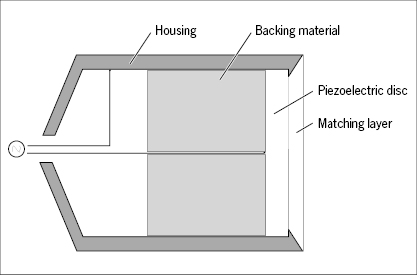
The transducer is covered by a thin “matching layer” of a material with an acoustic impedance in between that of the ceramic disc and that of the skin. When the transducer is held against the skin the acoustic impedance is further improved by a watery gel spread in advance over the skin.
The piezoelectric transducer functions also in the reverse direction as receiver of ultrasound echoes. The receiving period is much longer (some hundred μsec) than the transmission period to give time for capture of echoes stemming from deeply located structures. When the receiving (“listening”) transducer is hit by incoming ultrasound waves the disc becomes slightly deformed and electrical potentials in the order of 2 μvolts are set up across the disc. These electrical signals are the ones used to construct the image.
For simplicity a scanner with only one transducer element is considered first. The ceramic disc of the transducer acts as a vibrating piston producing a “beam” of ultrasound waves (Figure 45). If the disc is circular and plane the beam becomes almost rod-shaped out to a certain distance from the disc, the “near field” or Fresnel zone, and the beam intensity falls off steeply along the edge of the beam. This is the useful part of the beam. At a certain distance from the crystal the beam spreads out in a cone, the “far field” or Fraunhofer zone, which is not useful for imaging. The physics governing the shape of the beam is rather complex, but depends primarily on the diameter of the crystal and the sound frequency. The disc may be concave shaped or an acoustic lens may be inserted to make the beam converge towards a focus, but this reduces the length of the useful field (Figure 45). The lateral resolution depends on the width of the beam. Focusing improves resolution, but reduces the thickness of tissue imaged.

It should be noted that when the transducer is used for imaging, the waves are sent off in very short “trains” followed by a pause where the transducer “listens” to echoes. The spatial length of a train is 2 mm or less, but follows the path of the continuous beam as a propagating cross-section of it.
Interactions of Ultrasound with Matter
At all ultrasound frequencies and intensities applied in diagnostic imaging, three types of interactions are relevant: absorption, reflection, and diffuse scatter, all contributing to attenuation of the ultrasound beam intensity. Additionally, refraction and diffraction phenomena take place, but they are of minor practical significance. At beam intensities much higher and of longer duration than those used for imaging, various destructive effects take place in the tissue, not to be elaborated on here.
Absorption
Absorption of ultrasound in tissues means transfer of kinetic energy from the coherent particle oscillations into disordered particle motions, that is, heat, caused by internal friction between the constituent molecules of the tissue. Absorption is the dominant contributor to ultrasound beam attenuation. The intensity of the beam decays exponentially with distance and is therefore conveniently expressed in decibels (dB). Additionally, absorption increases linearly with the frequency in soft tissues. On average the absorption mounts to 1 db cm−1 MHz−1. Thus, at a depth of 10 cm the intensity of a 5 MHz beam has been reduced by 50 dB, that is, a 100 000-fold reduction.
Considering that an echo from this depth will have to travel another 10 cm back to the transducer, the signal will have decayed by about 100 dB relative to an echo received from a structure superficially in the skin. A signal reduced this much is virtually useless. Therefore for imaging of deep structures, for example in the abdomen, lower frequencies are used, but this is at the expense of resolution. Absorption in urine is significantly lower than in soft tissues. A filled bladder may therefore be utilized as an “acoustic window” to pelvic viscera.
Reflection
When the propagating ultrasound wave front encounters an interface between two tissues of different acoustic impedance, part of the energy is reflected as an echo. If the acoustic impedances of the two tissues are identical, no echo is produced. If the difference is very large, as between soft tissue and bone or air, virtually all the wave energy is reflected, producing a strong echo and an “acoustic shadow” behind the bone or an air-filled organ. This effect makes it impossible to image the adult brain through the skull, while a neonatal brain may be imaged excellently through the fontanelles. It also makes it impossible to image lungs and air-filled intestines.
Stay updated, free articles. Join our Telegram channel

Full access? Get Clinical Tree


