The propagation velocity (c) of electromagnetic waves is constant (in vacuo): 3 × 10¹⁷ nm × sec−1, and relates to wavelength (λ) and frequency (ν) by: c = λ × ν.
Electromagnetic waves are emitted as discrete quanta of energy (photons). The energy (E) of a photon relates to its frequency (ν) by: 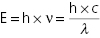 , where h is Planck’s constant. If energy is expressed in keV and wavelength (λ) in nanometers, the relation becomes:
  .
.
One electron volt (eV) is the energy acquired by an electron accelerated through a gradient of one volt. 1000 eV = 1 keV.
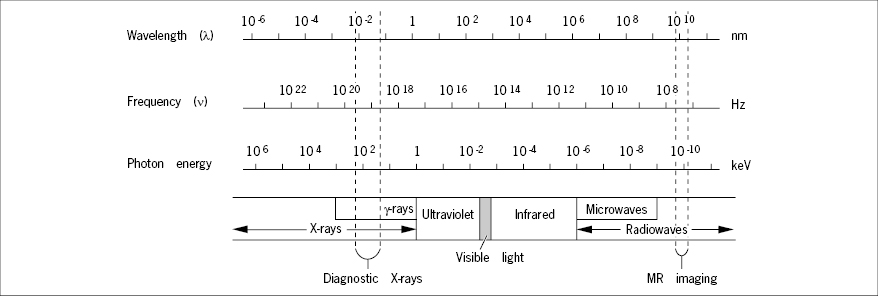
The X-Ray Tube
The source of X-rays for diagnostic imaging is the X-ray tube (Figure 2) in which a narrow beam of electrons, emitted from an electrically heated tungsten filament (the cathode), is accelerated in vacuo and focused electrostatically to impinge the target anode that emits a small fraction (0.2–2%) of the incident electron energy as X-rays. The rest of the energy dissipates as heat in the anode, which usually is made from a tungsten alloy with high thermal stability, shaped as a disc and rotating at high speed to spread the thermal load evenly over a large area.
Details of circuitry are not given.
- 1: Cathode filament
- 2: Electron beam
- 3: Rotating anode
- 4: Anode motor drive
- 5: Vacuum tube
- 6: Lead shield
- 7: Window
- 8: Central ray
The energy (wavelength) of the X-rays generated by the tube is primarily controlled by adjustment of the electrical potential difference between the cathode and the anode, the accelerating voltage. The high voltage is generated by rectification and high voltage transformation of common 50–60 Hz alternating current (AC) which has been converted up to some 50,000 Hz AC. Evening-out is incomplete and the high voltage is rippled. The ripple is expressed as the difference between the peak and the minimum voltage in per cent of the peak voltage and mounts to 5–10% in most high voltage generators. The high voltage setting of an X-ray unit usually refers to the peak voltage and is denoted kVp to indicate this fact.
The intensity of X-rays produced by the tube at a given voltage setting is determined by the number of electrons hitting the anode, that is, the current carried by the electrons through the vacuum from the cathode to the anode, termed the beam (or tube) current and expressed in milliamperes (mA). For accelerating voltages above some 40 kV (the saturation voltage), the beam current is largely determined by the cathode filament temperature only and can be regulated by the filament heating current supply.
The quantity (dose) of X-rays delivered by the tube is proportional to the time the beam current flows and is conveniently expressed as milliampere seconds (mAs).
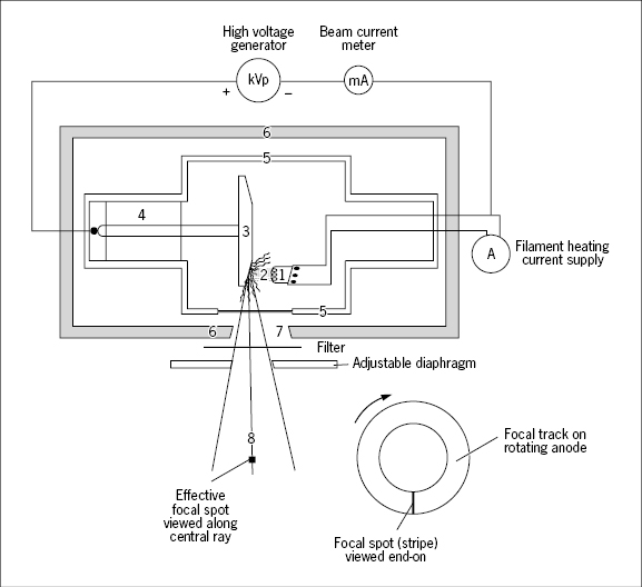
The X-ray photons emitted by the anode distribute with varying intensity over a spectrum with a maximum set by the peak accelerating voltage of the tube. Thus, the X-ray beam is polychromatic. Even if the accelerating voltage is constant (not rippled) the beam is still highly polychromatic due to the nature of the process by which X-rays are generated at the anode (“bremsstrahlung”), not to be elaborated here.
Photons with energies below some 20 keV are useless for most radiography purposes because they cannot penetrate the body parts examined. Still they are harmful because their energy is absorbed superficially in the irradiated tissue, especially the skin. Insertion of thin aluminum or copper plates, filters, in the path of the X-ray beam removes these unwanted low energy photons (Figure 3). The mean photon energy thereby increases; the beam is said to be hardened. Mammography employs the lowest photon energies in diagnostic X-ray imaging, around 25–30 keV, in order to optimize detection of the very small differences in X-ray absorption between normal and cancerous tissue.
Even the unfiltered beam has been “filtered” by passage through the wall of the X-ray tube whereby the lowest energies have been rejected. Additional filtering lowers the overall intensity, but increases the mean photon energy.
The X-ray tube is surrounded by a lead shield with a window that permits passage of the X-rays. The size and shape of the window, the aperture, can be varied by means of adjustable diaphragms (Figure 2). The X-rays radiate from the tube as a diverging bundle originating from the area on the anode hit by the electron beam, the “focus”, and limited by the tube exit aperture. The axis of the bundle is called the central ray, and the focus viewed along this axis is called the effective focal spot. The smaller this spot, the better the resolution in the radiograph. They are mostly in the order of 1 mm2 or less; in mammography down to 0.1 mm2 which allows detection of the tiny calcium deposits often found in malignant mammary tumors.
The X-ray beam should always be restricted by the diaphragms to illuminate the minimally required area of the body to minimize radiation exposure. This adjustment is called collimation.
Interactions of X-Rays with Matter
At the X-ray energies applied in diagnostic imaging, three types of interaction are to be considered: elastic scatter, the photoelectric effect, and inelastic (Compton) scatter.
Elastic scatter is an interaction whereby photons undergo a change of direction without loss of energy. This type of scatter takes place at all diagnostically relevant photon energies, but accounts for only a few per cent of the total scatter.
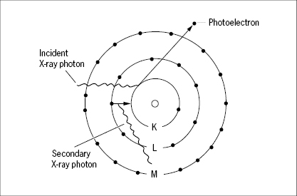
The photoelectric effect (Figure 4) is an interaction in which the incident X-ray photon delivers all of its energy to an atom which in turn releases this energy in the form of an electron, a photoelectron, which is ejected from one of the inner electron shells of the atom at high speed. An electron from one of the outer shells soon “falls in” to fill the vacancy, and energy is concomitantly released in the form of a new X-ray photon, emitted in a random direction and with an energy that is characteristic for the particular element. This secondary photon is of lower energy than the exiting photon. It may emerge as secondary radiation from the object, but is mostly absorbed by new interactions. The atom is left ionized, and the released electron collides with other atoms and causes a large number of secondary ionizations. The photoelectric effect is strong when the incident photon energy is just moderately higher than the binding energy of an inner shell electron. Only the two electrons in the innermost shell, the K-shell, have binding energies sufficiently high to engage in photoelectric interactions within the diagnostically relevant X-ray energy range. The photon energy, just sufficient to release a photoelectron from the K-shell, is denoted a K-edge, because the X-ray attenuation increases steeply as a threshold phenomenon at this energy level (Figure 5). The K-edges have characteristic values for different elements (Table 1). In soft tissues composed of lighter elements (C, N, O), photoelectric attenuation becomes quantitatively unimportant at photon energies above some 35 keV. Because the binding energy of K-shell electrons is higher for higher elements (such as calcium), the photoelectric effect remains quantitatively important for bone imaging up to some 50 keV. Barium and iodine have their K-edges at 37 keV and 33 keV, respectively. It is these high K-edges that are utilized when barium and iodine are used in contrast media.
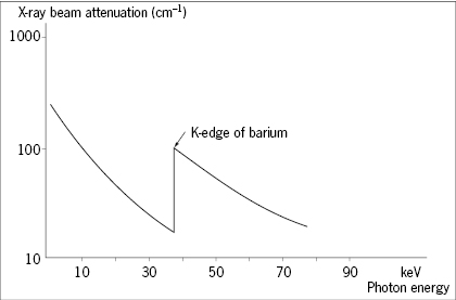
X-ray absorption increases steeply at photon energies equal to the binding energy of the K-shell electrons of an element, a so-called K-edge.
| Element | K-edge (keV) |
|---|---|
| Carbon | 0.3 |
| Nitrogen | 0.4 |
| Oxygen | 0.5 |
| Phosphorus | 2.1 |
| Calcium | 4.0 |
| Iodine | 33.2 |
| Barium | 37.4 |
| Lead | 88.1 |
| Iron | 7.1 |
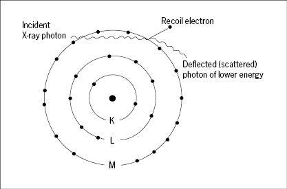
The inelastic (Compton) scatter (Figure 6) results from interaction of X-ray photons with outer shell electrons which are ejected (recoil electrons) to leave the atom ionized, while the incident photon proceeds with reduced energy and a change of direction. An X-ray photon may engage in several such events of inelastic scatter on its path through an object, eventually giving up all of its energy, that is, it becomes absorbed in the tissue. Compton scatter accounts for most of the scatter in diagnostic radiology. It depends primarily on the number of electrons per unit volume of tissue, and this in turn correlates almost linearly with the mass density of the tissues. It is independent of atomic number, and this is why the contrast of bone relative to soft tissues decreases at higher X-ray energies, where the photoelectric effect disappears.
Both the photoelectric effect and inelastic scatter result in a loss of electrons from atoms. This may cause the breakage of chemical bonds, and because the ionized atoms (notably those of C, N and O) are chemically highly reactive, new chemical bonds are established that are alien to the tissue. It is the X-rays’ ability to cause ionizations that includes them in the family of ionizing radiation, and it is these ionizations and their derived chemical reactions that cause the biological damage of such radiation.
The differential ability of various tissues to scatter and absorb X-ray photons, no matter by which mechanisms, is given by their linear attenuation coefficient (cm−1) which expresses the fractional reduction in beam intensity along a linear beam path after passage through one centimeter of the tissue. The linear attenuation coefficient of a given tissue varies with the X-ray photon energy, being high for lower energies where the photoelectric effect prevails and leveling off for higher energies where Compton scatter dominates, and hence the mass density rather than the atomic composition of the tissue becomes the prime determinant of attenuation (Figures 7 and 8).
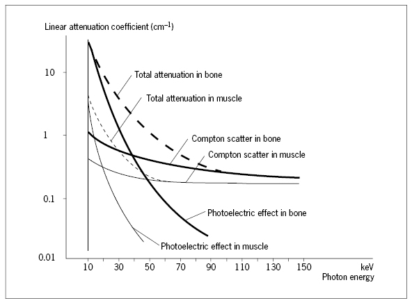
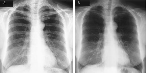
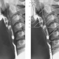
Image (A) is recorded with a voltage setting at 50 kVp, (B) at 150 kVp. The lower beam energy in (A) yields higher contrast between bone and soft tissues, because of the contribution of photoelectric interactions in bone imaging at low kVp.
Conventional Imaging with X-rays
The basic set-up for conventional imaging with X-rays is very simple (Figure 9). The X-ray tube focal spot acts as a point source. The body part examined is composed of structural elements with different transparencies (attenuation coefficients) for X-rays, and the image appears as a 2D projection of the 3D object, much like a shadow figure, following the simple geometric rule of central projection. Thus, X-ray imaging is very different from optical imaging which implies a distinct focal plane in the object and a distinct image plane.
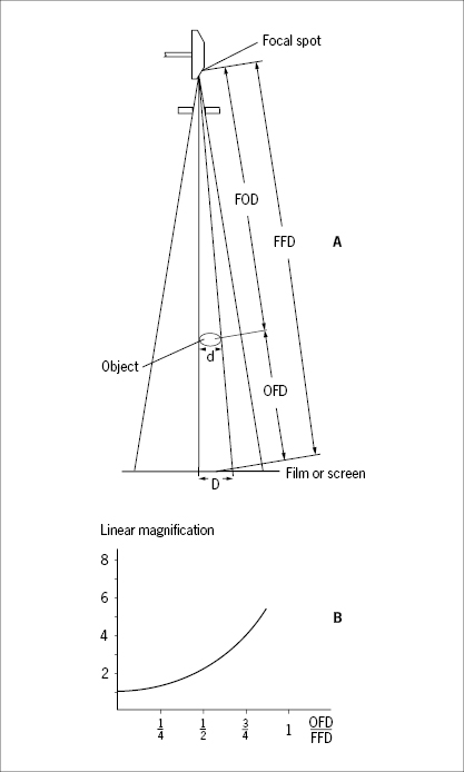
- Linear magnification
- Magnification as a function of the object-to-film distance (OFD) relative to the focus-to-film distance (FFD).
The bundle of collimated and filtered X-rays leaving a correctly adjusted tube has approximately the same intensity throughout a cross-section of the bundle. Accordingly, the intensity decreases proportionately as the square of the distance from the focal spot. The streams of linearly propagating X-ray photons (“rays”) are variously attenuated by scatter and absorption along different linear paths through the object, depending on the thickness, the density and the elemental composition of the structural details passed. The emerging bundle of X-rays, modulated during passage through the object, conveys information in the form of variations in beam intensity within a cross-section of the bundle. This modulated bundle of X-rays is sometimes referred to as the aerial image, which may be recorded on a photographic film, a fluorescent screen or a digital image recorder inserted anywhere across the bundle.
Imaging Geometry
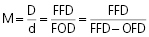
It follows from the principle of central projection that the image is always magnified. The magnification increases when the object-to-film distance (OFD) is increased, and the magnification decreases when the focus-to-object distance (FOD) is increased (Figure 9). This implies that relative dimensional distortions are inherent in the image because structural details located closer to the focus are magnified more than details from a more remote location within the object (Figure 9B). This effect becomes more pronounced the thicker the object is relative to the focus-to-film distance. Inherent in the imaging principle is also that structural elements along the same linear path are all superimposed, and information on their relative depth in the object is not contained in the image.
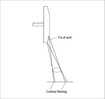
The contour sharpness of an imaged object (e.g. a trabecula of bone) is highly dependent on the size of the focal spot as well as the OFD relative to the FOD; the shorter the OFD and the longer the FOD, the sharper the contour. The width of the contour blurring, the penumbra, is equal to the projected image of the focal spot through a tiny pinhole at the position of the object (Figure 10). The shorter the FOD and the longer the OFD, the wider the penumbra becomes.
Scattered Radiation
The interaction of the incident X-rays with the object causes random scatter of X-ray photons. This scatter is, on the one hand, a major contributor to the linear ray attenuation on which X-ray imaging is based, but is on the other hand a nuisance if the scattered photons reach the image recorder (film) because they spread randomly as noise over the field and impair image contrast and resolution. Thus, preventing scattered X-rays from reaching the film is a major concern in radiology. One or more of the following measures are employed to this end:
Stay updated, free articles. Join our Telegram channel

Full access? Get Clinical Tree


