3 Basic Concepts of Doppler Frequency Spectrum Analysis and Ultrasound Blood Flow Imaging
Spectrum Analysis
The Doppler Spectrum
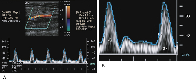
The word spectrum, as derived from Latin, means image. You may think of the Doppler spectrum as an image of the Doppler frequencies generated by moving blood.1–8 In fact, this image is a graph showing the mixture of Doppler frequencies present in a specified sample of a vessel over a short period of time.1–3 The key elements of the Doppler spectrum are time, frequency, velocity, and Doppler signal power. These elements are best described in pictorial form; therefore, this information is provided in Figure 3-1, rather than in the text. Please review this figure now, directing particular attention to the four key elements cited previously.
The Power Spectrum
The Doppler frequency spectrum that you have just reviewed in Figure 3-1 is sometimes called a power spectrum,1–3 because the power, or strength, of each frequency is shown by the brightness of the pixels. The power of a given frequency shift, in turn, is proportionate to the number of red blood cells producing that frequency shift. If a large number of blood cells are moving at a certain velocity, the corresponding Doppler frequency shift is powerful, and the pixels assigned to that frequency are bright. Conversely, if only a small number of cells are causing a certain frequency shift, the pixels assigned to that frequency are dim. The power spectrum concept is important for understanding power Doppler flow imaging, which is discussed later in this chapter. The concept of the power Doppler spectrum is nicely illustrated in Figure 2-29.
Frequency Versus Velocity
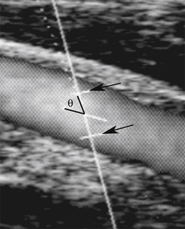
The echoes that are reflected back to the transducer from moving cells in a sampled blood vessel contain only Doppler frequency shift information; yet the Doppler spectrum often displays both velocity (cm/sec or m/sec) and frequency (kHz) information. How does the instrument convert the Doppler frequency shift to velocity? This conversion occurs when the sonographer “informs” the duplex instrument of the Doppler angle,1,2,9 which is shown in Figure 3-2. If the instrument “knows” the Doppler angle, it can then compute the blood flow velocity via the Doppler formula (see Chapter 2). You may note in this formula that the frequency shift is proportional to the cosine of the Doppler angle, theta. When the operator informs the ultrasound machine of this angle, the frequency shift is proportional to blood flow velocity. Voila! The frequency spectrum becomes a velocity spectrum. A Doppler angle of 60 degrees or less is required to derive accurate frequency and velocity measurements. If the angle is greater than 60°, velocity measurements are unreliable. Although there is greater error in measurements obtained at higher angles, some applications (e.g., carotid examinations) are more easily performed at angles closer to 60°. It is generally recommended that the Doppler angle should be less than or equal to, but not greater than 60° for greatest accuracy.
In spite of potential measurement inaccuracy described in the previous paragraphs, it is desirable to operate the duplex instrument in the velocity mode rather than the frequency mode for two reasons.1,2,9 First, velocity measurements compensate for variations in vessel alignment relative to the skin surface. For instance, the Doppler frequency shift observed in a tortuous internal carotid artery might be radically different from one point to another, but angle-corrected velocity measurements will be similar throughout the vessel, in spite of dramatic changes in vessel orientation relative to the skin. Second, the Doppler frequency shift is inherently linked to the output frequency of the transducer, but velocity measurement is independent of the transducer frequency. For instance, if the output frequency goes from 5 to 10 MHz, the frequency shift is doubled. Imagine the clinical consequences of such frequency changes. If transducers with different frequencies were used to determine stenosis severity, different diagnostic parameters would be needed for each ultrasound transducer (e.g., 3.5, 5, or 7.5 MHz). This problem is eliminated when the instrument converts the “raw” frequency information to velocity data.
Auditory Spectrum Analysis
The Sample Volume
The frequency spectrum shows blood flow information from a specific location called the Doppler sample volume, which is illustrated in Figure 3-2. You should be familiar with the following three characteristics of the Doppler sample volume: First, it is, in fact, a volume (three dimensions), even though only two of its dimensions are shown on the duplex image. The “thickness” of the sample volume cannot be shown on the two-dimensional spectrum display, and this can sometimes lead to errors of localization. Doppler signals may be obtained from vessels that are marginally within the sample volume but are not shown on the two-dimensional display. For instance, the ultrasound image may show the internal carotid artery, but you may actually be receiving flow signals from an adjacent external carotid branch. Second, the actual shape and size of the sample volume may be somewhat different from the linear representation shown on the duplex image. Third, and most important, the Doppler spectrum displays flow information only within the sample volume and does not provide information about flow in other portions of the blood vessel that are visible on the ultrasound image. Therefore, if the sample volume is positioned incorrectly, key diagnostic information may be overlooked.
Waveforms and Pulsatility
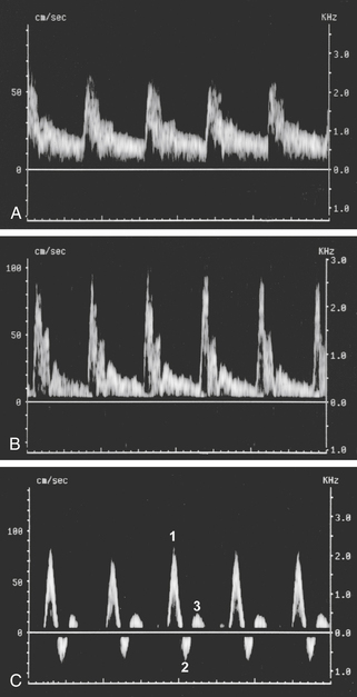
In arteries, each cycle of cardiac activity produces a distinct “wave” on the Doppler frequency spectrum that begins with systole and terminates at the end of diastole. The term waveform refers to the shape of each of these waves, and this shape, in turn, defines a very important flow property called pulsatility.1,2,10–28 In general terms, Doppler waveforms have low, moderate, or high pulsatility features, as illustrated in Figure 3-3. Please review this figure before proceeding to the material that follows.
Low-pulsatility Doppler waveforms have broad systolic peaks and forward flow throughout diastole (see Figure 3-3, A). The carotid, vertebral, renal, and celiac arteries all have low-pulsatility waveforms in normal individuals because these vessels feed circulatory systems with low resistance to flow (low peripheral resistance). Low-pulsatility waveforms are also monophasic, meaning that flow is always forward, and the entire waveform is either above or below the Doppler spectrum baseline (depending on the orientation of the ultrasound transducer).
Moderate-pulsatility Doppler waveforms have an appearance somewhere between the low- and high-resistance patterns (see Figure 3-3, B). With moderate flow resistance, the systolic peak is tall and sharp, but forward flow is present throughout diastole (perhaps interrupted by early-diastolic flow reversal). Examples of moderate pulsatility are found in the external carotid artery and the superior mesenteric artery (during fasting).
High-pulsatility Doppler waveforms have tall, narrow, sharp systolic peaks and reversed or absent diastolic flow. The classic example of high pulsatility is the triphasic flow pattern seen in an extremity artery of a resting individual (see Figure 3-3, C). A sharp systolic peak (first phase) is followed by brief flow reversal (second phase) and then by brief forward flow (third phase). High-pulsatility waveforms are a feature of circulatory systems with high resistance to blood flow (high peripheral resistance).
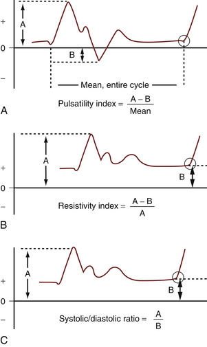
Pulsatility and flow resistance may be gauged qualitatively, either by visual inspection of the Doppler spectrum waveforms or by listening to the auditory output of a Doppler instrument. Qualitative assessment of pulsatility is often sufficient for clinical vascular diagnosis, but in some situations (e.g., assessment of renal transplant rejection), quantitative assessment is desirable. A variety of mathematical formulae can be used for this purpose, but the most popular measurements are the pulsatility index (of Gosling), the resistivity index (of Pourcelot), and the systolic/diastolic ratio,24,26,28,29 all of which are illustrated in Figure 3-4.
Acceleration
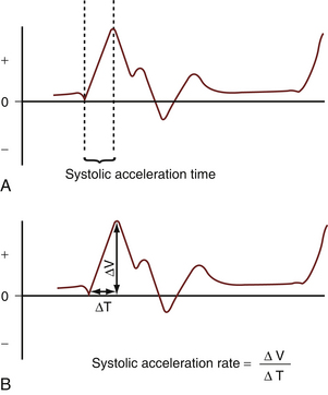
Acceleration is another important flow feature evident in Doppler spectral waveforms.24,25 In most normal situations, flow velocity in an artery accelerates very rapidly in systole, and the peak velocity is reached within a few hundredths of a second after ventricular contraction begins. Rapid flow acceleration produces an almost vertical deflection of the Doppler waveform at the start of systole (Figure 3-5, A). If, however, severe arterial obstruction is present proximal (upstream) to the point of Doppler examination, systolic flow acceleration may be slowed substantially, as shown in Figure 3-5, B and C. Quantitative measurement of acceleration is achieved by measuring the acceleration time and the acceleration rate (index), as illustrated in Figure 3-6. These measurements are used, for example, in evaluating renal artery stenosis.
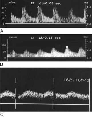
FIGURE 3-5 Acceleration and damping. A, The acceleration time (0.03 sec) is normal in the right kidney. B, The acceleration time is prolonged (0.15 sec) in the left kidney due to severe proximal renal artery stenosis. (A and B are from the same patient.) C, Severely damped dorsalis pedis artery waveform distal to common iliac and superficial femoral artery occlusion. Normally, this waveform should look like Figure 3-3, C. Acceleration is severely delayed, and a large amount of flow is present throughout diastole, consistent with severe ischemia.
Vessel Identity
As you may have already surmised, vessels can be identified by their waveform pulsatility features.1,2,14,21–23,26 For example, Doppler waveforms readily differentiate between lower extremity arteries, which are distinctly pulsatile, and veins, which have gently undulant flow features. Doppler waveforms are particularly helpful in distinguishing the internal and external carotid arteries, which have low and moderate pulsatility, respectively. Pulsatility is also of value within the liver for differentiating among the portal veins, hepatic veins, and hepatic arteries, as discussed in Chapter 30.
Laminar and Disturbed Flow
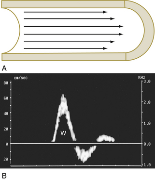
Blood generally flows through arteries in an orderly way, with blood in the center of the vessel moving faster than the blood at the periphery. This flow pattern is described as laminar, because the movement of blood is in parallel lines.1,2,4,14,15 When flow is laminar, the great majority of blood cells are moving at a uniform speed, and the Doppler spectrum shows a thin line that outlines a clear space called the spectral window (Figure 3-7).*
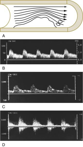
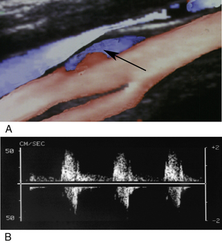
In disturbed flow, the movement of blood cells is less uniform and orderly than in laminar flow. Disturbed flow is manifested as spectral broadening or filling in of the spectral window.1,2,4,15–19 The degree of spectral broadening is proportionate to the severity of the flow disturbance, as illustrated in Figure 3-8. Although disturbed blood flow often indicates vascular disease, it must be recognized that flow disturbances also occur in normal vessels. Kinks, curves, and arterial branching may produce flow disturbances, as illustrated quite vividly in the carotid bulb, where a prominent area of reversed flow is a normal occurrence11,20,21 (Figure 3-9). In addition, a spurious disturbed flow appearance may be created in normal arteries through the use of a large sample volume that encompasses both the slow-flow area near the vessel wall and more rapid flow at the vessel center.16–19 The Doppler spectrum, in such cases, appears broadened because both the high-velocity flow at the vessel center and the slow flow at the periphery of the vessel are encompassed by the wide sample volume.
Volume Flow
Modern duplex instruments are capable of measuring the volume of blood flowing through a vessel (volume flow).1,2,30–32 This is done by measuring the average flow velocity across the entire lumen (slow peripheral flow and high central flow) through several cardiac cycles while simultaneously measuring the vessel diameter, which is converted mathematically into cross-sectional area. Knowing the average velocity and the vessel area, it is an easy matter for the Doppler instrument to calculate the blood flow (in mL/min), and this is done automatically by the ultrasound instrument. Although the ability to calculate volume flow has been available on duplex instruments for more than 20 years and measurement accuracy appears satisfactory, issues of reproducibility have kept volume flow measurements from routine use in a clinical setting.†
Diagnosis of Arterial Obstruction
Now that we have covered the basic concepts of Doppler spectral analysis, we can turn to the “heart of the matter,” namely, how to use Doppler spectral analysis to diagnose arterial obstruction. Five main categories of information are used in this process: (1) increased stenotic zone velocity, (2) disturbed flow in the poststenotic zone, (3) proximal pulsatility changes, (4) distal pulsatility changes, and (5) indirect effects of obstruction, such as collateralization.‡ These categories are summarized in Table 3-1, and each is discussed in the following sections.
TABLE 3-1 Spectral Features of Arterial Obstruction
| Local effects |
| Elevated flow velocity in the stenotic lumen |
| Poststenotic flow disturbance |
| Proximal (upstream) pulsatility changes |
| Increased pulsatility |
| Decreased velocity overall, due to decreased flow |
| Distal (downstream) pulsatility changes |
| Slowed systolic acceleration |
| Broad systolic peak |
| Increased diastolic flow (reduced peripheral resistance) |
| Decreased velocity overall |
| Secondary (collateral) effects |
| Increased size, velocity, and volume flow in collateral vessels |
| Reversed flow in collateral vessels |
| Decreased pulsatility (flow resistance) in collateral vessels |
Increased Stenotic Zone Velocity
The term stenotic zone refers to the narrowed portion of the arterial lumen. For determining the severity of arterial stenosis, the single most valuable Doppler finding is increased velocity in the stenotic zone. Flow velocity is increased in the stenotic zone because blood must move more quickly if the same volume is to flow through the narrowed lumen as through the larger, normal lumen. The increase in stenotic zone velocity is directly proportional to the severity of luminal narrowing.
Three stenotic zone velocity measurements are commonly used to determine the severity of arterial stenoses (Figure 3-10): (1) peak systolic velocity
Stay updated, free articles. Join our Telegram channel

Full access? Get Clinical Tree


