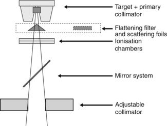
Figure 3.8. In this location, although the chamber is protected as far as practicable from backscatter that arises from the adjustable collimator jaws, it will still be subject to some backscatter. The monitor chamber may also be subject to backscatter from any physical wedges placed in the beam. Variations in backscatter contribute to changes in output with field size and to the apparent effect of the wedge. In kV therapy units, the monitor chamber is located after the exit window of the tube housing and after any added beam filters, so that it samples the final beam. However, the monitor chamber is susceptible to backscatter from the applicator plate and this contributes to differences in output between different treatment applicators.

Figure 3.8 Schematic diagram of a linear accelerator treatment head showing the location of the monitor (ionization) chambers in relation to other components of the head.
Stay updated, free articles. Join our Telegram channel

Full access? Get Clinical Tree


